


Brief introduction about VLAN topology in Omada Network v6


Contents
Getting device information and customizing your topology
Filtering and highlighting devices in the network topology
Additional view about network topology in LAN
Introduction
This FAQ introduces some tips and highlights about VLAN topology in Omada Network v6.
Requirements
- Omada controller v6
Configuration
Getting device information and customizing your topology
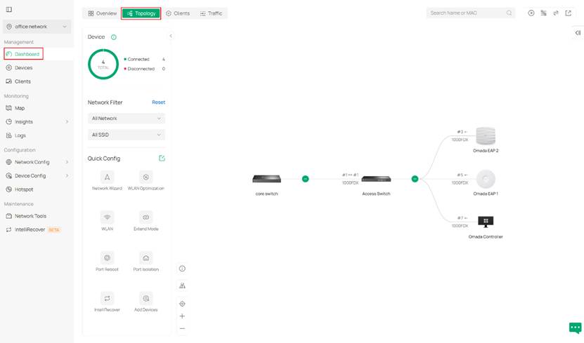
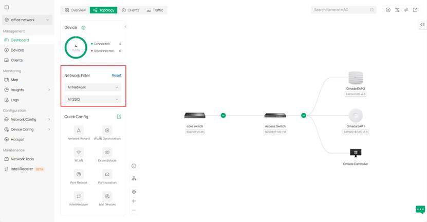
Step 1. First, we enter the topology map in Omada Controller. With the latest v6, it lies under the Dashboard > Topology, as shown below.
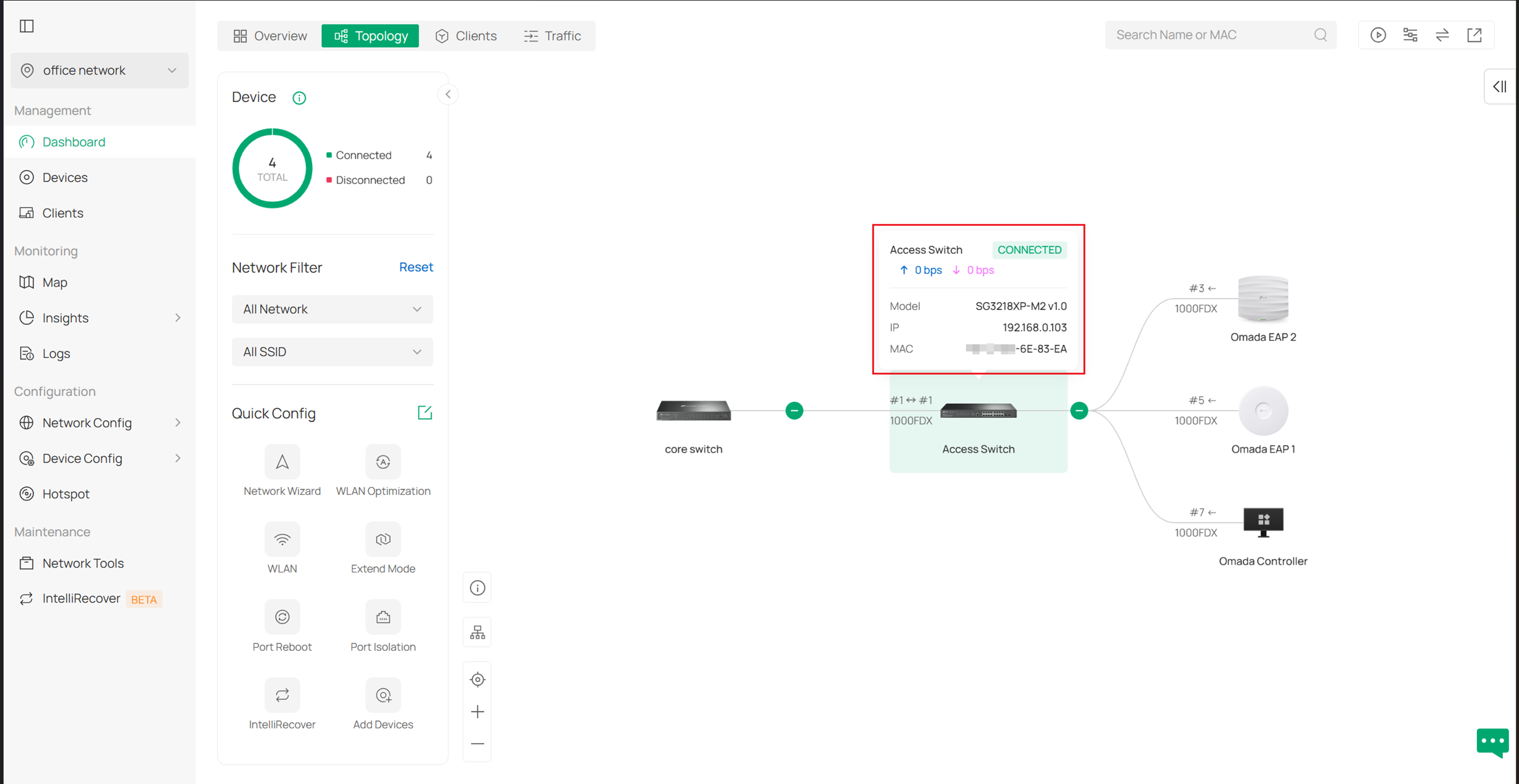
Step 2. When hovering your mouse on a specific device, you can see some of its relevant information including traffic, model type, IP address and Mac address.
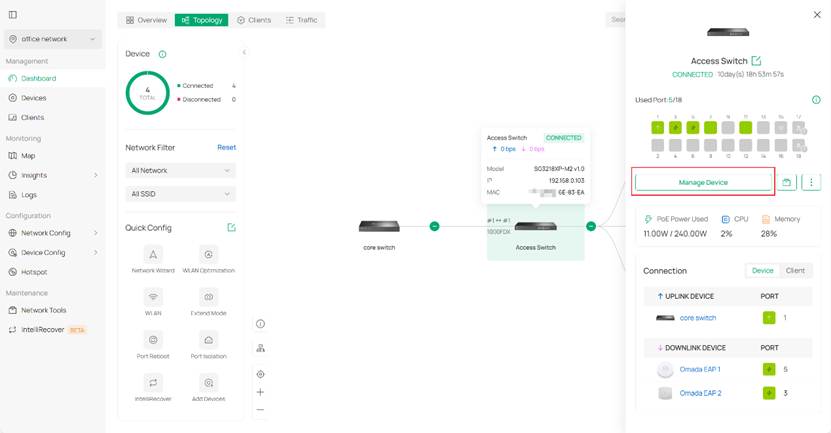
Step 3. If these are not enough for you, you may click the device to open its detailed drawer page for more information, just like in previous versions. If that still doesn't feed your need, click Manage Device to get a full page of device configuration.
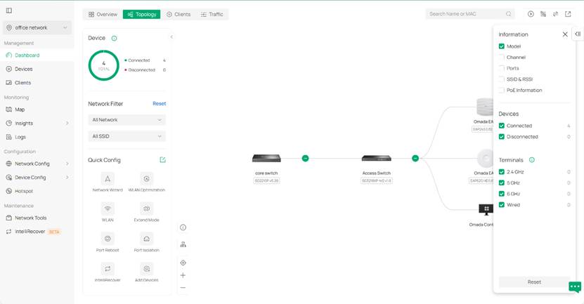
Step 4. You can also customize the information shown on the topology view by using the tools on the top right. You can show traffic, set filters and change root node of the topology by using these tools.
E.g. I don’t want to see ports but device model on the topology view, thus I come to the filter on the top right and tickle the model and remove ports.
Filtering and highlighting devices in the network topology
Step 1. We have a network filter for quickly reviewing and checking if the network is set as expected. It’s on the left side of the topology page.
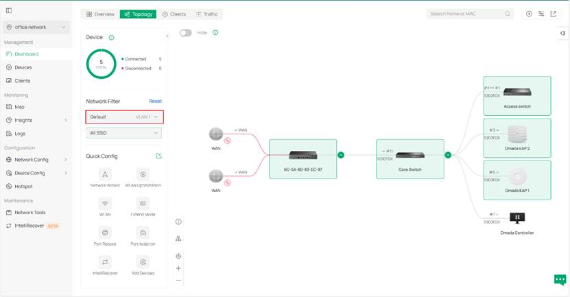
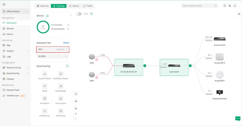
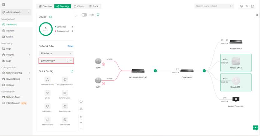
Step 2. We use the network filter to get a specific topology view about a specific VLAN. Here are displays demonstrating VLAN networks.
The device will be highlighted if any of the following conditions are met:
For gateways
- The gateway functions as a DHCP server.
- There exists a LAN port whose PVID matches the current VLAN.
- There exists a downstream port with status up, and the current VLAN is among the VLANs configured on that port.
- For wireless routers, the wireless component follows the highlighting rules applied to APs.
For switches
- The switch functions as a DHCP server or relay.
- There exists a port whose PVID matches the current VLAN.
- There exists a downstream port with status up, and the current VLAN is included in its tagged or untagged VLAN list.
- The switch is configured with OUI-based VLAN.
For access points
- There exists a port whose PVID matches the current VLAN.
- (For EAPs possessing downstream ports) There exists a downstream port with status up, and the current VLAN is included in its tagged or untagged VLAN list.
- There is an SSID whose VLAN includes the current VLAN (SSID override VLAN configuration takes precedence). If the SSID is set to default, it is considered associated with the default VLAN.
- The encryption type is PPSK without RADIUS, and the VLAN configured in the corresponding profile’s PSK matches the current VLAN. (The number of PPSK entries is limited based on the device’s supported capacity.) If the PSK has no VLAN value, it is considered associated with the default VLAN.
For OLTs
- The S-VLAN includes the current VLAN.
When using filters for SSIDs, devices will be highlighted if the APs or wireless gateways are broadcasting this SSID.
When filtering by both VLAN and SSID simultaneously, the highlighted devices are the intersection of those highlighted when each filter is applied individually.
Additional view about network topology in LAN
Be aware that this section applies to Omada controller v6.2 or above.
In Dashboard > Topology (or Network Config > LAN topology preview), you will see your network topology based on different VLANs. In this topology map, you can have a view of link connections regarding the selected VLAN.
Generally, the solid line on this map refers to wired connections and the dashed lines indicate wireless connections. The link color reflects whether traffic for the selected VLAN can be transmitted over that link. 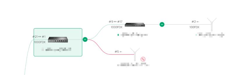
For device-to-device links
A green link means that traffic for the target VLAN can be transmitted normally over the link in both directions. It requires that ports on both ends of the link support the target VLAN, and the upstream device is highlighted. E.g. the link between two switches in picture above.
A red link means that traffic for the target VLAN cannot be transmitted over the link. This happens when ports of either ends do not support the target VLAN (or when disconnection happens) and at least one of the two devices is highlighted for that VLAN. Or, when both ends support the target VLAN, but upstream device is not highlighted. E.g. the link between highlighted switch and EAP in picture above.
A gray link means that neither of the two connected devices is highlighted for that VLAN (i.e. the selected VLAN is not involved in transmission over that link). E.g. the link between non-highlighted switch and EAP in picture above.
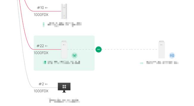
For device-to-client links
Green solid line: The wired client is using the target VLAN, and the port supports it
Gray solid line: The wired client is not using the target VLAN, or the port does not support it
Green dashed line
The client is connected to an SSID associated with the target VLAN, and is using that VLAN (PPSK)
Gray dashed line
The client is connected to an SSID associated with the selected VLAN, but is not actually using that VLAN (PPSK). Or the client is connected to an SSID not associated with the target VLAN
Conclusion
Briefly summarize the configuration results in one or two sentences.
Get to know more details of each function and configuration please go to Download Center to download the manual of your product.
