


How to Configure SD-WAN via Omada Controller v6.2


Contents
NAT Rule Configuration for Gateway Adoption (Optional)
Introduction
Software-Defined Wide Area Network (SD-WAN) revolutionizes traditional WAN architectures by leveraging centralized control and automation to dynamically route traffic across multiple connections (e.g., MPLS, broadband, LTE). SD-WAN enhances the hub-and-spoke model by integrating intelligent traffic steering and simplified cross-site management. Key benefit is centralized Policy Management, which defines and enforces network rules across all sites from a single Controller.
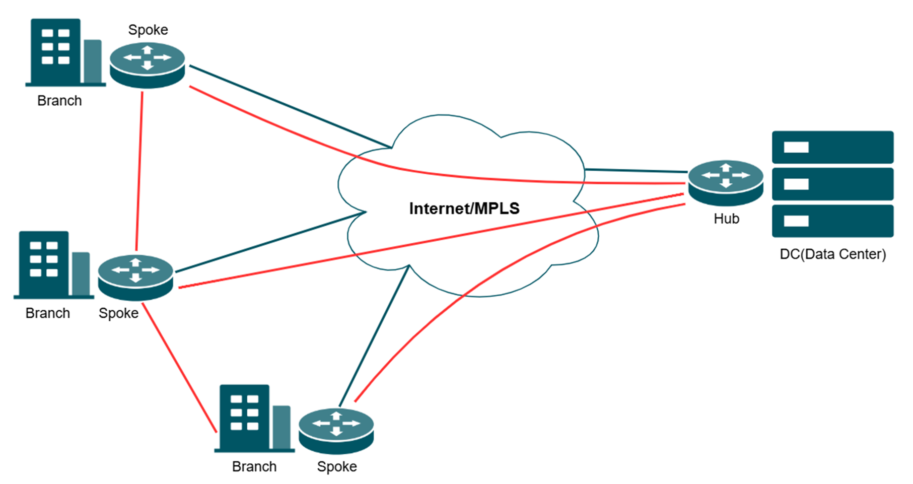
Note:
- The WAN participating in the networking cannot enable the DMZ function.
- All the spokes need to connect to the hub first.
This article provides a comprehensive walkthrough for configuring the SD-WAN function on the Omada Controller, enabling enterprises to centralize network management, optimize traffic routing, and establish secure hub-spoke connectivity across distributed sites in one Controller. The guide covers prerequisites, gateway adoption, IP range allocation, and post-configuration verification to ensure reliable WAN performance.
Requirements
- Omada Gateway with firmware fully adapted to Omada Controller V6.2 and above
- Omada Controller V6.2 and above
Configuration
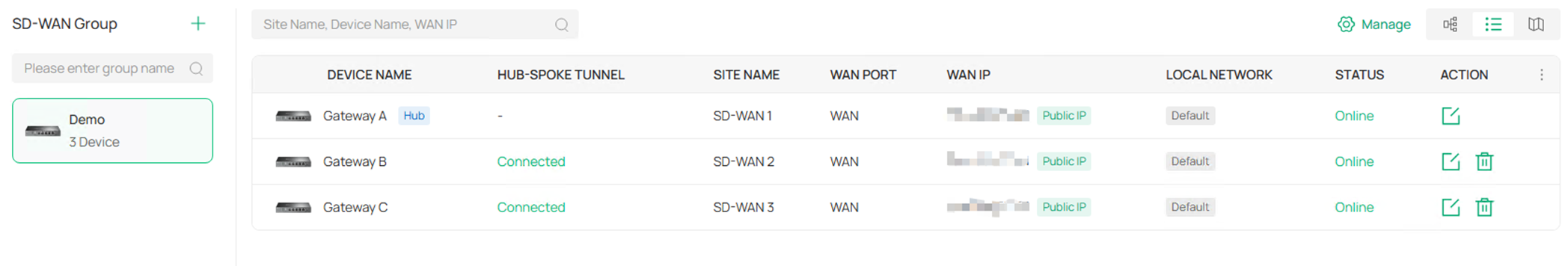
In the following section, we will introduce how to configure SD-WAN using three gateways as an example. The three gateways are adopted in three sites: SD-WAN 1/2/3 on the same controller and the gateways are named as Gateway A/B/C.
Please note that you must adopt the gateways with firmware supporting SD-WAN feature to be able to see the SD-WAN panel and continue all the following configurations!
NAT Rule Configuration for Gateway Adoption (Optional)
When using On-Premises controller, the gateways are usually adopted remotely, which requires the configuration of port forwarding to finish the adoption.
Step 1. The controller should be located at the LAN side of a gateway, after adopting this gateway, go to Network Config > NAT. 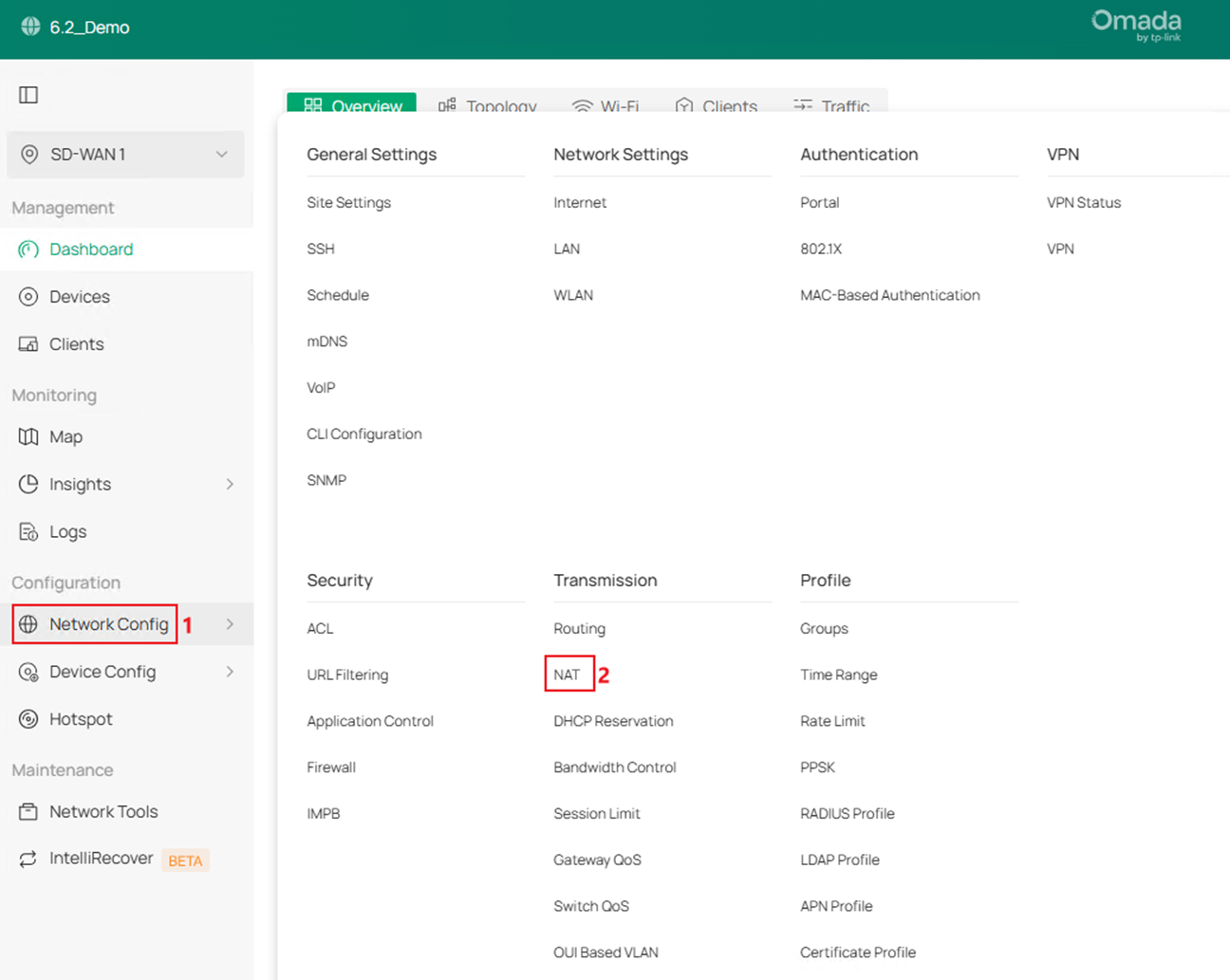
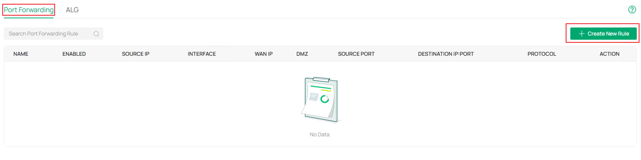
Step 2. In Port Forwarding page, click Create New Rule.
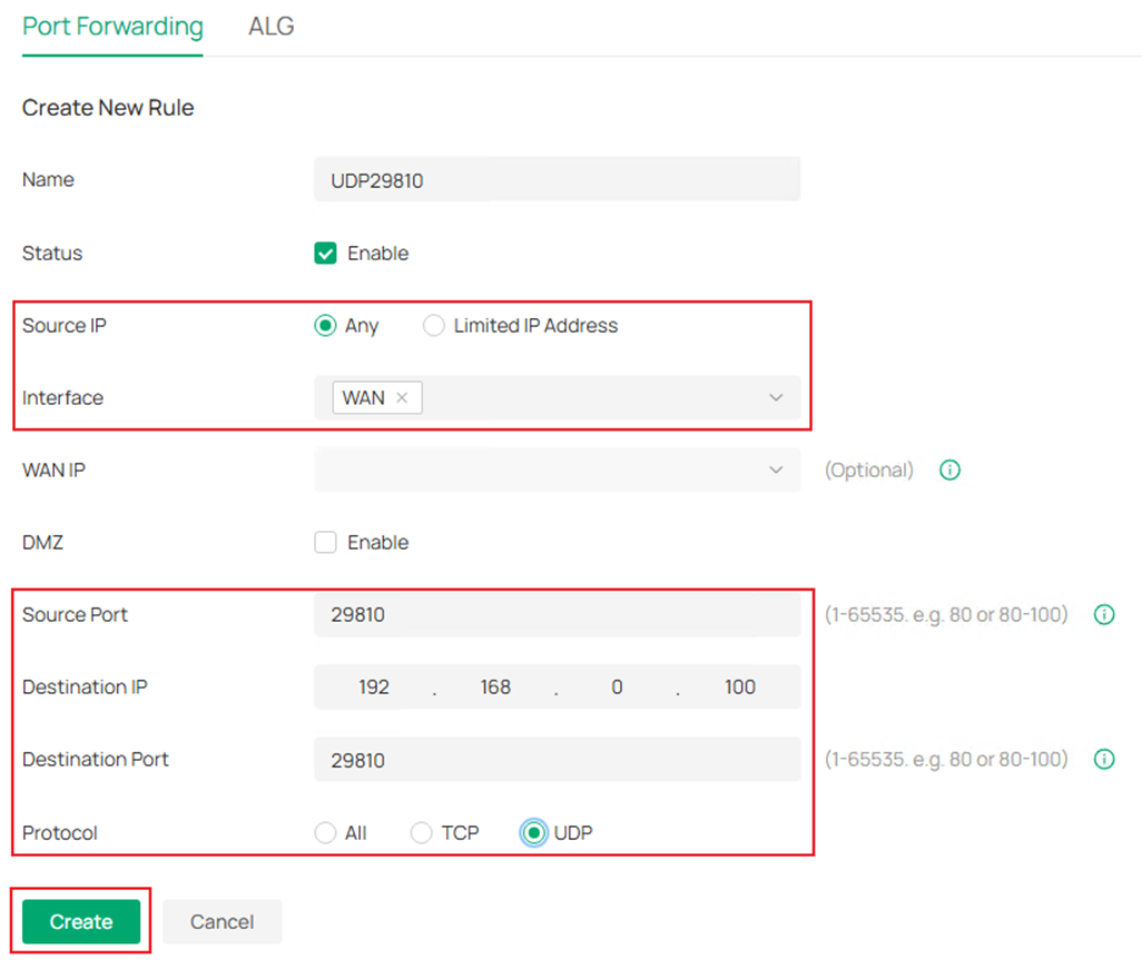
Step 3. Name the rule, choose to Any IP address or Limited IP Address able to use this port forwarding rule, then choose the correct WAN port as Interface. After that, configure the Source Port, Destination IP, Destination Port and Protocol. Finally, click Create.
For adopting an Omada device, the following ports need to be enabled: UDP29810, TCP29811-29817 and TCP8043. The following screenshot is an example of configuring port forwarding rule for UDP29810.
Step 4. After creating the port forwarding rule, configure the WAN IP address of this gateway as the Inform URL on other gateways to finish the adoption. Please note that the WAN IP address must be directly reachable from other gateways, otherwise you may need to configure more port forwarding rules in the uplink devices.
SD-WAN Configuration
If you have finished adopting all the gateways on the same controller, the SD-WAN configuration process starts here.
Step 1. Go to Global View > SD-WAN.
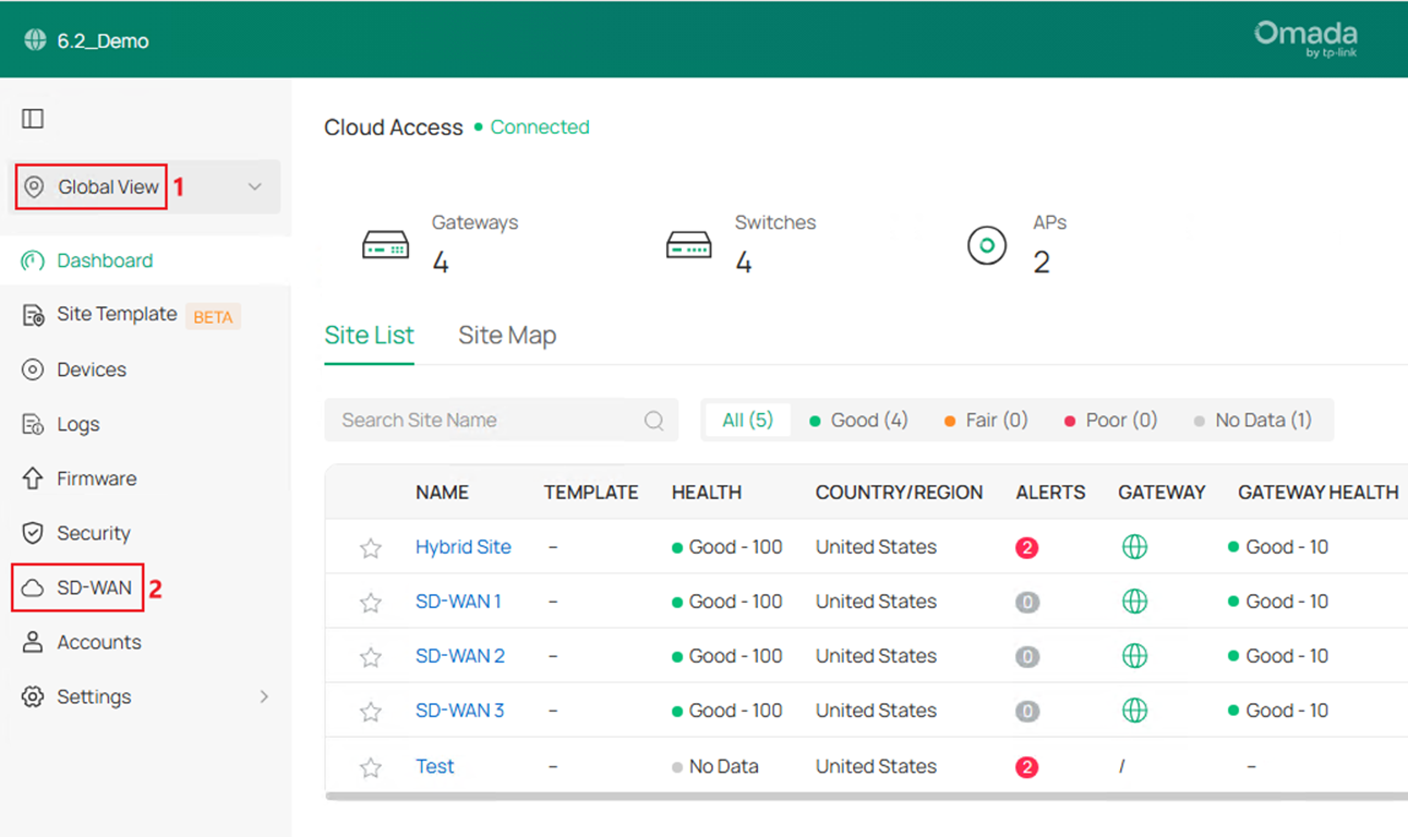
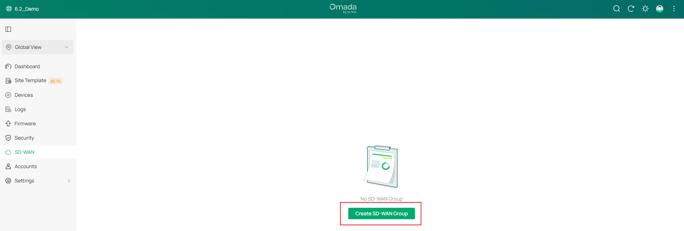
Step 2. Click Create SD-WAN Group.
Step 3. Edit the Group Name and Description if needed.
The Subnet Conflicts Solution is newly supported in Omada Controller V6.2, it maps the conflict network segments of SD-WAN gateways to a virtual segment to solve the problem that conflict network segments could not join the same SD-WAN group, this option is enabled by default.
Starting from Omada Controller V6.2, there’s no need to manually configure the virtual SD-WAN IP pool for the gateways in the SD-WAN group, it will be automatically generated and assigned.
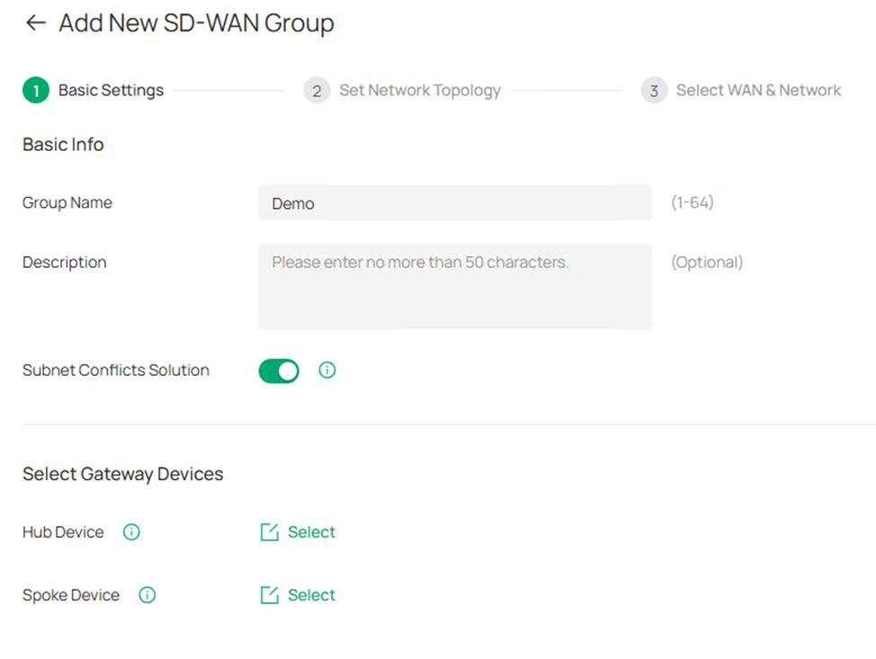
Step 4. Click the Select button to select Hub Device and Spoke Device. Please note that only the device with public IP address could act as Hub Device. Tick to select the device and click Save. 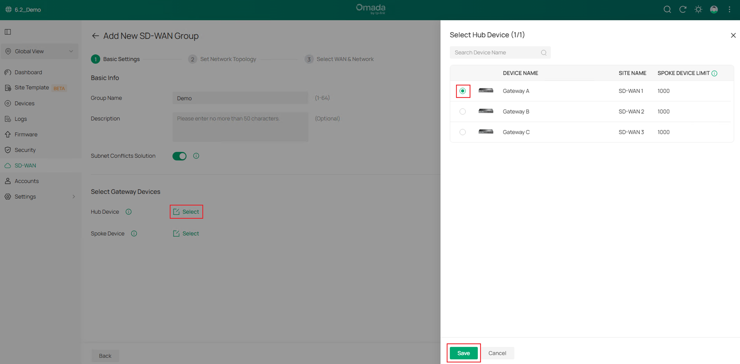
Step 5. After finished selecting the Hub and Spoke devices, click Next to proceed. 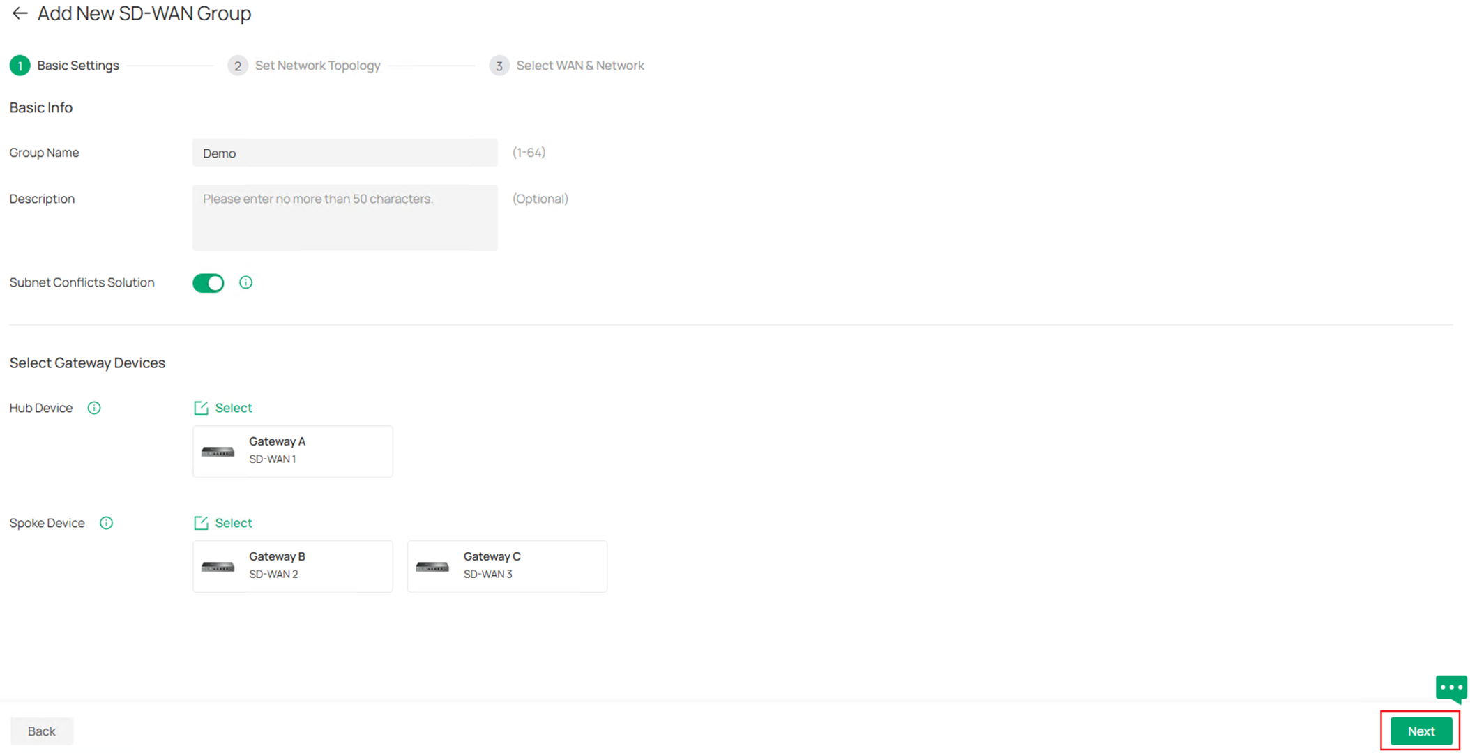
Step 6. In the Set Network Topology page, you could preview the tunnels created among the gateways. By default, only the Hub-Spoke tunnel will be created, all the traffic between spokes needs to be forwarded by the hub, you could also choose to establish the tunnels between spokes to connect them directly and reduce the pressure on the hub device, it could be configured by clicking Manage Spoke-Spoke Connection. Please note that to form a spoke-spoke connection, it’s required that at least one of the spokes have public IP address. 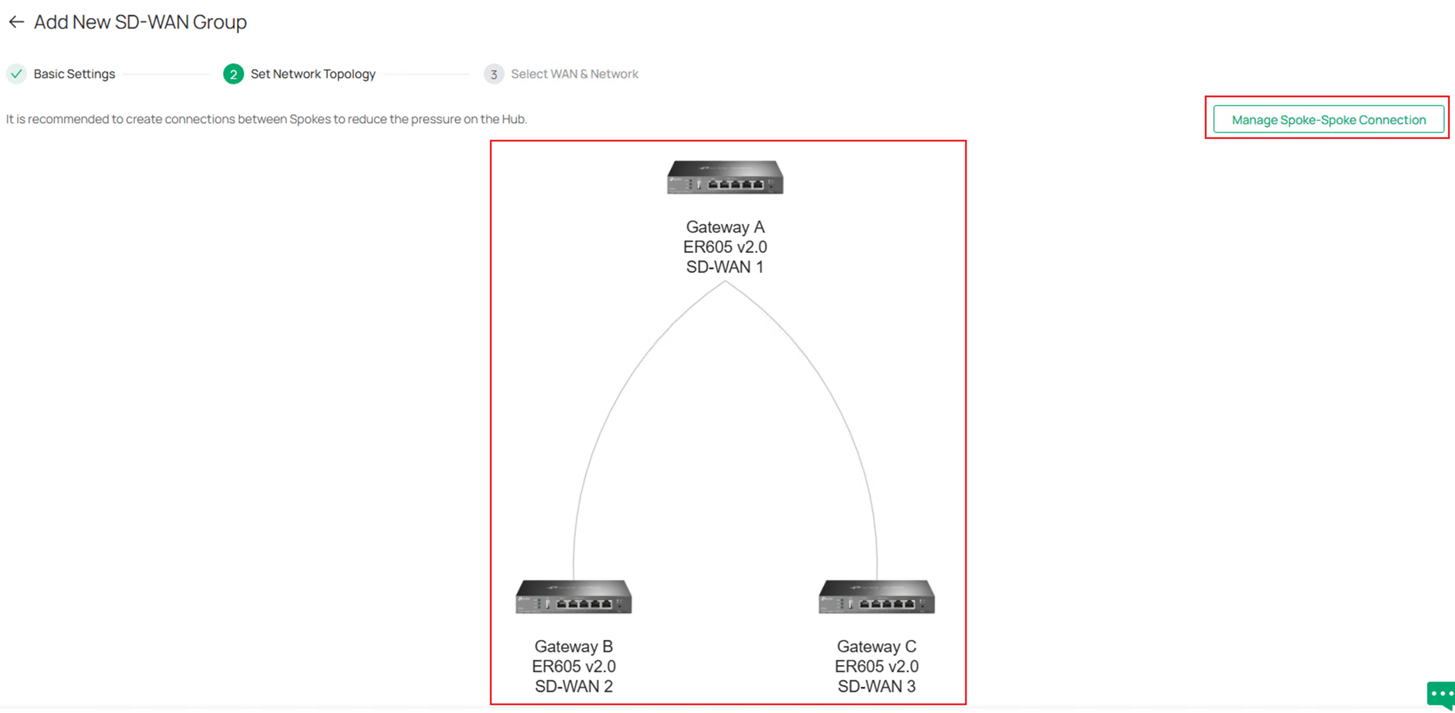
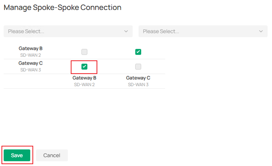
In Manage Spoke-Spoke Connection page, tick to select the connection and click Save.
After enabling spoke-spoke connection, the topology preview changes accordingly.
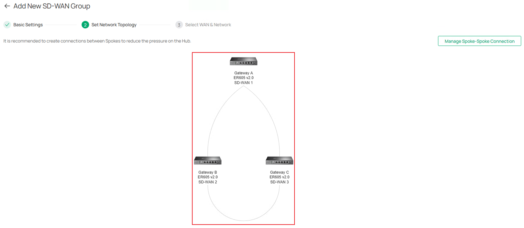
Click Next on the lower right to proceed.
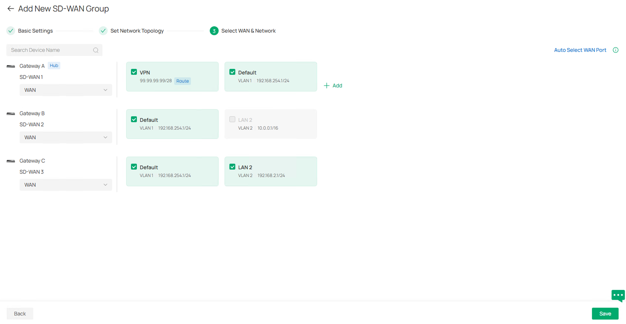
Step 7. In the Select WAN & Network page, click to select the WAN port participating in this SD-WAN group for each gateway, or click Auto Select WAN Port on the upper right, it will automatically choose the most suitable WAN, usually the ones with public IP.
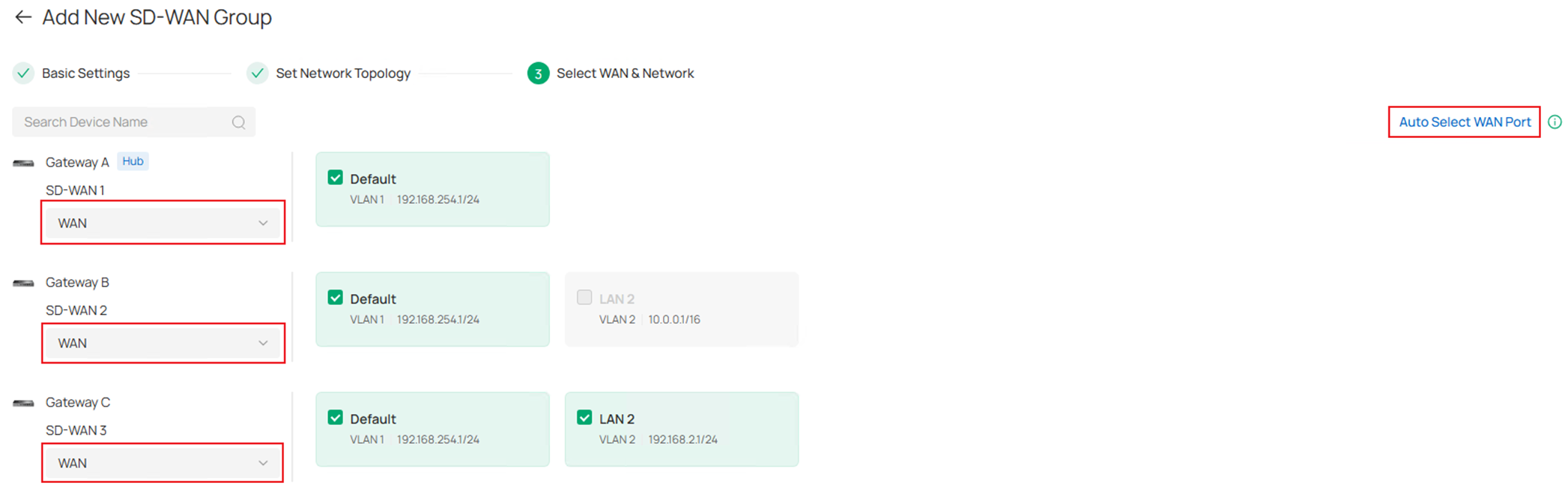
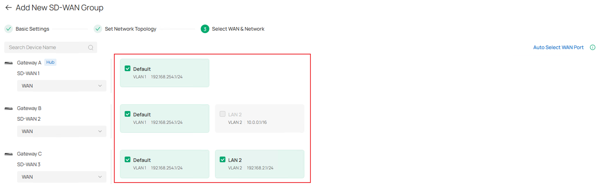
Click to choose the LAN networks on each gateway which you wish to participate in the SD-WAN group. Please note that only the LAN with subnet mask no lower than /20 could be selected, as an example, the LAN 2 on Gateway B has a mask of /16, it is grayed out and cannot be selected. Also, the overlapped subnets could be selected, it will then be mapped to a virtual subnet without conflict. Click Save on the lower right to continue.
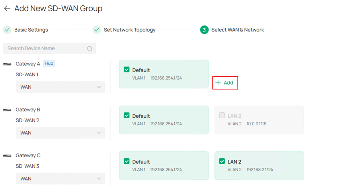
Step 8. (Optional). Starting from Omada Controller V6.2.10 and while using the Omada Gateway firmware adapted to Omada Controller V6.2, users are able to add a custom route into the SD-WAN group. This route is entered by user-self, not a subnet managed by Omada Controller. It may be a VPN tunnel, static subnet connected but not managed by Omada or some third party devices connected. This feature is only available on the Hub, click the Add button to add a Custom Route.
In the pop-up page, enter the name and destination subnet of this custom route. Click Save to finish creating.
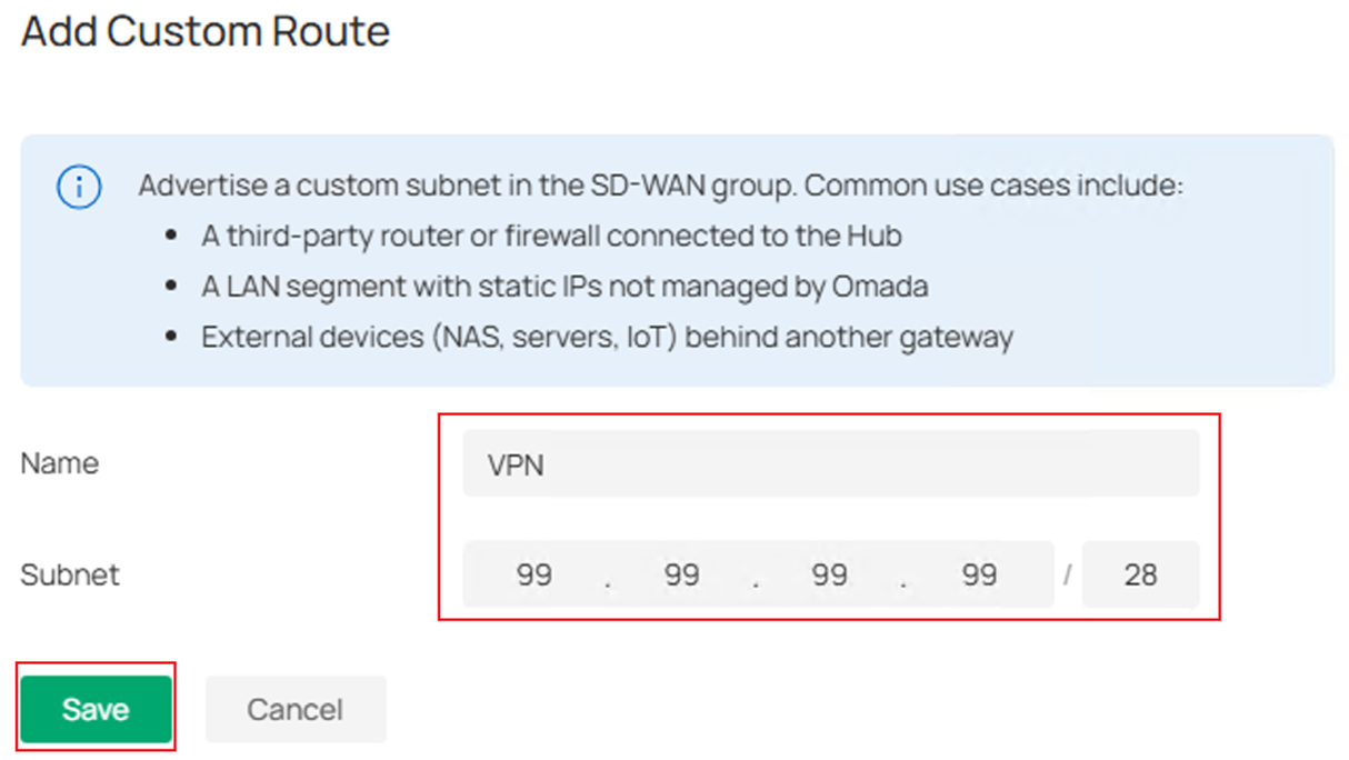
Please note that there must be a static route configured on the gateway which contains this Custom Route configured in SD-WAN to make it take effect. The static route for gateway could be configured in Network Config > Transmission > Routing, then go to Static Route tab.
After adding the custom route, LAN segment preview should look like the following screenshot, click Save to continue.
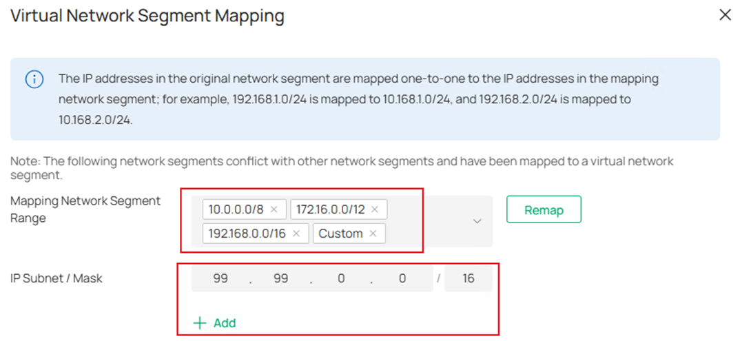
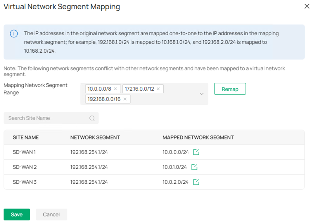
Step 9. As the overlapped subnets across gateways are selected and the Subnet Conflicts Solution is enabled, the Virtual Network Segment Mapping page will pop out to confirm the virtual mapping for overlapped subnets. By default, the virtual mapping range will be the private IP addresses, 10.0.0.0/8, 172.16.0.0/12 and 192.168.0.0/16, you could also choose to add Custom option and click Add to set the mapping range you want.
The mapping result will be generated automatically, if you would like to change, click the Edit button and change to the subnet you want. 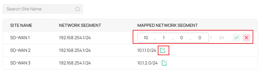
The subnet mask of the mapping subnet is same as the original subnet and could not be changed, this could ensure the original IP addresses within the range could be mapped one by one without conflict. For example, the subnet 192.168.254.1/24 is mapped to 10.1.0.0/24, the clients with IP 192.168.254.1 and 192.168.254.100 will be mapped to 10.1.0.1 and 10.1.0.100 accordingly.
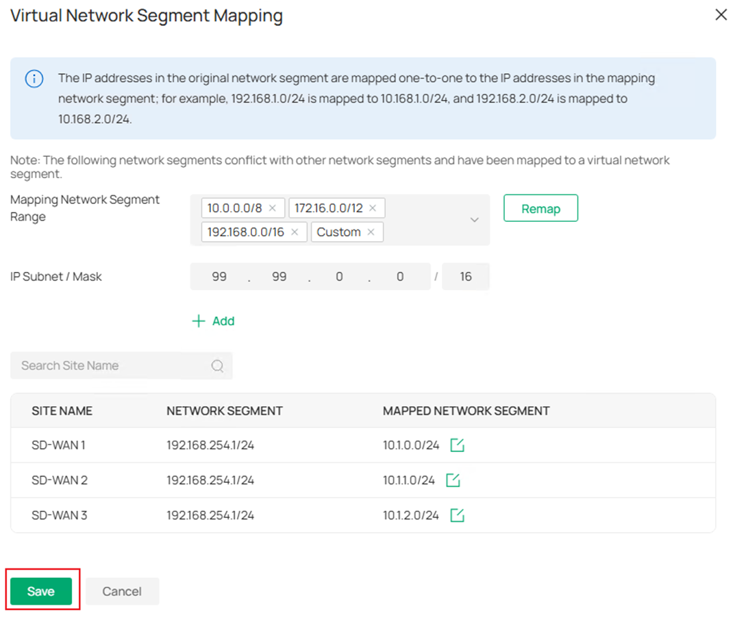
The sequence of Mapping Network Segment Range could be changed, as an example in the screenshot, the sequence is 10.0.0.0/8 > 172.16.0.0/12 > 192.168.0.0/16 > Custom. The first priority is 10.0.0.0/8, as a result, the virtual mapping segments generated are within this range, you could move any segment to the front to prioritize it as the generated virtual mapping range.
After confirming the virtual mapping configuration, click Save to proceed.
Step 10. After finish configuring the virtual mapping, the mapped subnets will be displayed under each subnet in the Select WAN & Network page. If there’s no problem, click Save to proceed. 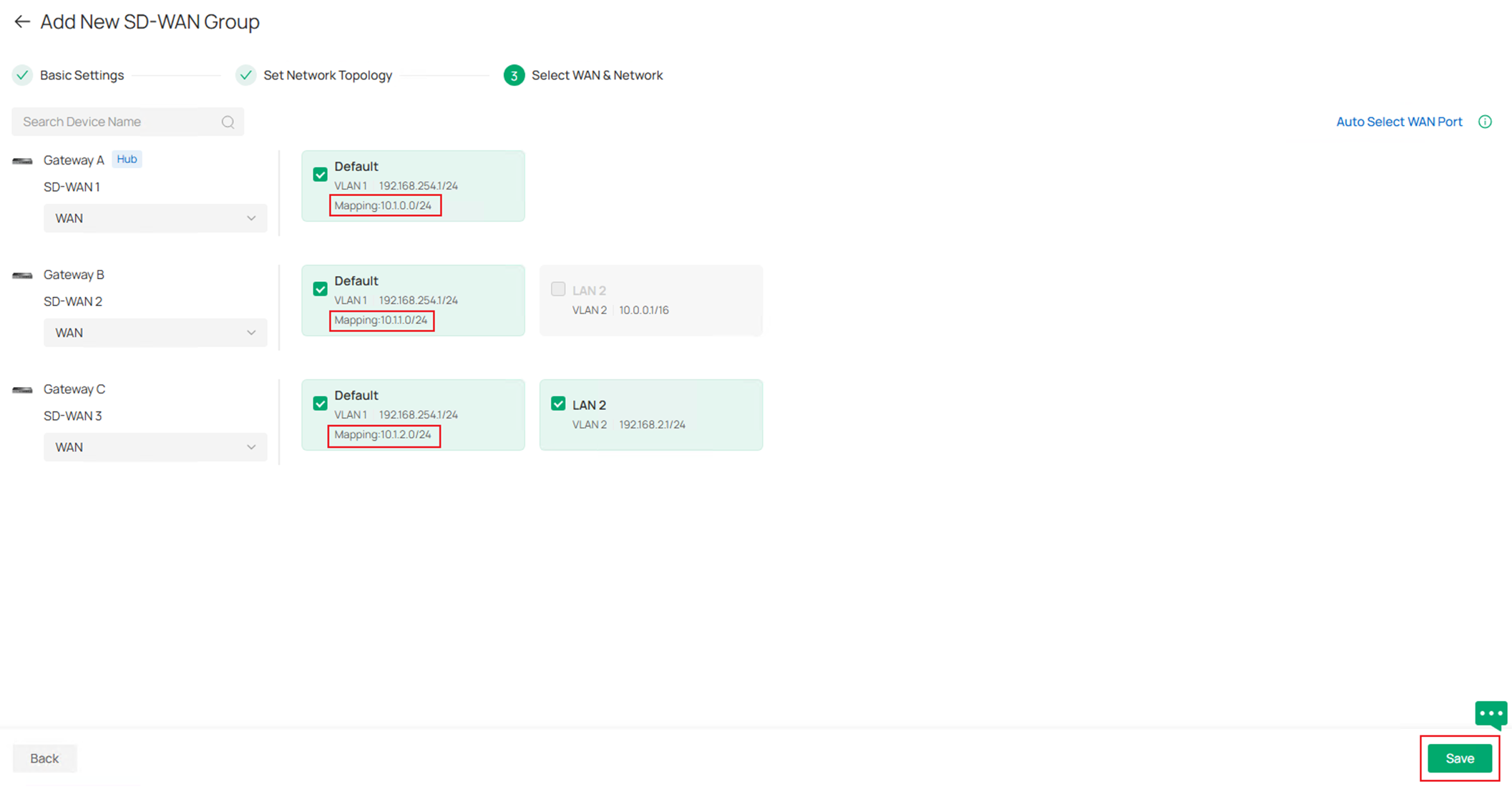
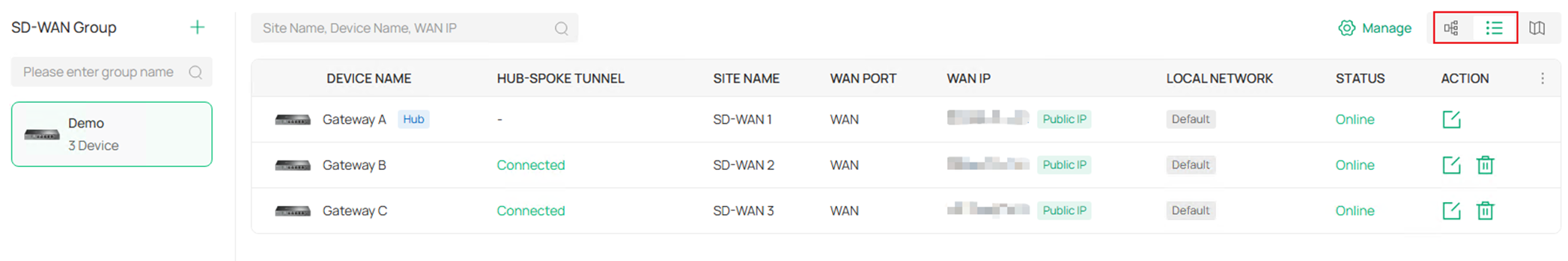
Step 11. The SD-WAN group configuration is finished, and you will return to the overall SD-WAN page, the status of SD-WAN group created will be displayed here. The two views could be changed by clicking the view button on the upper right.
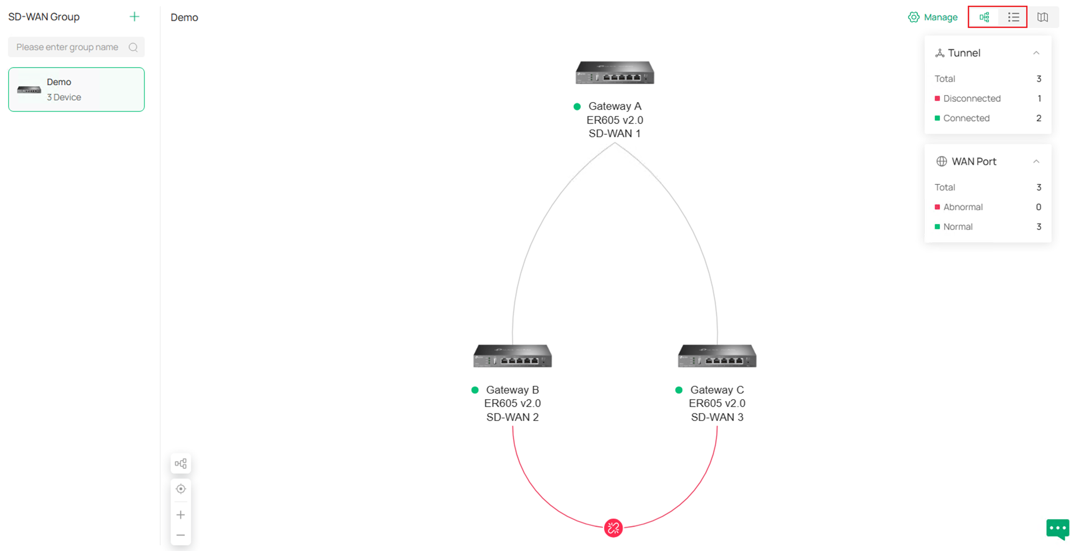
As shown in the example screenshot, the two Hub-Spoke tunnel is established but the Spoke-Spoke tunnel is not yet established.
Step 12. By clicking the Manage button on the upper right, you could choose to Edit Group, Delete Group or Manage Virtual Network.
By clicking Edit Group, you will go back to the SD-WAN group detailed configuration page.
By clicking Delete Group, the whole SD-WAN group will be deleted after confirmation.
By clicking Manage Virtual Network, you could check the status or edit the virtual mapping for overlapped network segments.
If you wish to change the network segment and mask of LAN participating in the SD-WAN group, it’s recommended to remove this LAN from SD-WAN group first, after finished changing the LAN settings, add it back to the SD-WAN group again, you also need to remap the conflict subnets afterwards.
Step 13. By clicking the Map button on the upper right, users are able to see the locations of sites on the map according to the longitude and latitude set for the site, or manually place it if there’s no longitude and latitude information. In the example screenshot, the longitude and latitude are not set, so the sites are unplaced and listed on the left panel, drag to manually place them on the map. 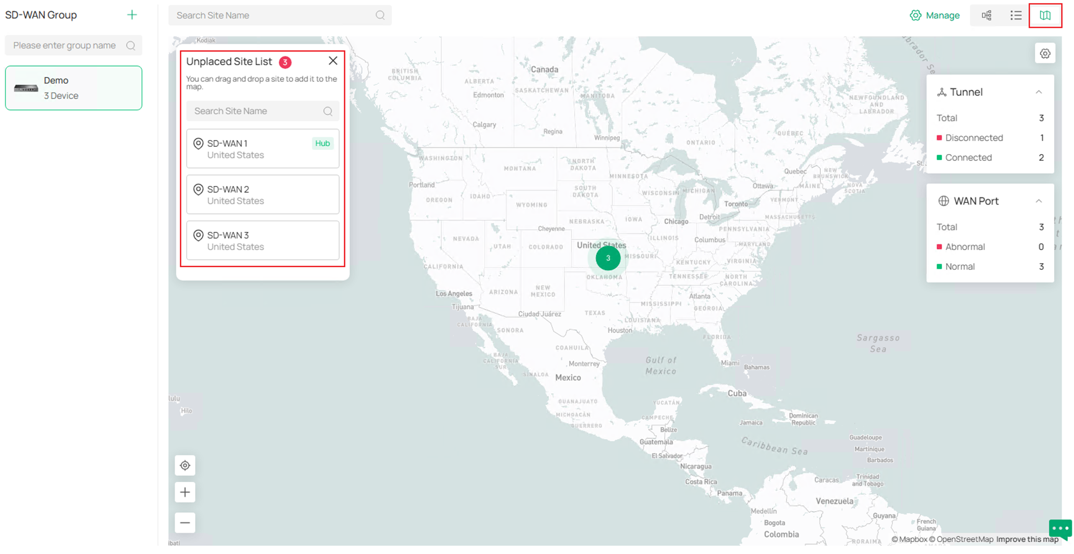
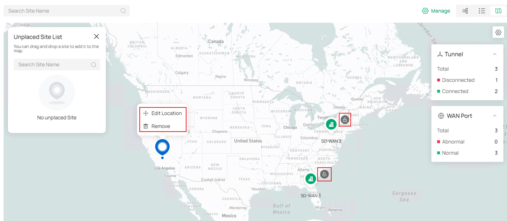
After placing the sites, click the Lock icon on each site icon to confirm the location, the tunnel status will then be visualized. Right click on the site icons to Edit Location or Remove.
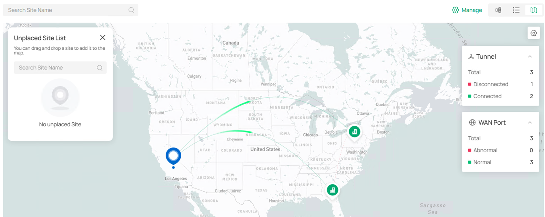
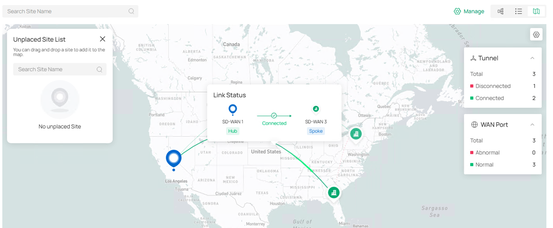
Move the cursor on the tunnels or site icons to check the status.
Verification
The SD-WAN group status could be checked in the SD-WAN page, including the gateways participated and tunnel status.
Go to one of the site and check the routing table of gateway, there will be route entries formed by SD-WAN.
Ping tools could also be used to verify the connectivity, please note that mapped virtual IPs need to be used for overlapped subnets.
Conclusion
In this article, we have introduced how to configure SD-WAN on Omada Controller V6.2 and above, there are some new features added for SD-WAN on this version.
Get to know more details of each function and configuration please go to Download Center to download the manual of your product.
QA
Q1:
What should I do if I downgrade devices in existed SD-WAN group with virtual NAT configured to the version not supporting virtual NAT?
A1: After the downgrade, the virtual NAT cannot take effect anymore, the original SD-WAN group will be removed and needs to be configured again manually.
Q2: How do I control which user is able to change or view the SD-WAN panel when logged in to Omada Controller?
A2: There are three types of privilege for SD-WAN panel when creating an account role: Modify, View Only and Block. If set as Block, this user will not see SD-WAN panel after logged in, if set as View Only, this user could see the SD-WAN panel but not able to make any change to current configuration, if set as Modify, this user has the full power of seeing and changing the configuration in SD-WAN panel. The role privilege could be configured at Global View > Accounts > Role, the privilege for default roles could not be changed, to customize, please click Add New Role to create your own one. Before Controller V6.2.10, the user with View Only or Modify privilege for SD-WAN panel could see the SD-WAN page and related sites even if this user doesn’t have access to these sites in Controller, which causes risk. Starting from Controller v6.2.10, only the user with access to all sites in controller, plus the corresponding privilege set for SD-WAN panel could see or modify SD-WAN panel.
