


Contents
Introduction
The alarm output function of an industrial-grade switch is one of the key features that ensure reliable operation in industrial automation and control environments. When an abnormal event occurs on the switch itself or within the connected industrial network, the device can output an alarm signal through a physical interface to notify maintenance personnel or trigger coordinated actions with other automation equipment. This alarm mechanism is typically implemented through passive relay contacts, ensuring stable and secure signal transmission.
The alarm trigger events supported by our IES switches include Power Interruption Alarm and Port Link Down Alarm.
Power Interruption Alarm: Triggered when the primary or redundant power supply of the switch experiences an abnormal condition or failure. Future updates will introduce additional power-related alarms, including overvoltage and undervoltage detection.
Port Link Down Alarm: Triggered when the link status of a specified port is detected as disconnected or abnormal.
Requirements
- Omada industrial switches
Configuration
Step 1. Access the management interface of the industrial switch, then enter the Alert section.
Step 2. Setting up alert configurations. The following statement describes the Power Interruption Alarm and the Port Link Down Alarm one by one.
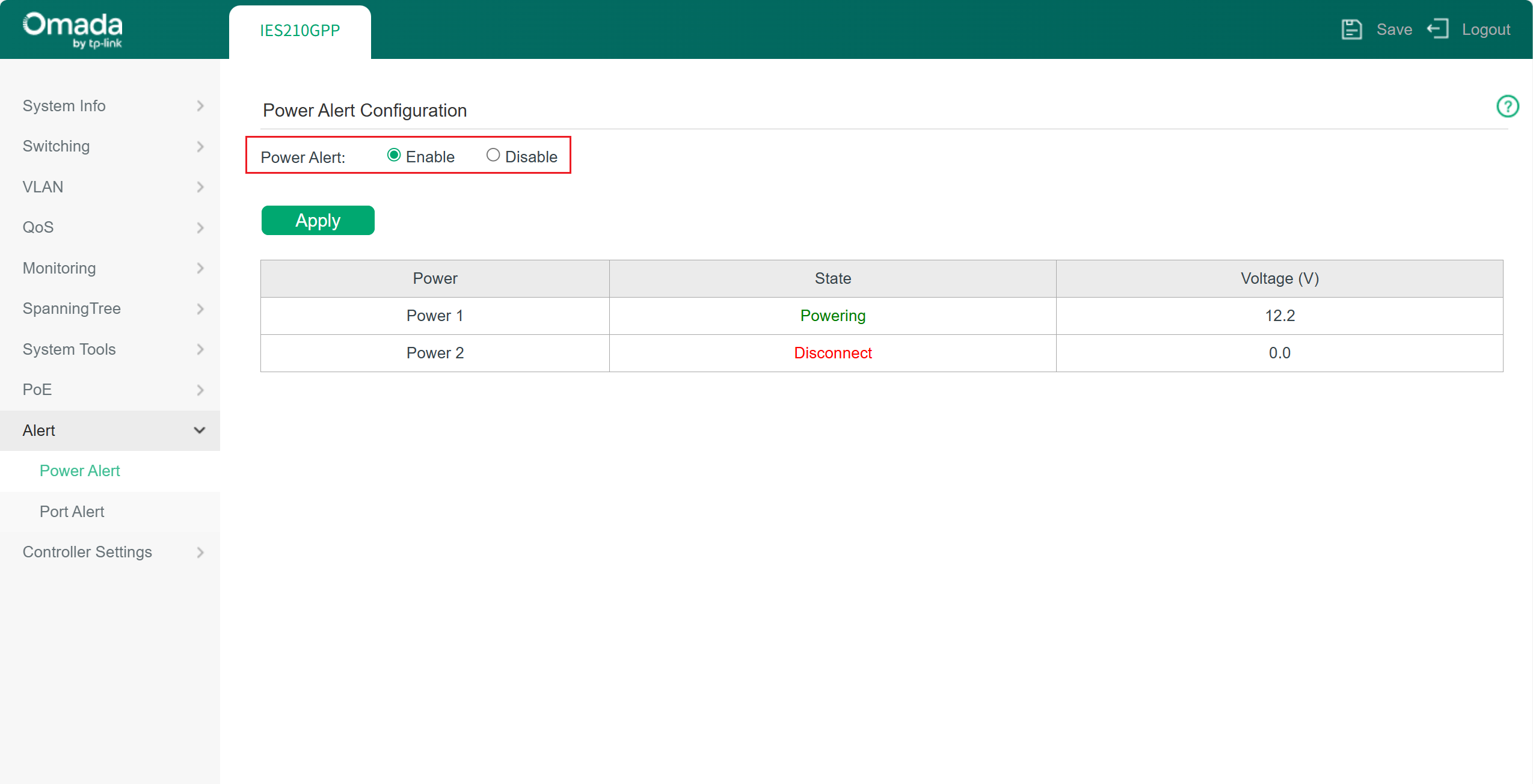
Power Interruption Alarm: it’s enabled by default. You may also check the current power status in this column. Powering means a normal power supply. The voltage has reached the startup threshold; Standby means power sources connected but not supplying power, voltage lower than threshold; Disconnect means no power sources.
Note: The switch with a single power supply will not have the alarm triggered even with Power Alert enabled. When the switch has a dual power supply, the power status will be monitored, and the alarm will be triggered if one or both power supply fail.
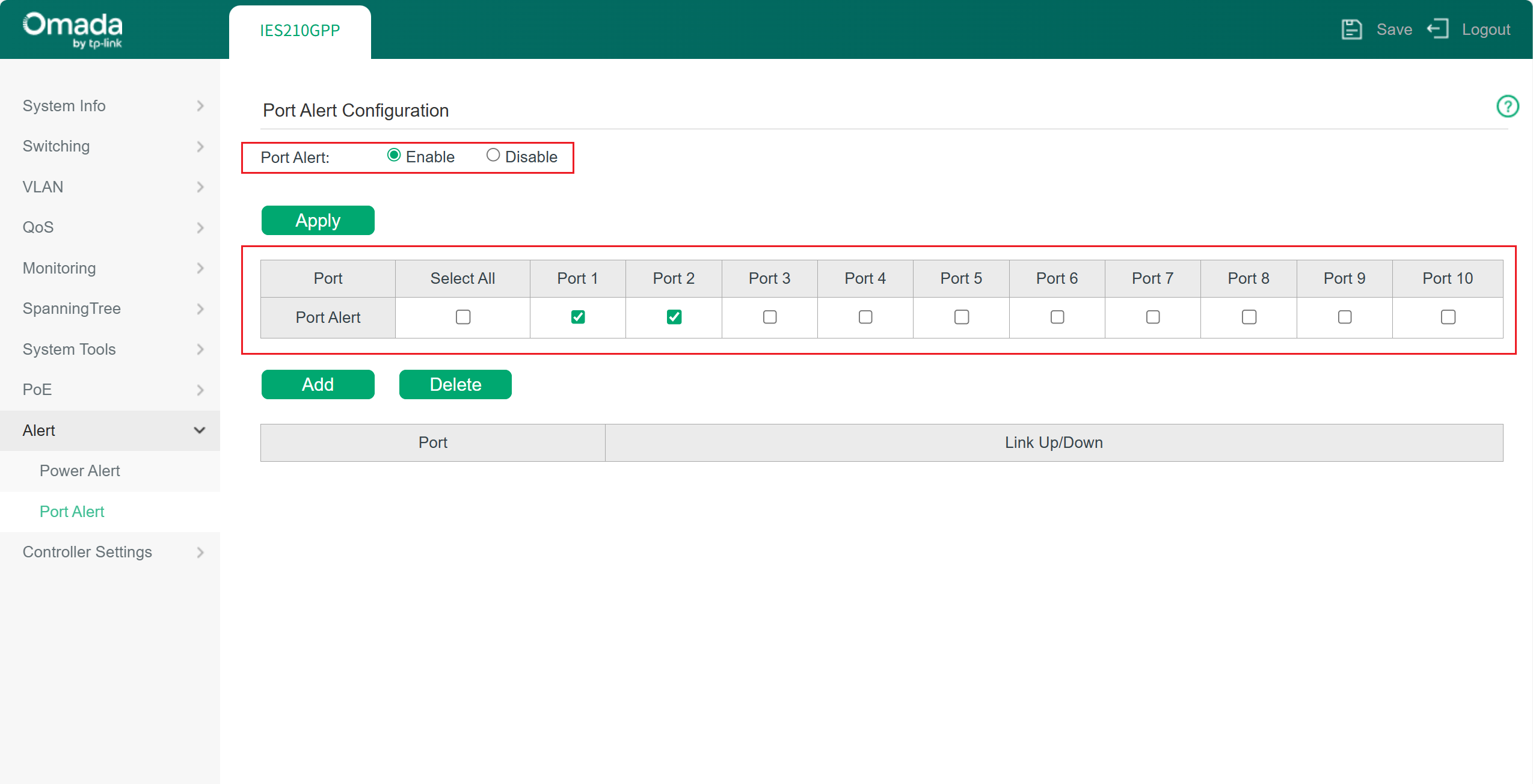
Port Link Down Alarm: Port link down alarm will take effect when a monitored port loses its connection. Be aware that outdated port link down information may be shown here after a modification has been made. You may refresh the web page to acquire the latest accurate information.
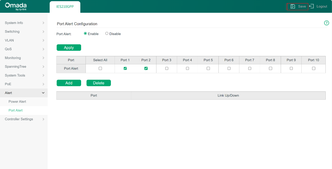
Step 3. Click the Save button in the top-right corner of the page to save the alert settings you have just configured.
Step 4. Connect the alert structure to the switch. Be aware that our industrial switch uses passive relay contacts (dry contact). This means the interface itself does not provide power; it simply acts as a controllable switch. Therefore, when selecting external devices, both the electrical parameters of the relay contact and the actual application scenario must be considered. The middle interface of the phoenix terminal is used to connect a switch, and this interface does not distinguish between positive and negative polarity. Key parameters on this aspect include contact type and maximum switching voltage/current.
Contact Type: Normally Closed (NC). This is the mainstream configuration used in the market, and external devices should be selected according to the required alarm linkage logic.
Maximum Switching Voltage/Current: This refers to the maximum voltage and current that the relay contact can safely switch. For IES series switches, the specification is 24 V / 1 A maximum.
The following components are supported for alarms. And some suggestions when you consider a device to work with an IES switch.
1. Audible/Visual Alarm Devices:
When selecting such devices, ensure that their operating voltage and current are within the switching capacity of the switch’s relay contacts, and that the device type matches the intended alarm linkage logic. Alarm Lights & industrial buzzers units are the most common choices and are typically used to provide immediate on-site alerts to personnel on site.
2. Programmable Logic Controllers (PLC) or Distributed Control Systems (DCS):
The relay output of the switch can be connected to a digital input module of a PLC or DCS. The PLC/DCS monitors the status change of this input and executes predefined control logic, such as starting backup equipment or displaying and recording alarm information.
3. Remote Alarm Systems:
The relay output signal of the switch can also be connected to a dedicated acquisition module. When an alarm is triggered, the module converts the signal into a digital message and reports it to a monitoring system or directly notifies designated personnel. This approach typically requires integration with additional professional alarm platform hardware.
Selection Considerations
- Power Matching
External alarm devices usually require an independent power supply, while the relay contact functions only as a switch. Therefore, the voltage and current of the entire alarm circuit must be calculated carefully, and appropriate power supplies and external devices should be selected to ensure the relay contact is not overloaded.
- Environmental Adaptability
Alarm devices should be selected based on industrial site conditions such as temperature, humidity, vibration, and electromagnetic interference. Industrial-grade devices with suitable IP protection ratings, wide operating temperature ranges, and vibration resistance are recommended.
- Circuit Protection
When connecting inductive loads (such as relay coils or solenoid valves), protective components like flyback diodes should be considered to suppress reverse electromotive force and protect the relay contacts of the switch.
- Intermediate Relay
An intermediate relay may be required when the alarm load current is high, when voltage levels differ, or when NO/NC signal conversion or electrical isolation is needed.
Verification
You may try to simulate fault conditions, such as disconnecting one of the power inputs or unplugging the network cable from a monitored port to confirm whether the alarm is triggered correctly and to check whether the connected external device responds accordingly, as well as whether the alarm status is reflected on the Web interface.
Conclusion
You have now learnt how to set an alarm on Omada industrial switches.
Get to know more details of each function and configuration please go to Download Center to download the manual of your product.
