


How to View the Topology of Complex Switch Configurations in Omada Controller


Contents
STP/RSTP/MSTP Topology Viewing
Introduction
Currently, Omada switches can be configured with some relatively complex features, such as Spanning Tree, M-LAG, and VRRP. Detailed FAQs on how to use these features are already available on the Omada official website. This article primarily introduces how the controller displays these complex topologies.
Requirements
- Spanning tree topology display requires Omada L2 switches/ Omada L3 switches/Omada Pro switches; VRRP topology display requires Omada L3 switches/Omada Pro switches; M-LAG topology display requires Omada Pro switches
- Omada Controller V6.1 and above (some features, such as M-LAG, require Omada Pro Controller)
Configuration
Next, we will introduce the display of Spanning Tree, M-LAG, and VRRP in the controller by chapter.
STP/RSTP/MSTP Topology Viewing
You can configure STP/RSTP using the following FAQ: Spanning Tree Configuration in Omada SDN Controller Mode | TP-Link. For MSTP configuration, refer to this FAQ: How to configure MSTP on L2 Managed switches using the new GUI | Omada Network Support.
RSTP provides the same functionality as STP but with much faster spanning tree convergence, and there is little difference in their configuration. MSTP is an extension of STP and RSTP, blocking ports based on VLANs.
Next, we will use RSTP as an example to build a topology and demonstrate its display in the controller. Suppose the controller has adopted three switches and the intended connection follows the topology below:
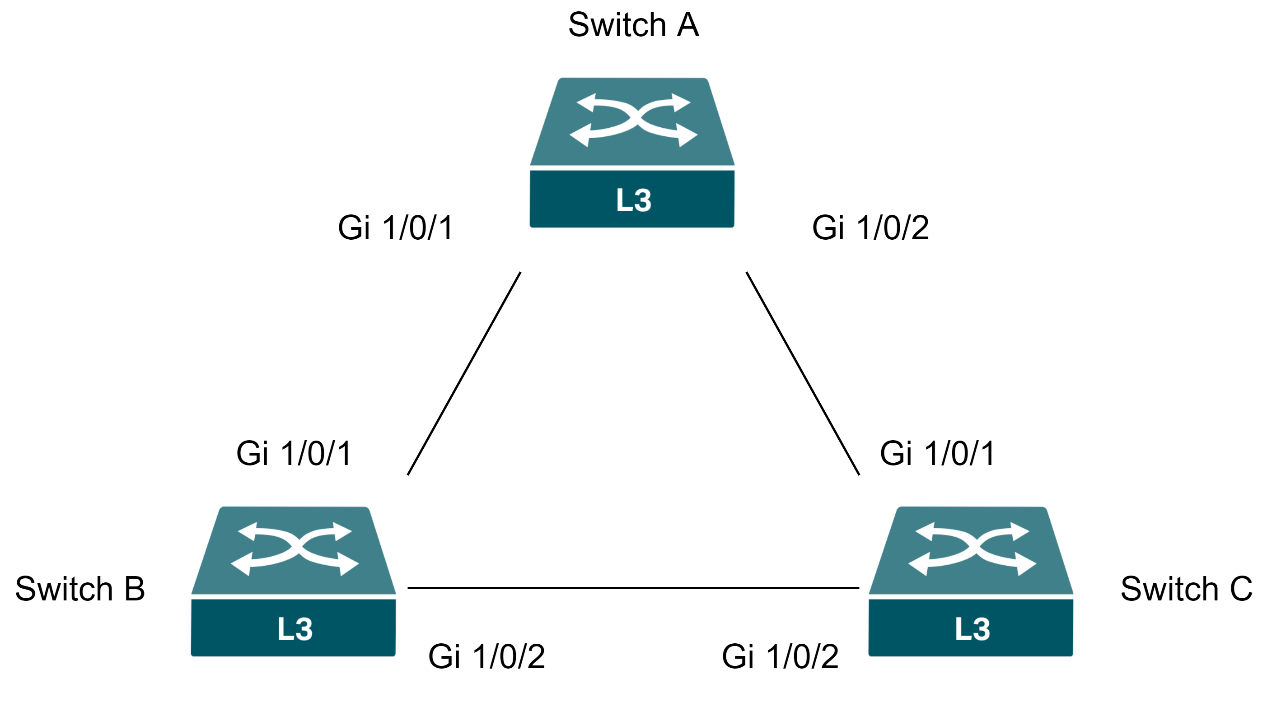
If Spanning Tree or loop detection is not enabled and the switches are connected directly according to the topology above, a loop will be created. To prevent network storms caused by loops, it is necessary to enable the Spanning Tree Protocol globally on all three switches and on the ports connecting them. In this example, we set them all to RSTP. After the configuration is applied and the topology converges, navigate to the Dashboard > Topology in the controller to view the topology. You will observe that the topology has converged to a chain structure. You can also see it shows the loop sign and the blocked loop line.
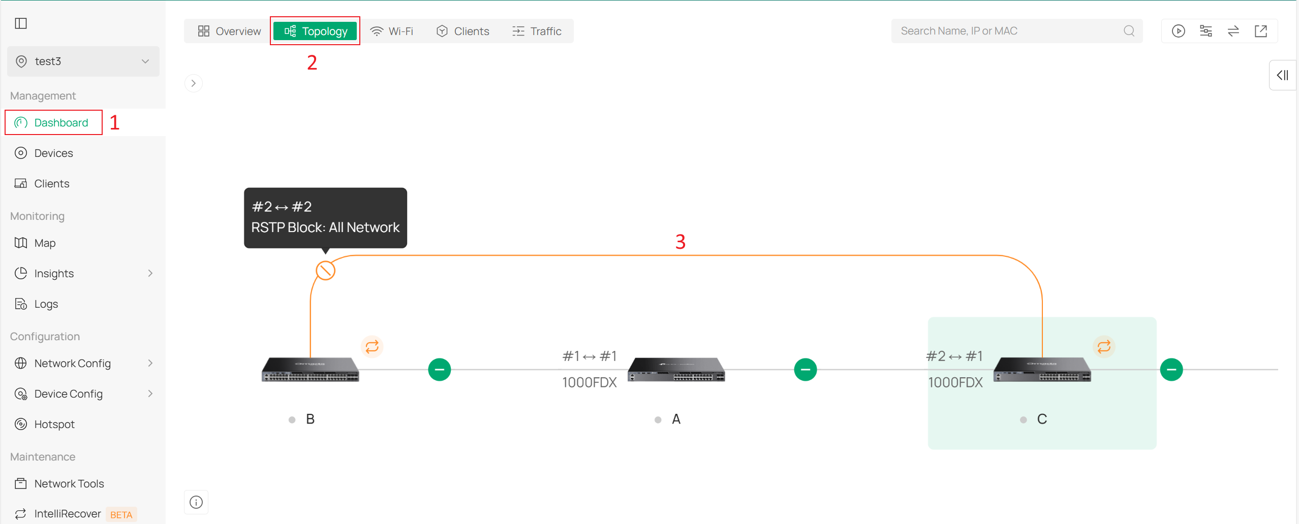
By clicking the switches in sequence, you can see that Port 2 on Switch C is blocked:
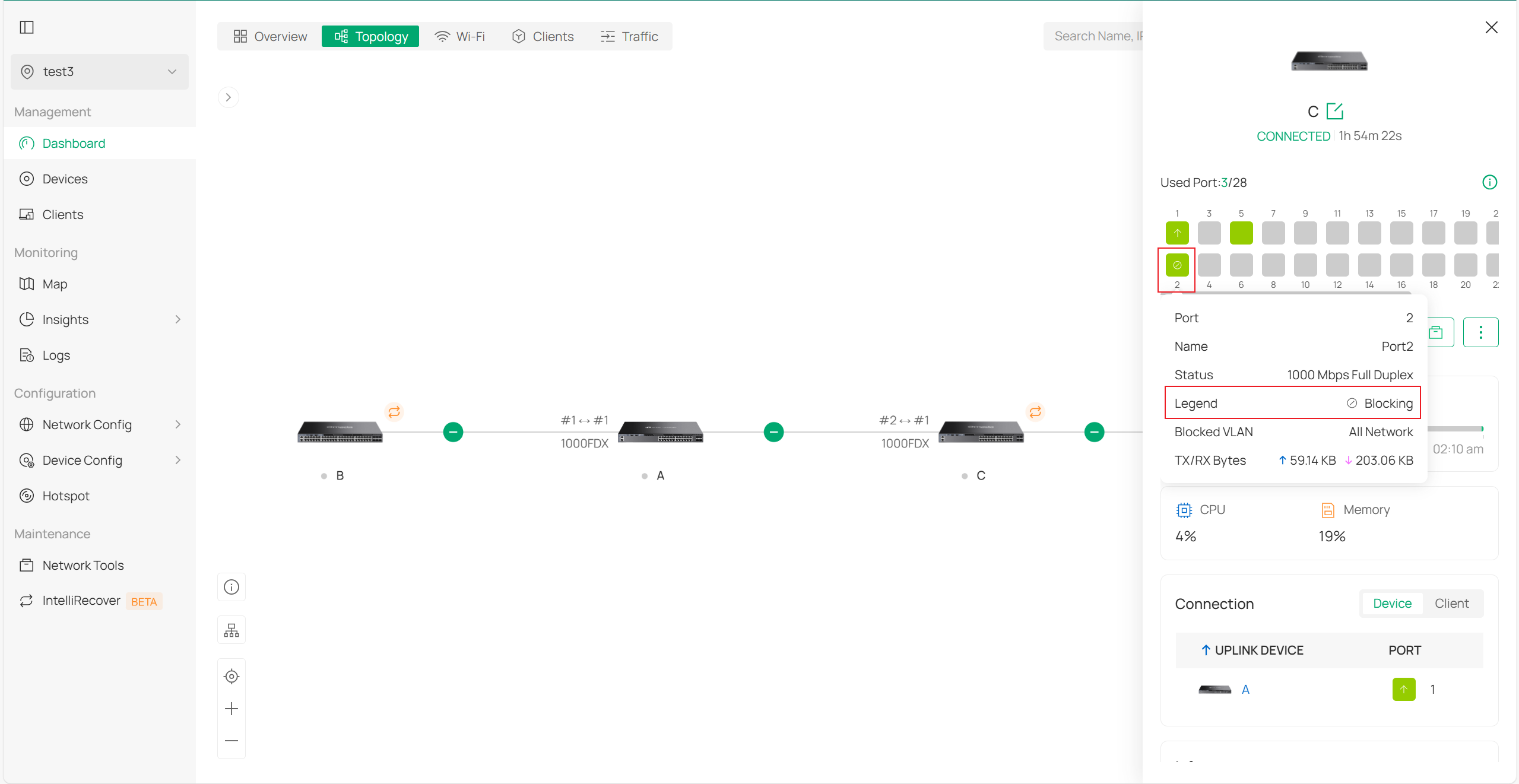
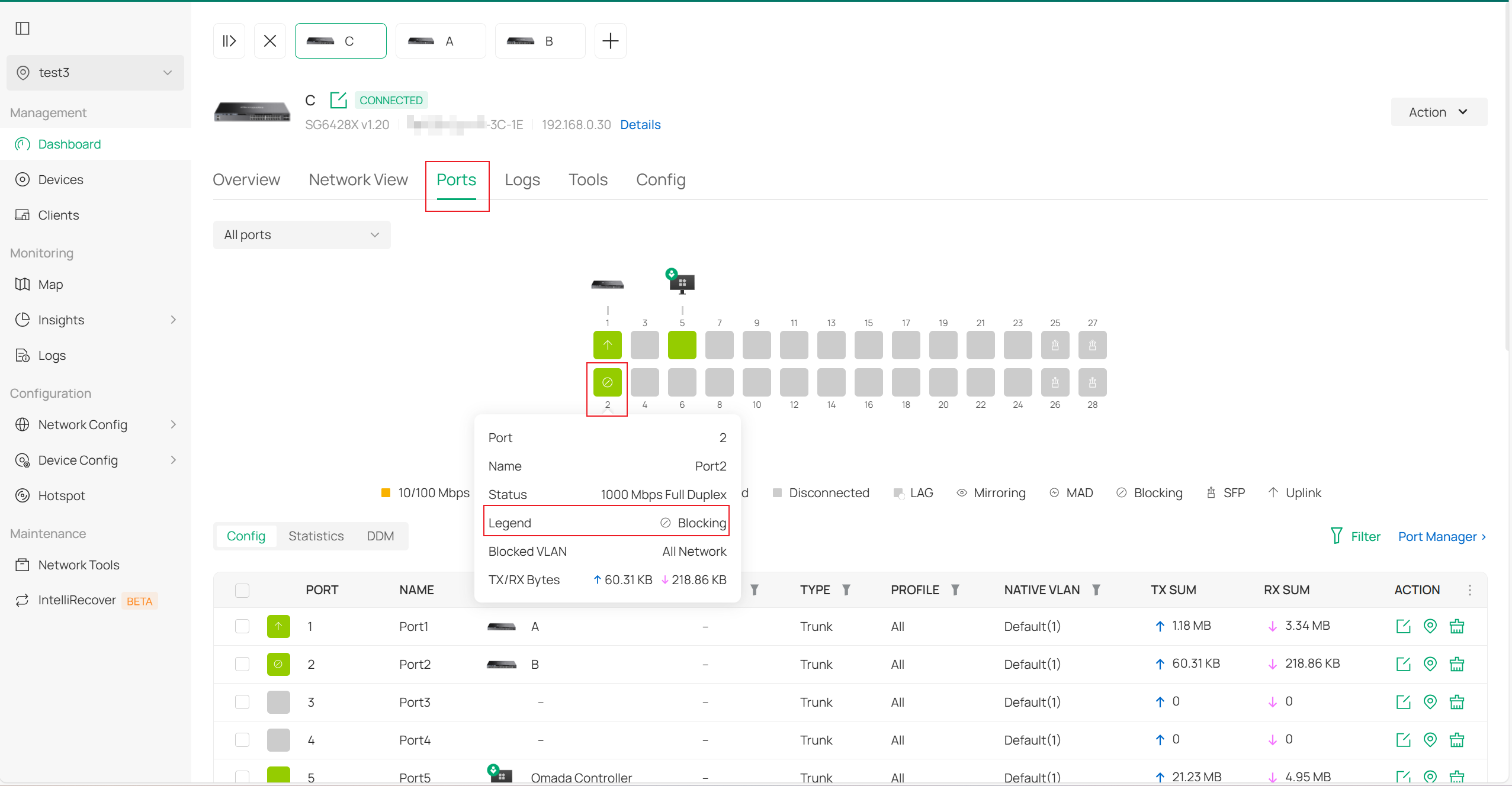
Of course, you can also go to the private configuration interface of Switch C to view the detailed display in the Ports section:
M-LAG Topology Viewing
You can configure M-LAG by following the FAQ below. Please note that this feature is currently only supported by Omada Pro switches and requires the use of an Omada Pro Controller:
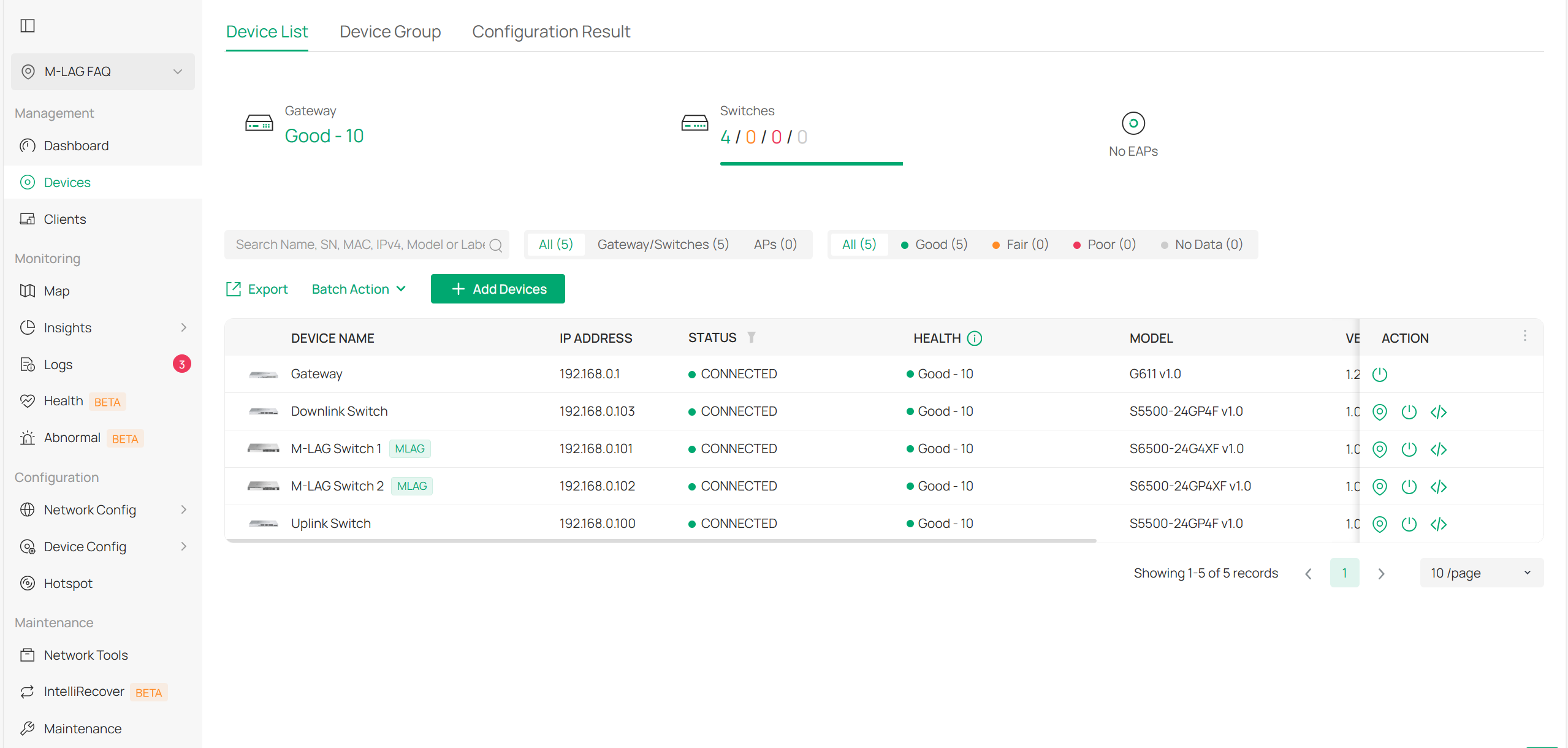
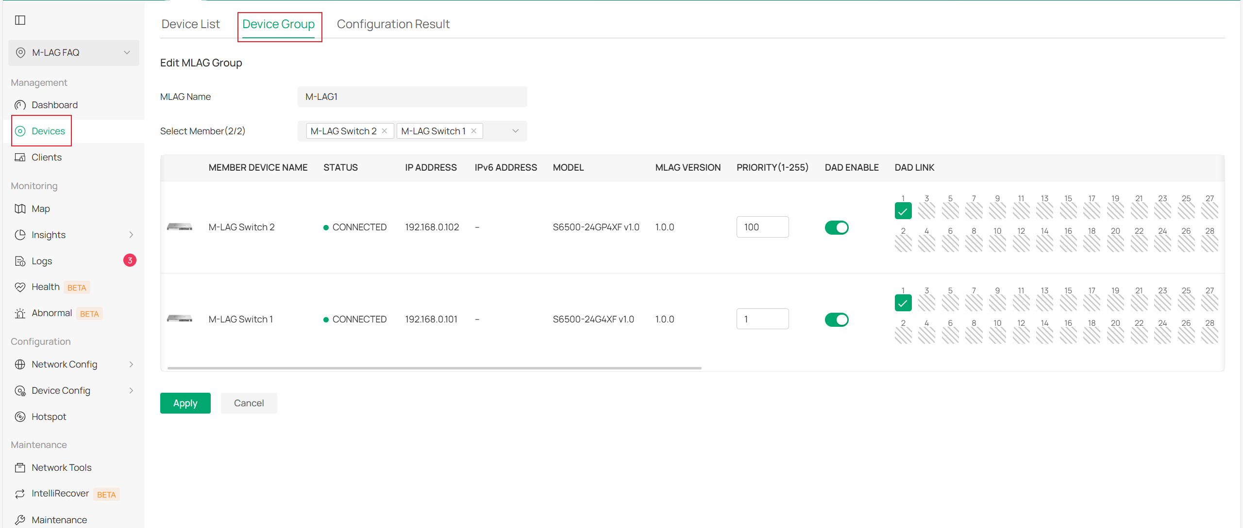
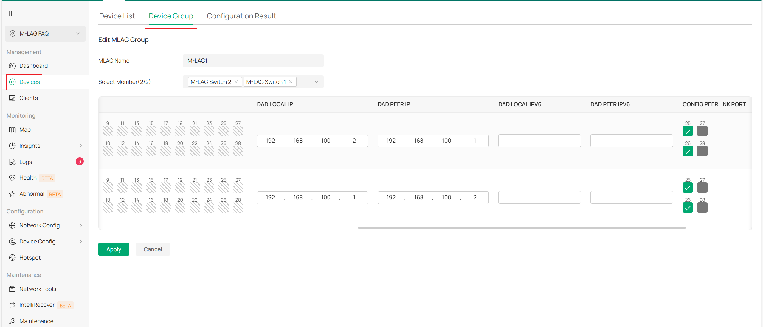
Among these four switches, the upstream switch can be considered the core switch, the two M-LAG switches can be regarded as aggregation layer switches, and the downstream switch can be seen as an access layer switch. Based on the content in the FAQ, the configuration for the two M-LAG switches is as follows:
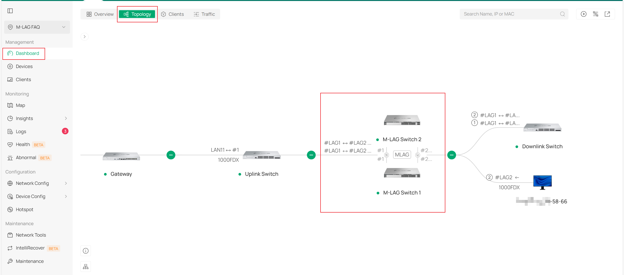
After the configuration is applied and the topology stabilizes, go to Dashboard > Topology in the controller to view the topology. You can also click on the switches in the M-LAG group to view the displayed DAD ports and peerlink ports:
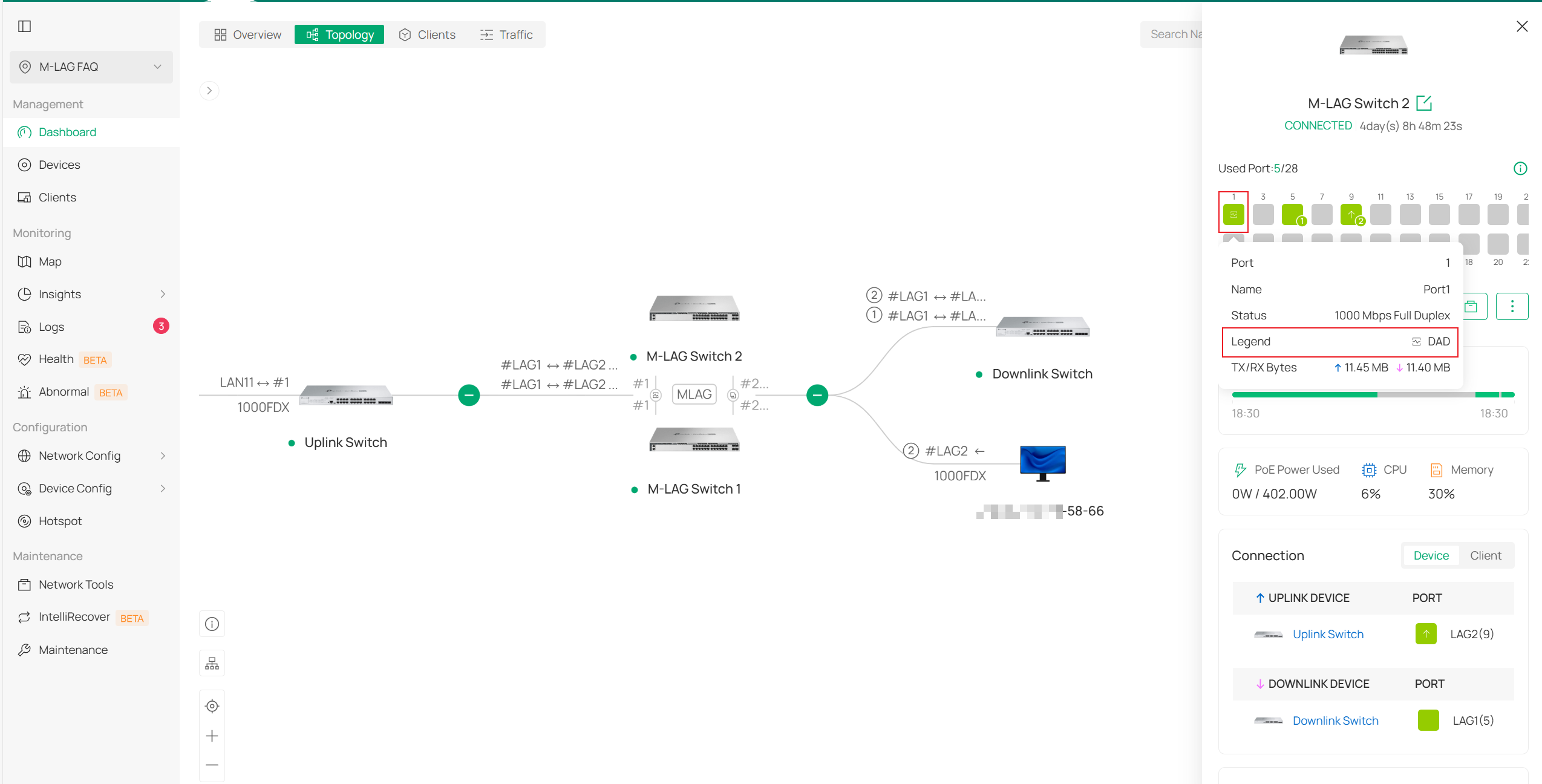
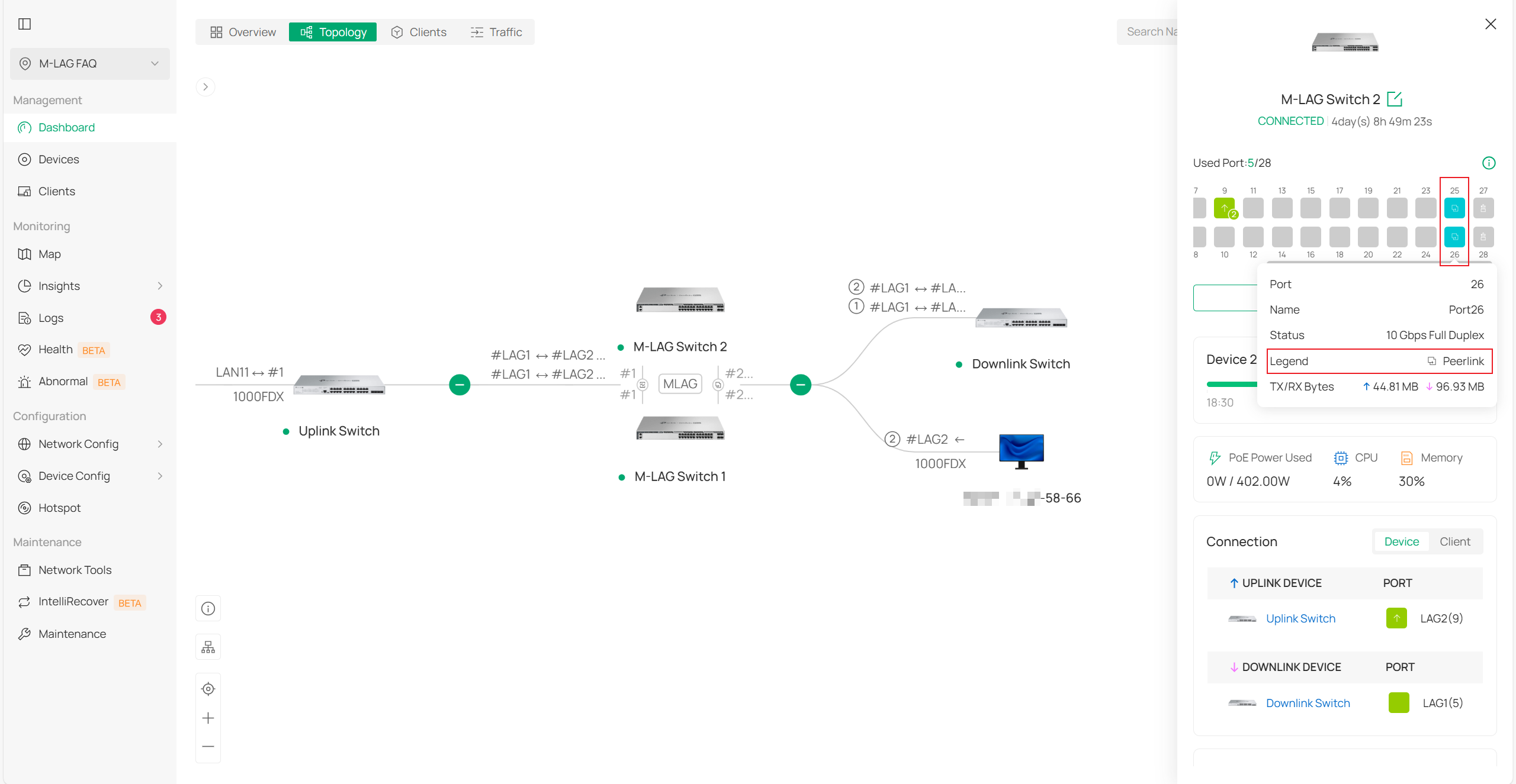
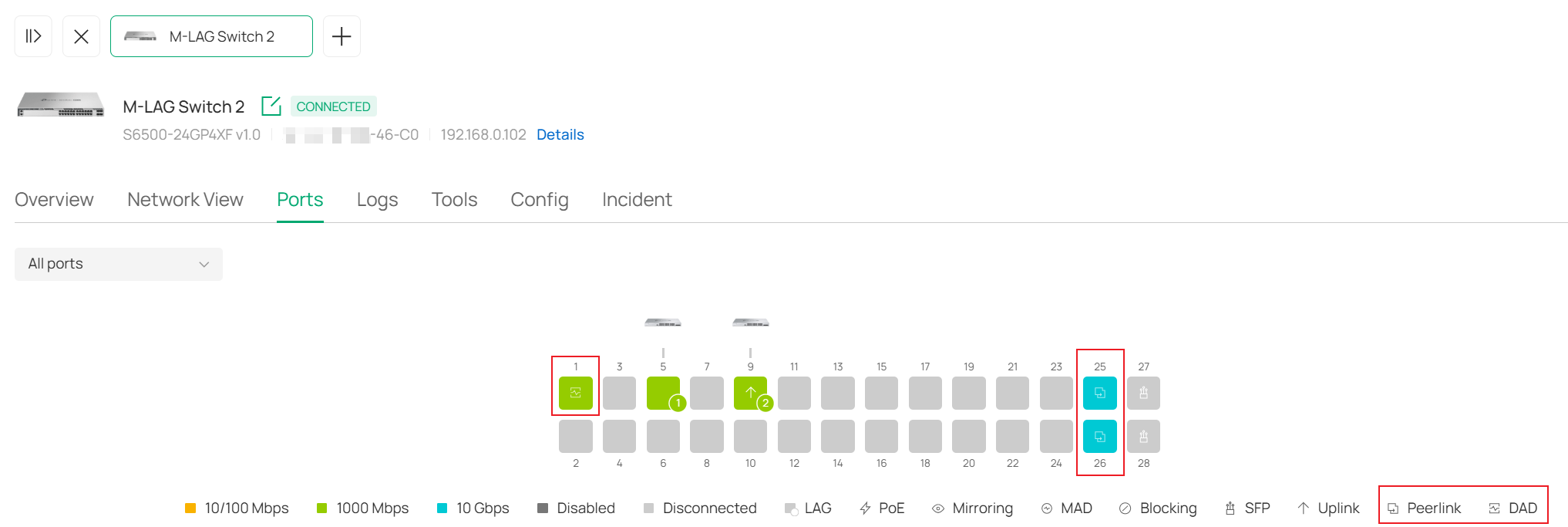
You can also go to the private configuration interface of the switch and view the display of the DAD port and peerlink port in the Ports section.
VRRP Topology Viewing
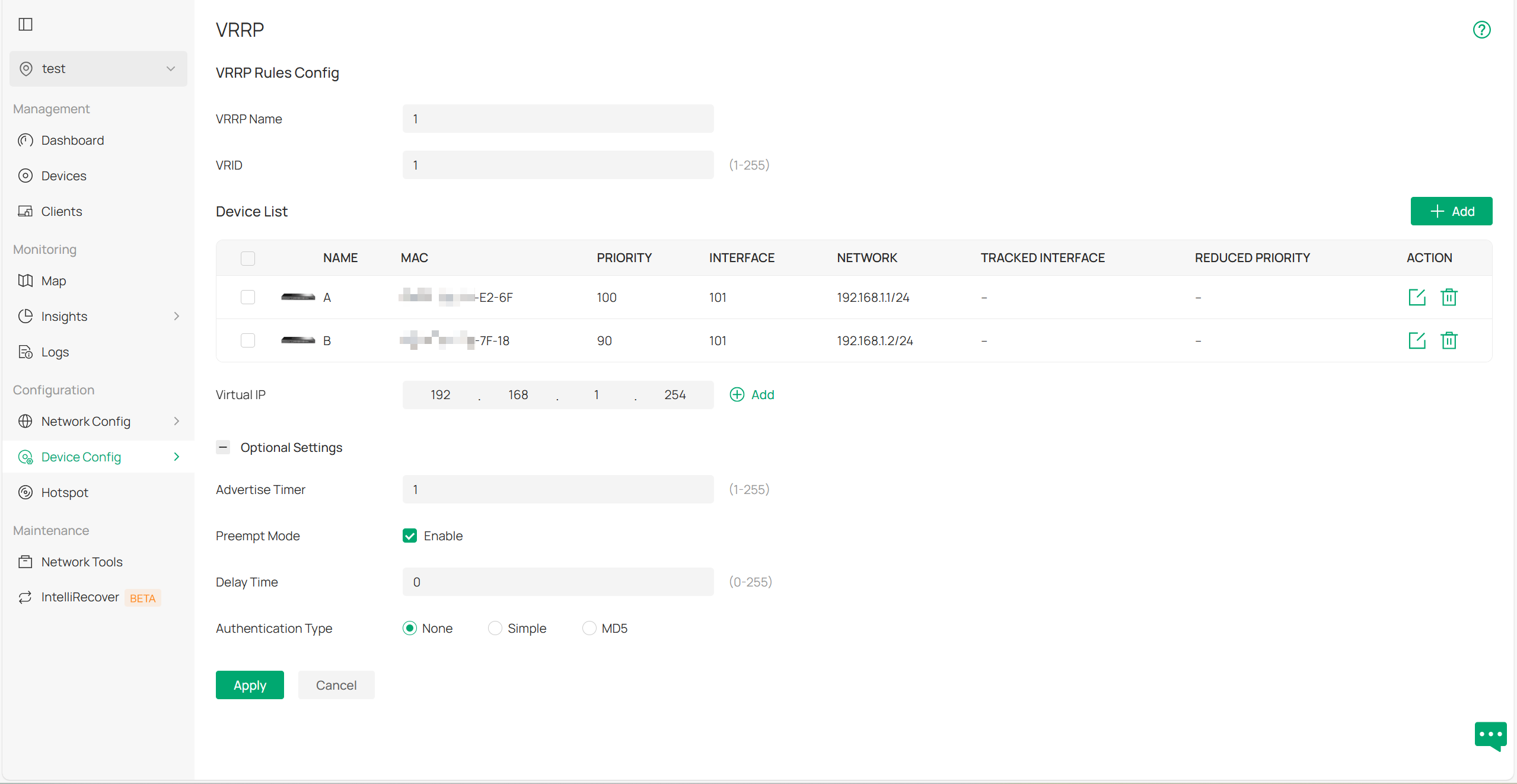
Currently, there is a very detailed FAQ on VRRP: How to configure VRRP on Omada L3 Switches through Omada SDN Controller | Omada Network Support.
Configure VRRP on switches A and B based on the content provided in the FAQ:
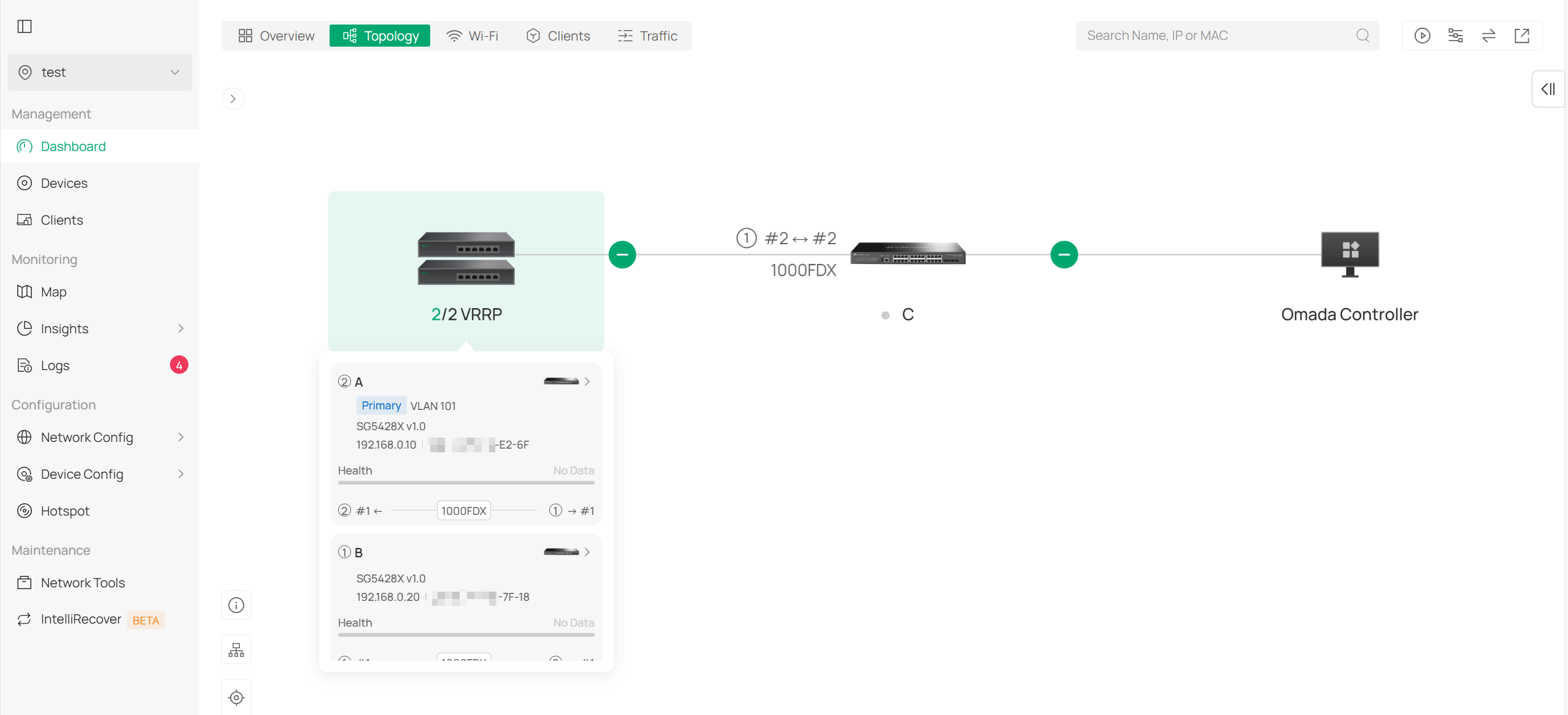
Once the setup is complete and the topology stabilizes, go to Dashboard > Topology in the controller to view the topology. You will notice that switches A and B are displayed as a VRRP group:
Conclusion
This article primarily introduces how the controller displays some relatively complex switch topologies.
Get to know more details of each function and configuration please go to Download Center to download the manual of your product.
