


Omada Switch DHCP Relay Configuration Guide


Contents
Configuration for DHCP Interface Relay
Configuration in Standalone Mode
Configuration in Controller Mode
Configuration for DHCP VLAN Relay
Configuration in Standalone Mode
Configuration in Controller Mode
Configuration for DHCP L2 Relay
Configuration in Standalone Mode
Configuration in Controller Mode
Introduction
Without DHCP Relay, DHCP is only applicable when the DHCP client and server are within the same network segment, and it cannot function across different segments. To dynamically assign IP addresses to devices in multiple network segments, network administrators would typically need to deploy a DHCP server in each segment, which is inefficient. The introduction of DHCP Relay addresses this issue. Clients can use the DHCP Relay to communicate with DHCP servers in other segments, ultimately obtaining legitimate IP addresses. As a result, DHCP clients in multiple segments can utilize a single DHCP server, saving costs and simplifying centralized management.
There are three types of DHCP Relays: DHCP Interface Relay, DHCP VLAN Relay, and DHCP L2 Relay. The most commonly used one is DHCP Interface Relay, which is designed to enable a single DHCP Server to assign IP addresses to DHCP Clients in multiple non-consecutive network segments. In addition to the basic relay functionality, Omada switches offer option for configuring the DHCP Option 82 in DHCP messages. This feature, when used in the relay scenario, allows the DHCP Server to perform more granular operations, such as address allocation, based on the Option 82 feature. Currently, Omada switches provide three actions for processing DHCP messages: Keep, Replace, and Drop.
In conclusion, the three types of DHCP Relays serve the following purposes:
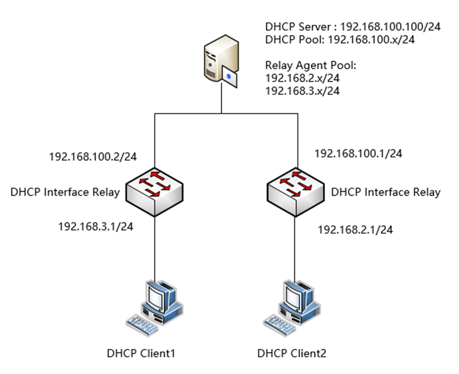
- DHCP Interface Relay: This type of relay acts as a service between DHCP clients and servers in different network segments, forwarding DHCP protocol messages across segments to the target DHCP server. Ultimately, it enables DHCP clients on a network to share a single DHCP server. As illustrated in the figure below, there is only one DHCP server in the network, but multiple relay address pools can be configured. The switches in the intermediate links can then use DHCP Interface Relay to allow each segment to obtain IP addresses from the same DHCP Server while maintaining segmentation between the segments. Without DHCP Relay, DHCP requests from clients in different segments would not be able to reach the DHCP Server.
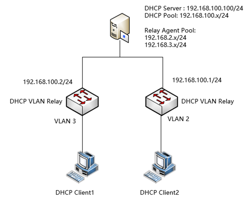
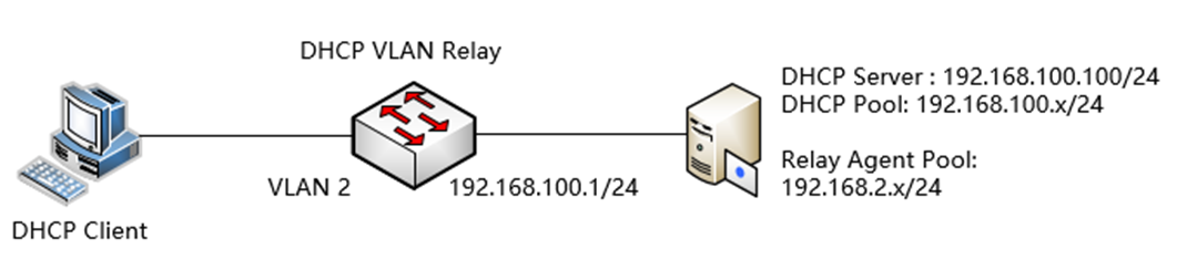
- DHCP VLAN Relay: This type of relay serves a similar purpose as DHCP Interface Relay, with the key difference being that the DHCP clients connected to the relay are not through L3 interfaces but VLANs. In other words, the client and server are not interoperable at layer 3, nor are they connected to the L3 switch. Similar to Interface Relay, as shown in the following figure, clients in different VLANs can obtain IP addresses from the same DHCP server. The allocation of IP addresses to a specific network segment can be determined using Option 82, and the difference here is that the relay switch cannot communicate directly with the clients due to the lack of direct interfaces.
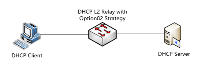
- DHCP L2 Relay: The DHCP clients and servers of this type of relay is within the same local area network (LAN). DHCP L2 Relay enables some L3 relay functionality on L2 devices, only adding the Option 82 feature, which allows attaching Remote Agent ID and other information to the DHCP messages. DHCP Relay Agent typically has routing capabilities and is classified as L3 device. However, in certain network architectures, L2 devices need to be able to attach the Relay Agent Information option information, as terminal networks are often built with L2 devices and connected directly to hosts. These L2 devices do not even have IP addresses, so they cannot directly relay data packets to a DHCP server located in another network. As a result, they attach Option 82 to the DHCP message, allowing the DHCP server to apply address assignment policies based on L2 relay agent information.
This article will introduce how to configure the DHCP (Dynamic Host Configuration Protocol) Relay function both in Standalone mode and Controller mode on the Omada switches that support this function.
Option 82, also known as the Relay Agent Information option, is used to include information about the relay device involved in the DHCP interaction. This information can be used in conjunction with other software to enforce restrictions on DHCP address allocation or implement billing functionalities. Omada switches currently offer three strategies for handling the Option82 field in DHCP messages. After enabling the Option82 feature on a port, the roles are as follows: By default, the Circuit ID in the Option82 value is a combination of the port number and VLAN ID from where the DHCP Request is received. The format is: 0004 + 4 bytes VLAN ID + 1 byte Unit ID + 1 byte Port Number. For example, if a DHCP message is received from Port 1 in standalone mode, the added Option82 Circuit ID would be: 0004000000010101. The Remote ID, on the other hand, defaults to the MAC address of the relay device that received the DHCP Request. It is formatted as: 0006 + 6 bytes DUT's MAC. For instance, if the DHCP message passes through an Omada switch with a MAC address of 00-00-00-00-00-01, the default Option82 RemoteID added would be: 0006000000000001.
Keep: Keep the original Option82 field in the message. If the original message does not have an Option82 field, add the device's default Option82 value or the user-configured value (with the user-configured value taking precedence).
Replace: Replace the Option82 field in the message with the device's default value or the user-configured value.
Drop: If the message contains an Option82 field, discard the message. If not, the message will be relayed normally.
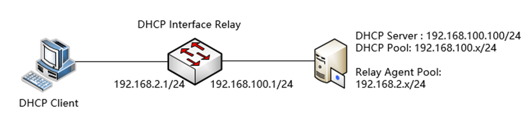
In a DHCP Relay scenario, the DHCP Server needs to assign addresses to clients on different network segments and across network segments. Ordinarily, a DHCP Server can only assign IP addresses within its own network segment. However, it can be configured with multiple Relay Agent Pools to determine the IP subnet to be assigned based on fields like Option82. This requires the DHCP Server to support configuration as a DHCP relay address pool. A common DHCP Server that can perform such operations is Ubuntu's DHCP Server (by installing ISC-DHCP-Server), etc.
Please note that the CLI commands in this article are based on models with 2.5G ports. The command of port is different if using devices with different port speed. For details, please refer to the CLI guide.
Requirements
- All Omada Switches (Excluding Agile and Industrial switches)
- Omada Controller
Configuration for DHCP Interface Relay
The configuration of DHCP Interface Relay will be introduced based on the following topology:
Configuration in Standalone Mode
Step 1. Configure the VLAN and L3 interface connected to the DHCP Client (using a common VLAN interface as an example here). Create VLAN 2 as an example.
Go to L2 FEATURES > VLAN > 802.1Q VLAN > VLAN Config, click the Add button.

Enter VLAN ID, VLAN Name (Optional) and select the Untagged Ports, here we need to configure ports connected to clients as access ports, so we add port 1 and 2 untagged into VLAN 2 as an example. After finished, click Create to finish.
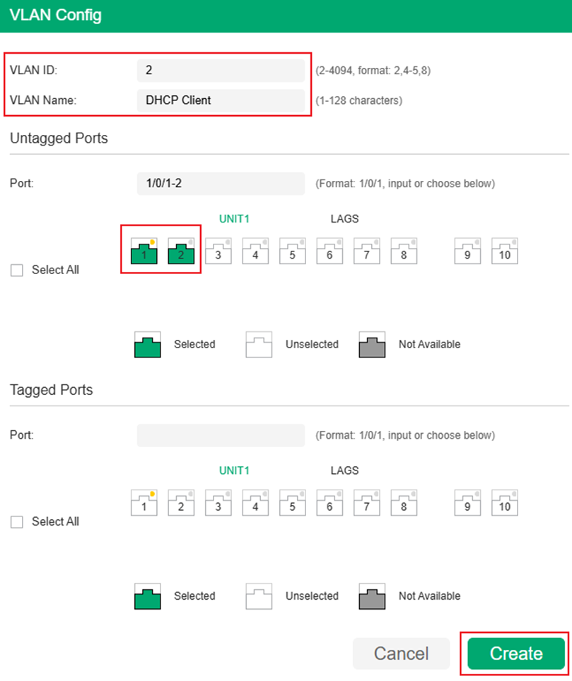
Step 2. Configure the PVID of port 1 and 2 as 2 to make them become the access port of VLAN 2. Go to Port Config, select port 1 and 2, change PVID to 2 and click Apply to save the configuration.

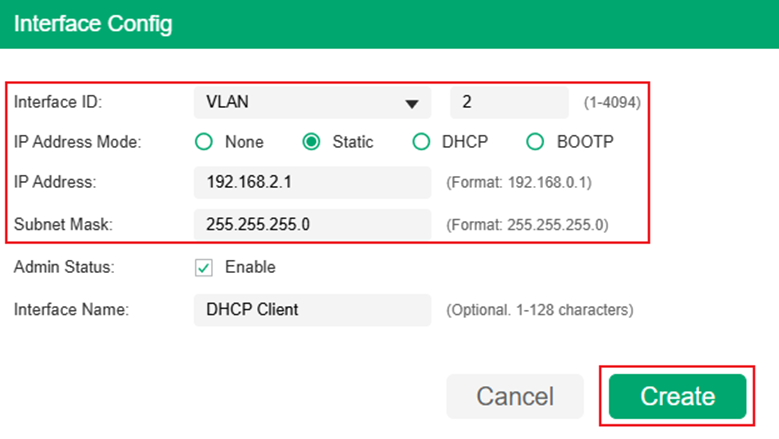
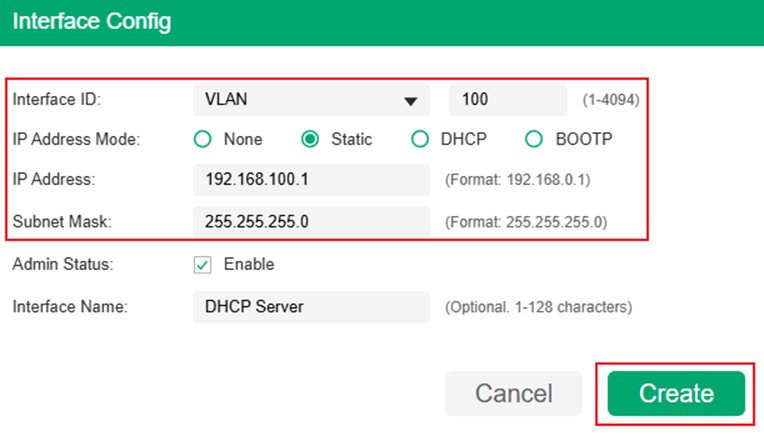
Step 3. Create Layer3 Interface for VLAN 2, go to L3 FEATURES > Interface, click the Add button.
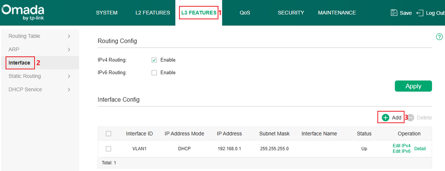
Select Interface Type as VLAN, enter the ID, set IP Address Mode, IP Address and Subnet Mask according to the example topology. Here we set the interface as Static, 192.168.2.1/24, click Create to finish the configuration.
Step 4. Configure the VLAN and L3 interface connected to the DHCP server, create VLAN 100 as example, follow the same procedure as Step 1. As the ports connecting between switches and servers are trunk ports, repeat the steps of creating new VLAN, but add port 9-10 as Tagged ports in this VLAN.
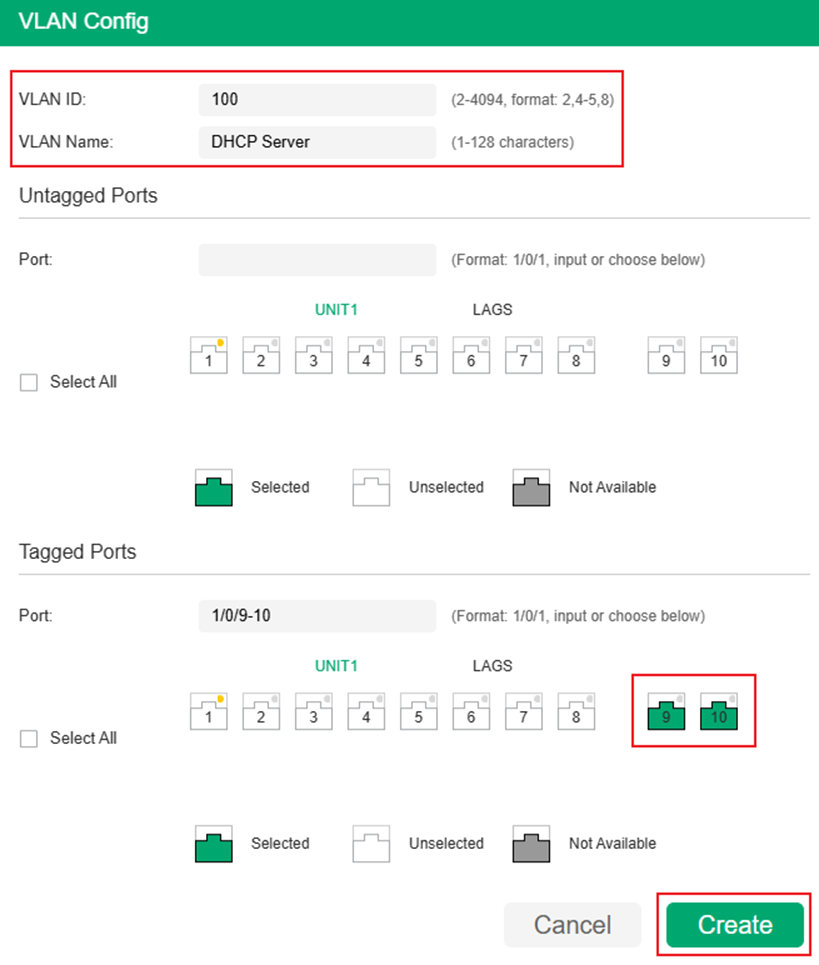
Configure PVID of port 9 and 10 as 100 following the same procedure as Step 1.

Step 5. Follow the same procedure as Step 3 and create the Layer3 Interface for VLAN 100, using Static IP, 192.168.100.1/24 according to the example topology.
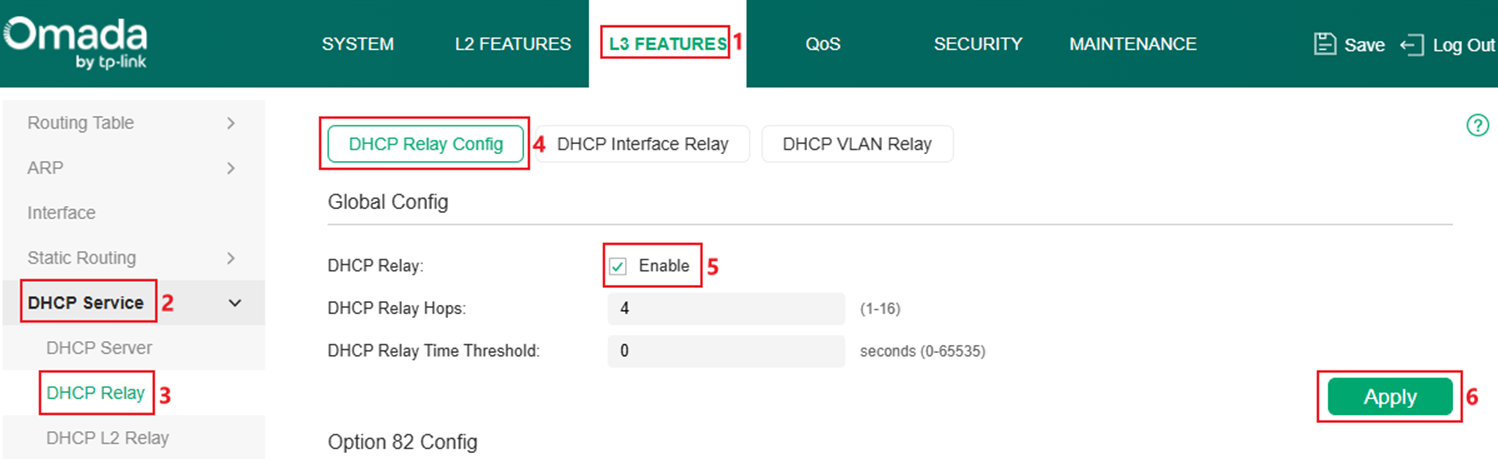
Step 6. Enable DHCP Relay globally. Go to L3 FEATURES > DHCP Service > DHCP Relay > DHCP Relay Config, tick to enable DHCP Relay and click Apply.
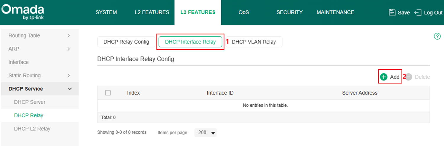
Step 7. Create the DHCP Interface Relay entry, in this example, VLAN 100 interface will help clients in VLAN 2 to relay the DHCP request. Go to DHCP Interface Relay, click the Add button.
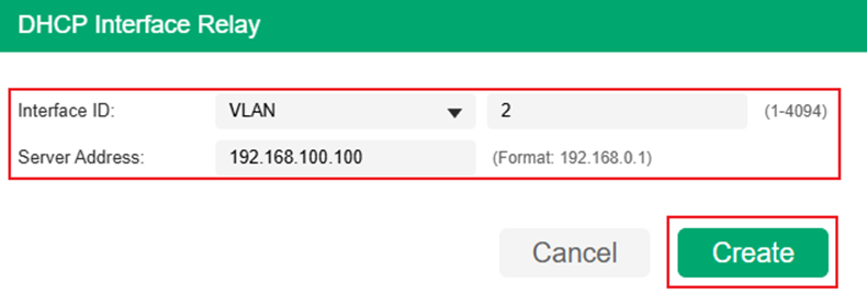
Enter the Interface ID which needs help relaying the DHCP request and the DHCP server address, the switch will automatically choose the interface reachable to the server for helping the relay. In this example, set Interface ID as VLAN 2, Server Address as 192.168.100.100 according to example topology, click Create to finish.
Here, we have finished configuring DHCP Interface Relay in Standalone Mode.
Configuration in Controller Mode
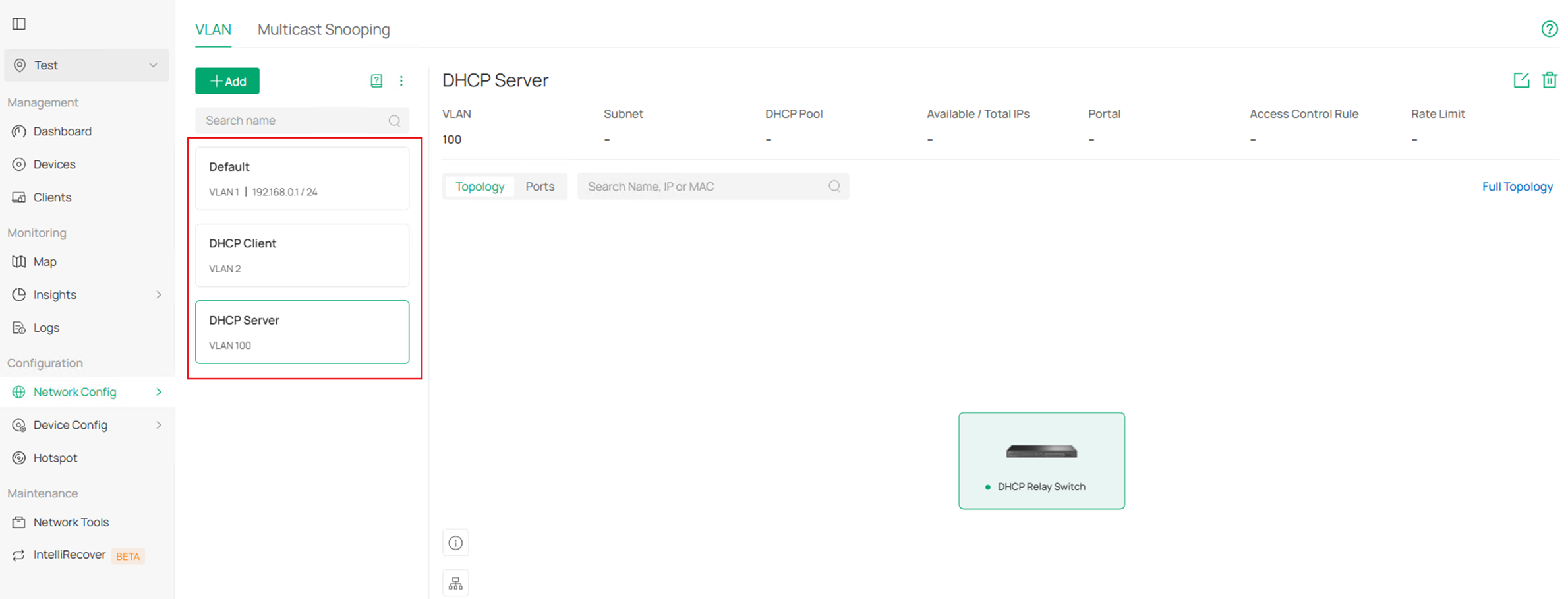
Step 1. Create VLAN for DHCP Client, as an example, create VLAN 2 for client and set the ports 1-2 connecting to clients as access ports of VLAN 2. Go to Network Config > Network Settings > LAN.
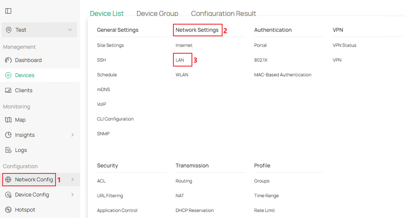
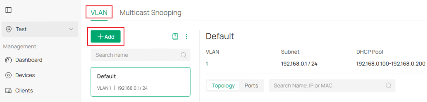
In VLAN section, click Add button to create a new VLAN.
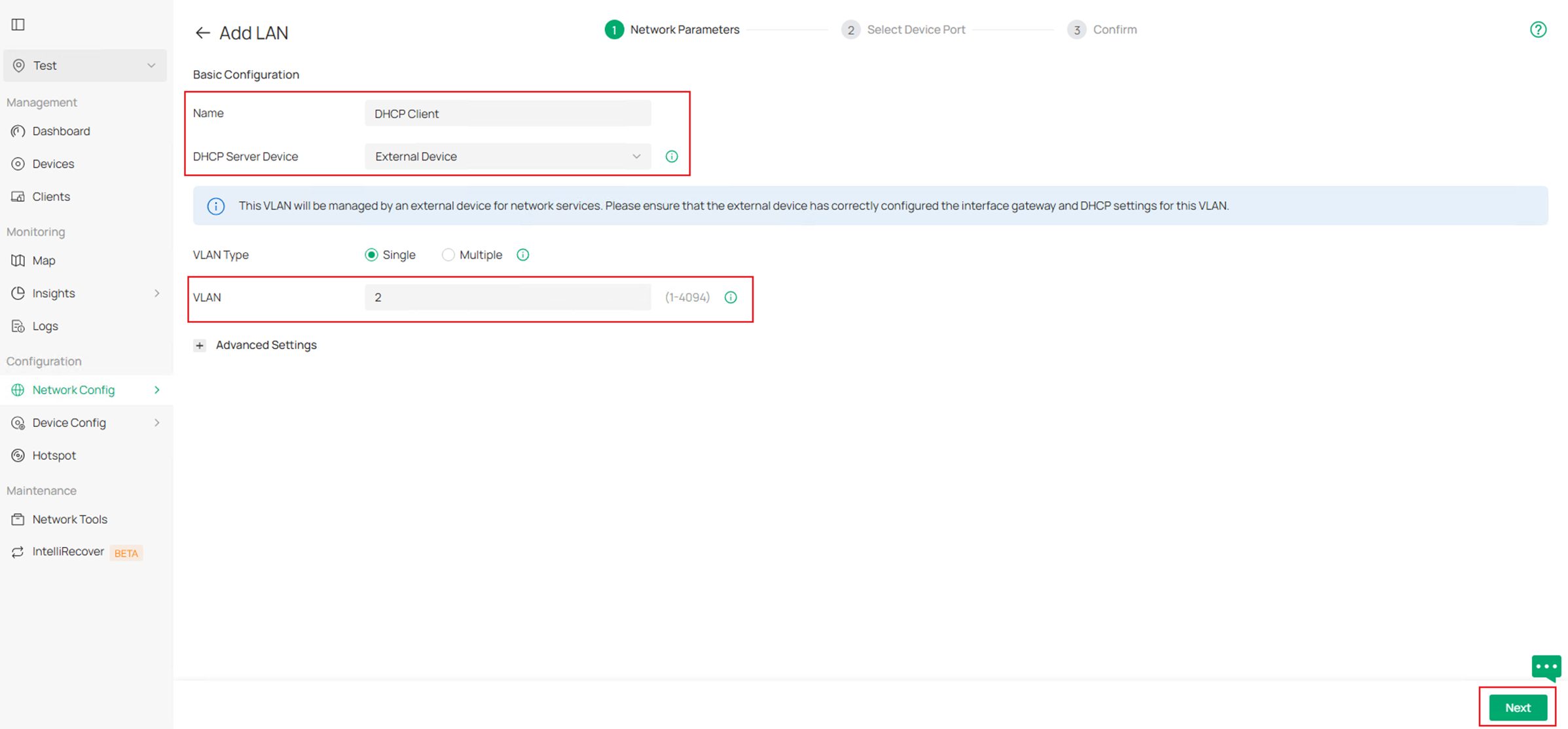
Enter the Name, choose the corresponding DHCP Server Device, in this example, we are using an third-party device as DHCP server, choose External Device as DHCP Server Device, then enter the VLAN ID. Click Next to proceed.

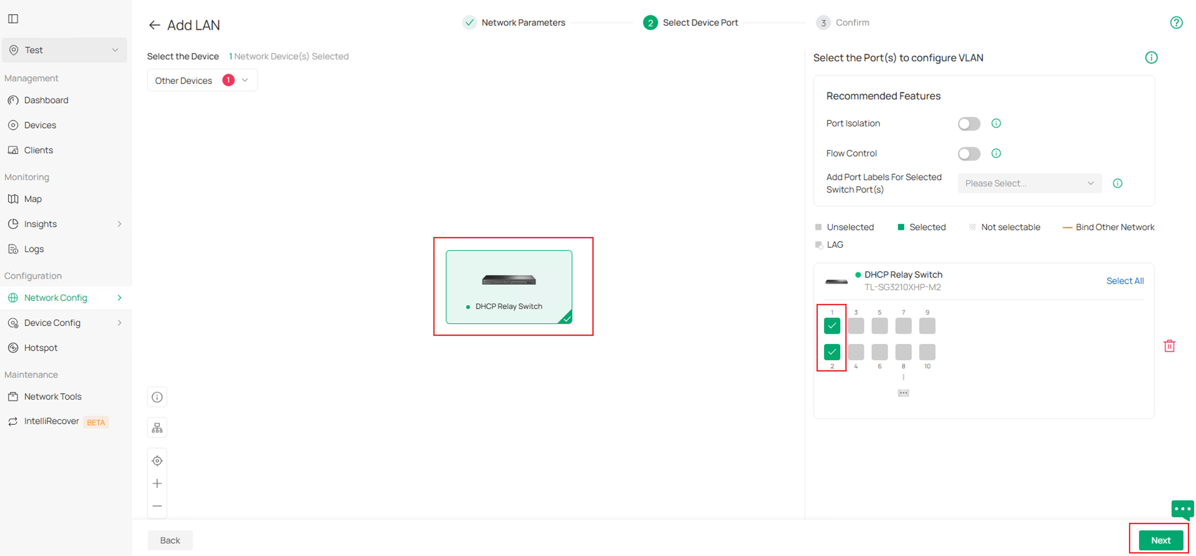
In Select Device Port page, choose the switch and select port 1-2 in this example to quickly configure them as access ports of this VLAN. Click Next to proceed.
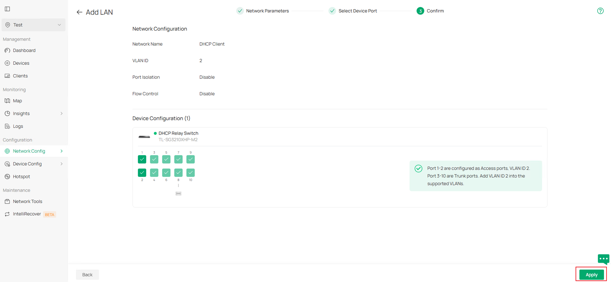
Finally, confirm the VLAN info and click Apply to finish creating the VLAN.

Step 2. Create VLAN for DHCP Server, as an example, create VLAN 100 for the server, as the ports connecting to DHCP Server will be set as trunk port, we could click Skip in Select Device Port page as the ports will be added as tagged into this VLAN automatically. For other configuration, they are the same as Step1. The final result should be like this:

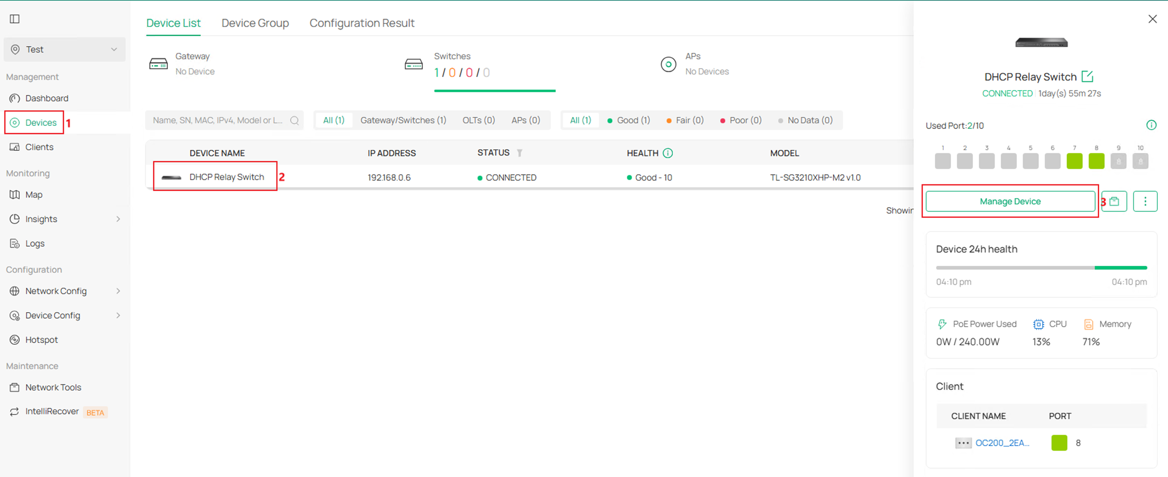
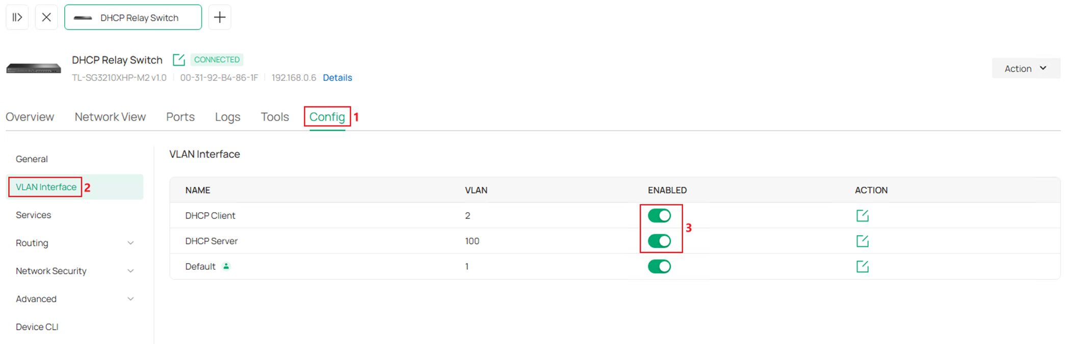
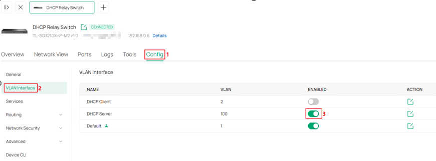
Step 3. Enable VLAN 2 and VLAN 100 interfaces. Go to Devices, click on the switch, then click Manage Device.
Go to Config > VLAN Interface, tick to enable the VLAN Interface for VLAN 2 and 100.
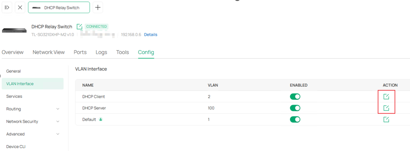
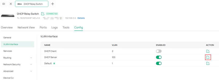
Step 4. Configure IP address and DHCP Mode for the two VLAN Interfaces, according to the example topology, both interface should have static IP configured, and set up the DHCP Relay for VLAN 2 interface. Click Edit button on the interface.
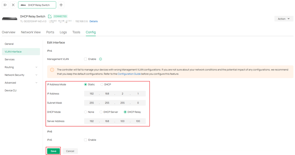
For VLAN 2 interface, set IP Address Mode as Static, enter the IP Address and Subnet Mask as 192.168.2.1/24, set DHCP Mode as DHCP Relay and enter the Server Address. Click Save to finish the configuration.
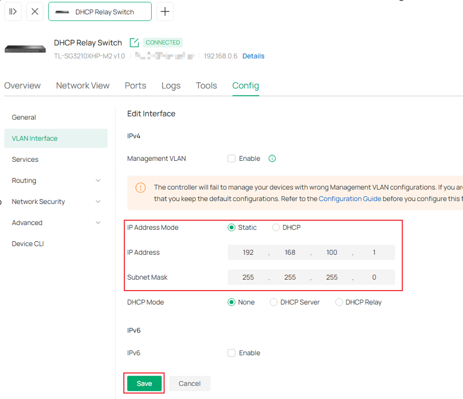
VLAN 100 interface, set IP Address Mode as Static, enter the IP Address and Subnet Mask as 192.168.100.1/24, leave other paramrters as default. Click Save to finish the configuration.
Here, we have finished configuring DHCP Interface Relay in Controller Mode.
Configuration for DHCP VLAN Relay
The configuration of DHCP VLAN Relay will be introduced based on the following topology:
Configuration in Standalone Mode
Step 1. Configure the VLAN and L3 interface connected to the DHCP Client (using a common VLAN interface as an example here). Create VLAN 2 as an example.
Go to L2 FEATURES > VLAN > 802.1Q VLAN > VLAN Config, click the Add button.
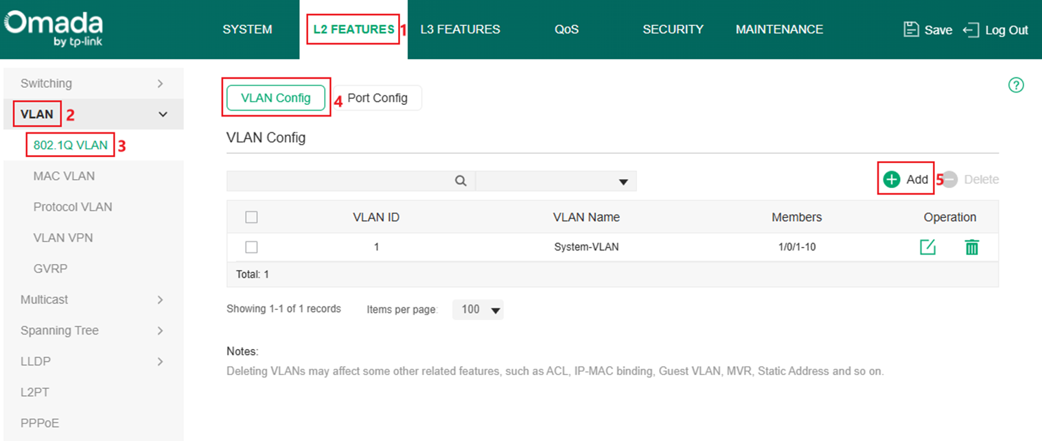
Enter VLAN ID, VLAN Name (Optional) and select the Untagged Ports, here we need to configure ports connected to clients as access ports, so we add port 1 and 2 untagged into VLAN 2 as an example. After finished, click Create to finish.

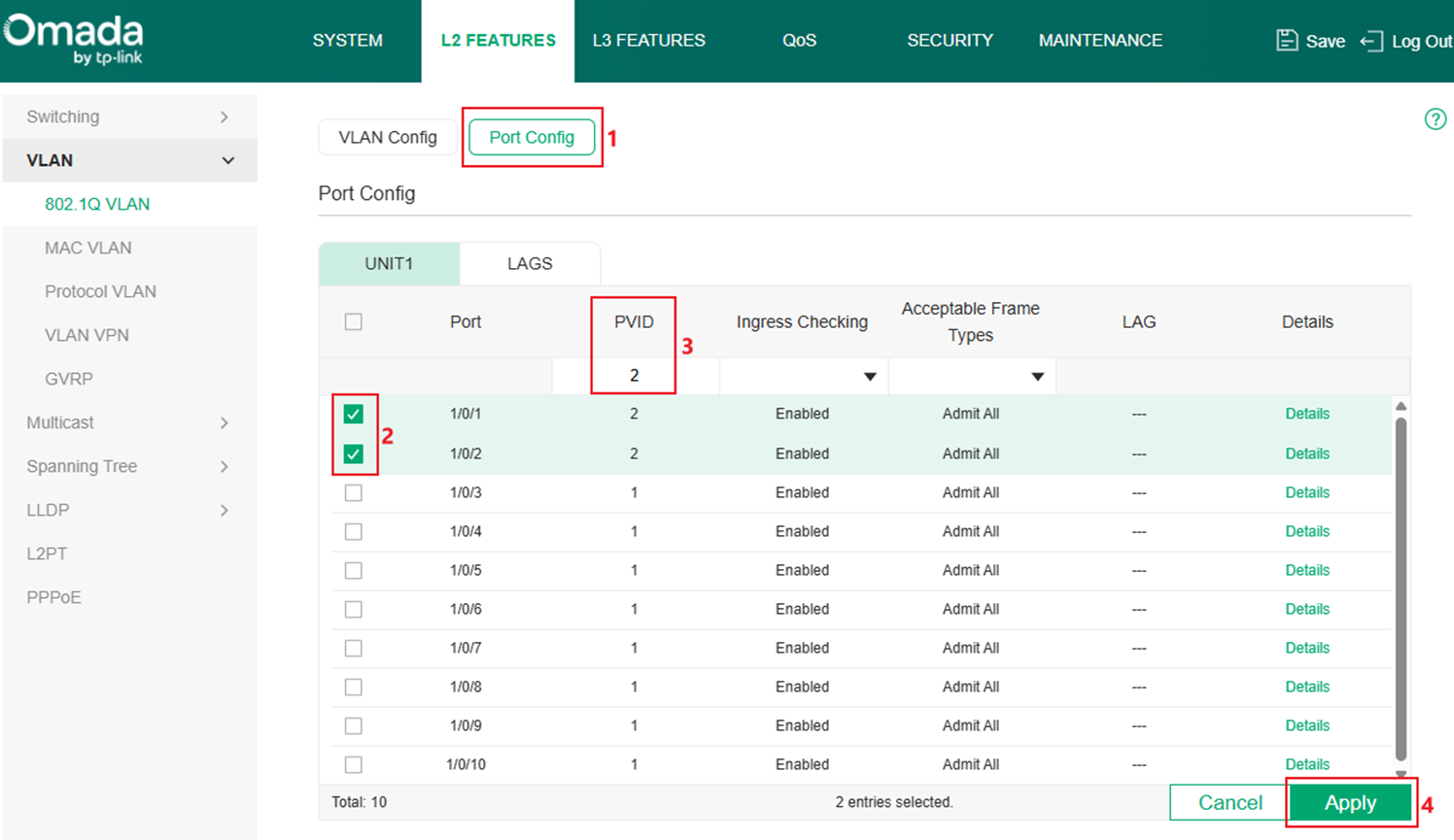
Step 2. Configure the PVID of port 1 and 2 as 2 to make them become the access port of VLAN 2. Go to Port Config, select port 1 and 2, change PVID to 2 and click Apply to save the configuration.
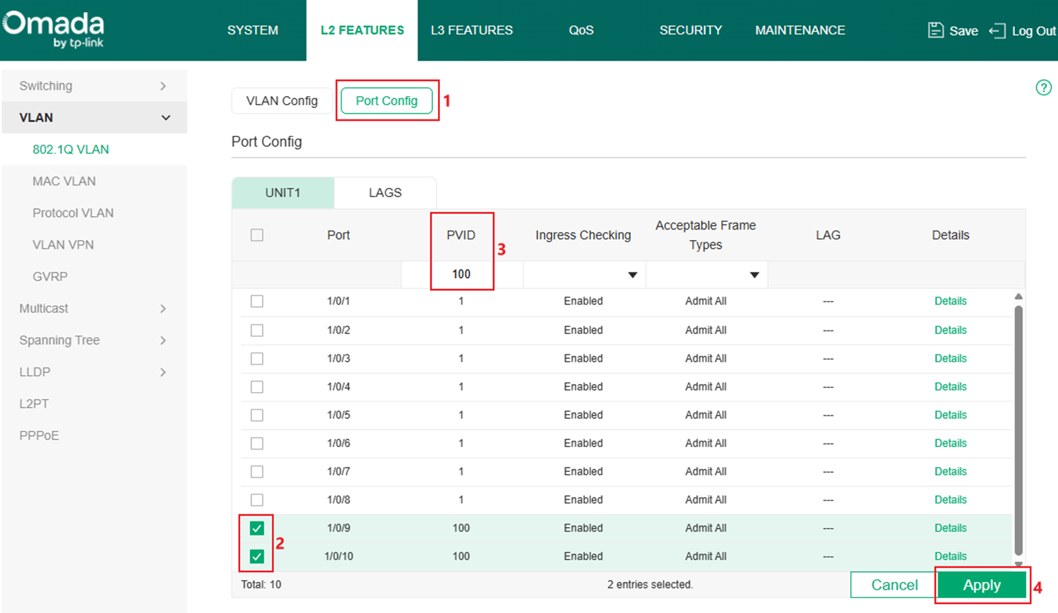
Step 3. Configure the VLAN and L3 interface connected to the DHCP server, create VLAN 100 as example. Follow the same procedure as Step 1. As the ports connecting between switches and servers are trunk ports, repeat the steps of creating new VLAN, but add port 9-10 as Tagged ports in this VLAN.

Configure PVID of port 9 and 10 as 100 following the same procedure as Step 1.
Step 4. Create Layer3 Interface for VLAN 100, go to L3 FEATURES > Interface, click the Add button.

Select Interface Type as VLAN, enter the ID, set IP Address Mode, IP Address and Subnet Mask according to the example topology. Here we set the interface as Static, 192.168.100.1/24, click Create to finish the configuration.

Step 5. Enable DHCP Relay globally. Go to L3 FEATURES > DHCP Service > DHCP Relay > DHCP Relay Config, tick to enable DHCP Relay and click Apply.

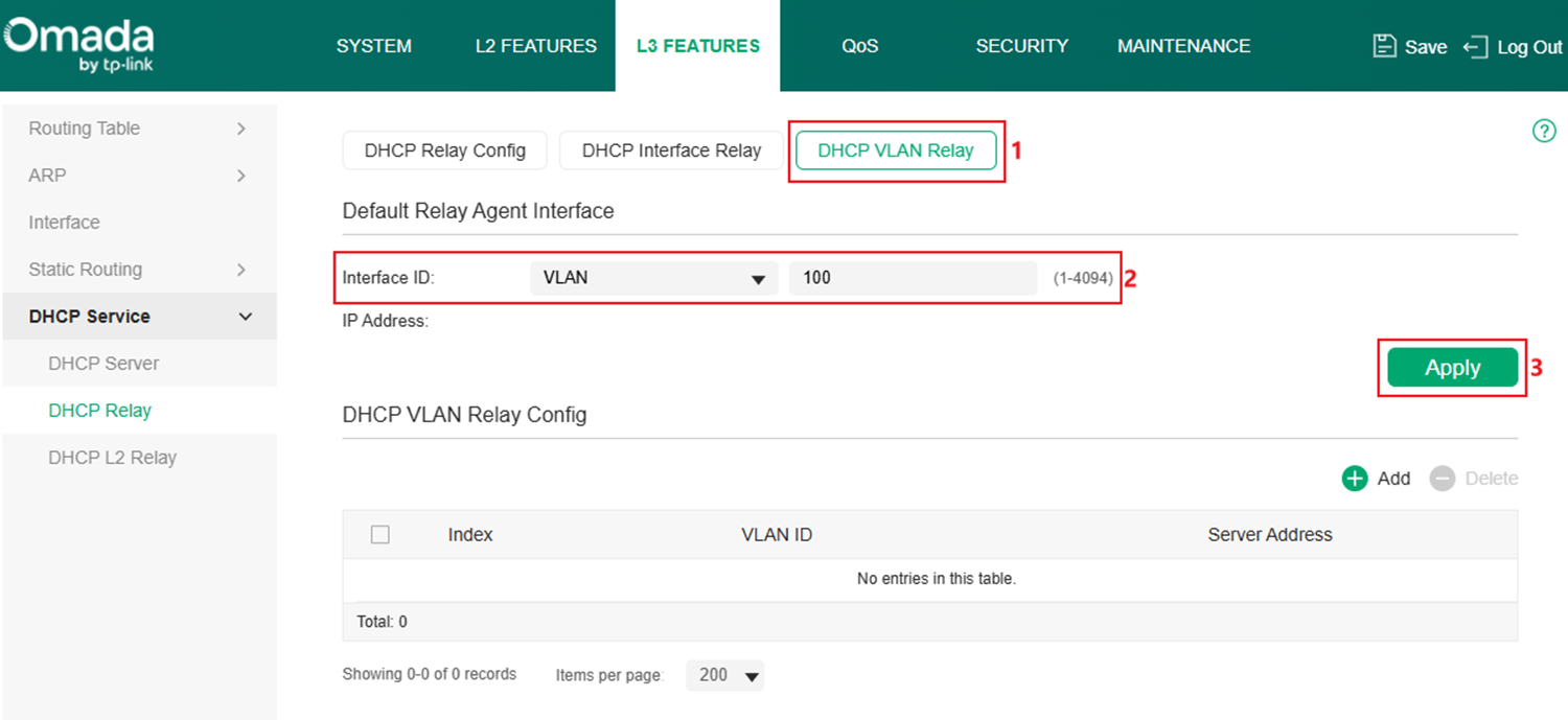
Step 6. Create the DHCP VLAN Relay entry, in this example, VLAN 100 interface will help clients in VLAN 2 to relay the DHCP request. Go to DHCP VLAN Relay, set VLAN 100 interface as the Default Relay Agent Interface, click Apply to finish.
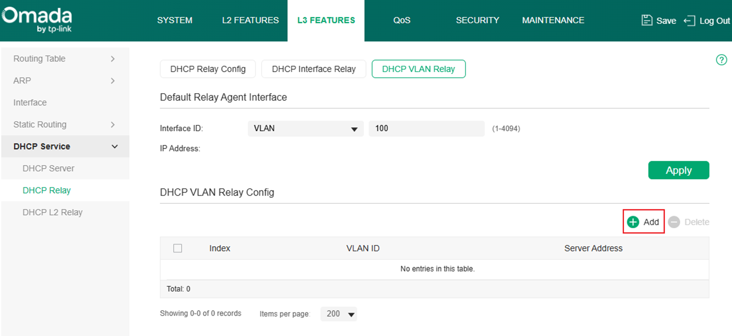
Click the Add button to add an DHCP VLAN Relay entry.
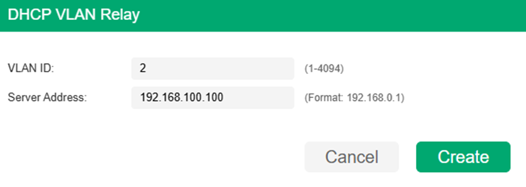
Enter the VLAN ID which needs help relaying the DHCP request and the DHCP server address, the switch will use the Default Relay Agent Interface configured to relay the DHCP request towards DHCP server. In this example, set VLAN ID as VLAN 2, Server Address as 192.168.100.100 according to example topology, click Create to finish.
Here, we have finished configuring DHCP VLAN Relay in Standalone Mode.
Configuration in Controller Mode
Step 1. Create VLAN for DHCP Client, as an example, create VLAN 2 for client and set the ports 1-2 connecting to clients as access ports of VLAN 2. Go to Network Config > Network Settings > LAN.

In VLAN section, click Add button to create a new VLAN.

Enter the Name, choose the corresponding DHCP Server Device, in this example, we are using an third-party device as DHCP server, choose External Device as DHCP Server Device, then enter the VLAN ID. Click Next to proceed.
In Select Device Port page, choose the switch and select port 1-2 in this example to quickly configure them as access ports of this VLAN. Click Next to proceed.

Finally, confirm the VLAN info and click Apply to finish creating the VLAN.
Step 2. Create VLAN for DHCP Server, as an example, create VLAN 100 for the server, as the ports connecting to DHCP Server will be set as trunk port, we could click Skip in Select Device Port page as the ports will be added as tagged into this VLAN automatically. For other configuration, they are the same as Step1. The final result should be like this:
Step 3. Enable VLAN 100 interface for DHCP Server. Go to Devices, click on the switch, then click Manage Device.

Go to Config > VLAN Interface, tick to enable the VLAN Interface for VLAN 100.
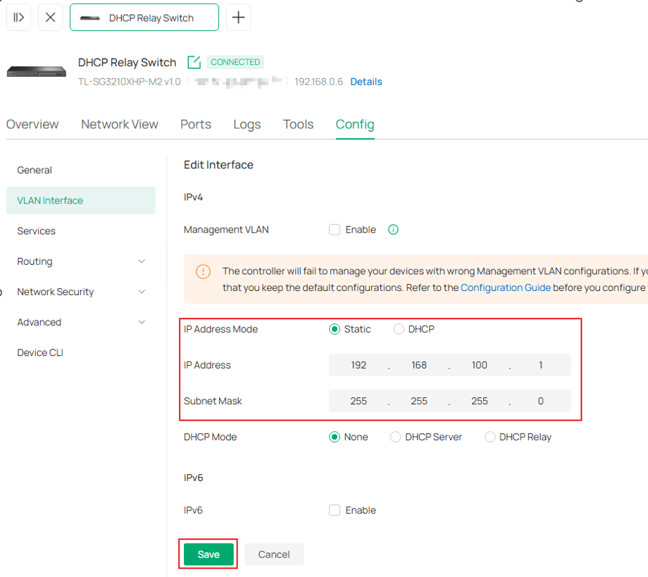
Step 4. Configure IP address for DHCP Server VLAN Interface, according to the example topology, it should have static IP configured. Click Edit button on the interface.
VLAN 100 interface, set IP Address Mode as Static, enter the IP Address and Subnet Mask as 192.168.100.1/24, leave other paramrters as default. Click Save to finish the configuration.
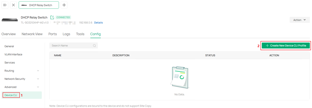
Step 5. The DHCP VLAN Relay part needs to be deployed via CLI Template, go to Device CLI in Config. Click Create New Device CLI Profile.
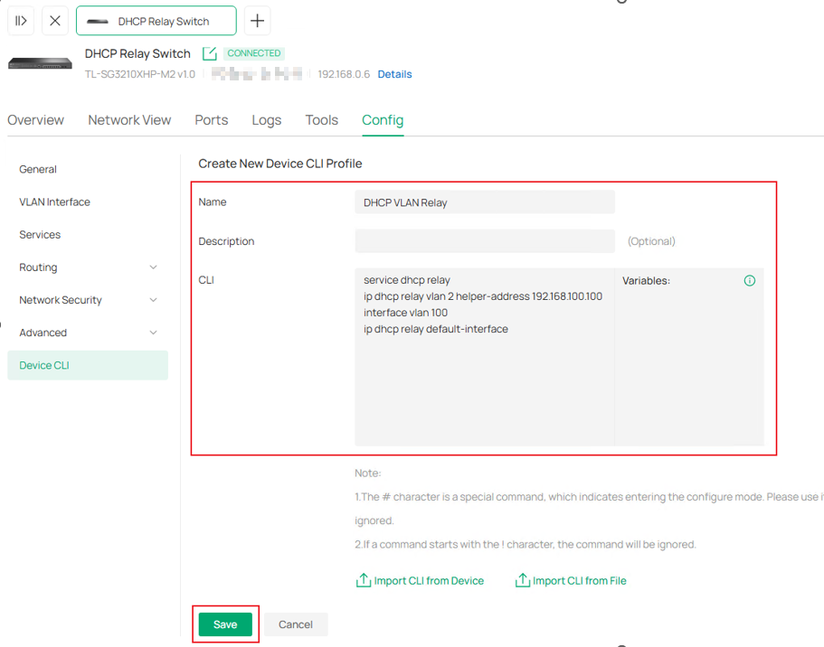
Name this template and enter the commands, in this example, we are using VLAN 100 interface to help VLAN 2 device forward DHCP request, so VLAN 100 is set as DHCP VLAN Relay default-interface and DHCP server IP address needs to be set as helper-address for VLAN 2. Commands as follows:
service dhcp relay
ip dhcp relay vlan 2 helper-address 192.168.100.100
interface vlan 100
ip dhcp relay default-interface
Click Save to proceed.
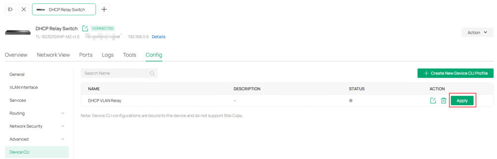
Step 5. Click Apply to push this CLI template command to device.
Here, we have finished configuring DHCP VLAN Relay in Controller Mode.
Configuration for DHCP L2 Relay
The configuration of DHCP L2 Relay will be introduced based on the following topology:
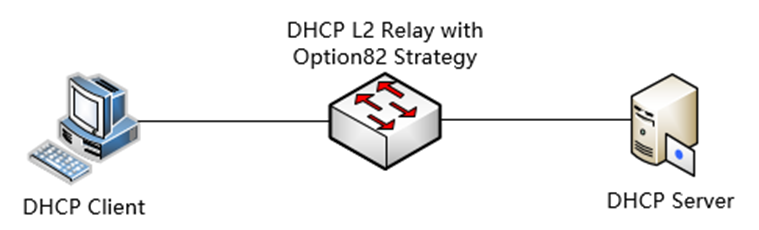
Configuration in Standalone Mode
This section describes the configuration steps.
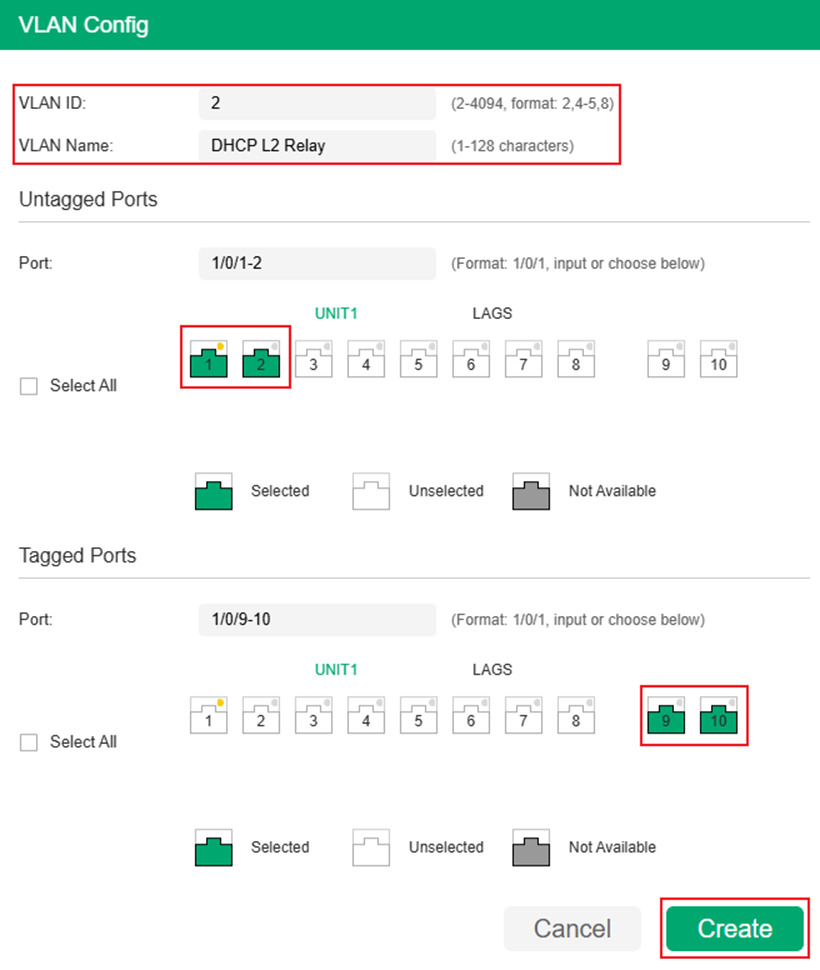
Step 1. Configure the VLAN connecting DHCP client and server. For the communication between a client and a server within the same LAN, they only need to be planned in the same VLAN. Here we take their interaction in VLAN 2 as an example. The client is connected through an access port, while the server is connected through a trunk port. Create VLAN 2 and add port 1-2 as Untagged, port 9-10 as Tagged. Go to L2 FEATURES > VLAN > 802.1Q VLAN > VLAN Config, click the Add button.

Enter VLAN ID, VLAN Name (Optional) and select the Untagged and Tagged Ports, After finished, click Create to finish.
Step 2. Configure the PVID of port 1 and 2 as 2 to make them become the access port of VLAN 2. Go to Port Config, select port 1 and 2, change PVID to 2 and click Apply to save the configuration.

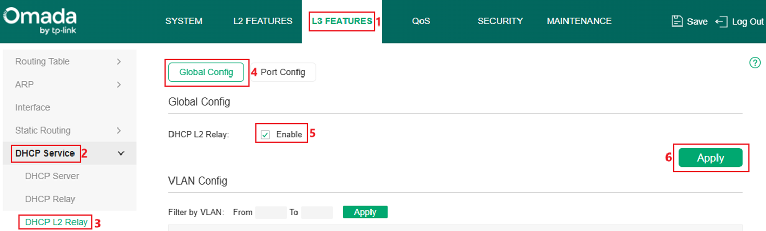
Step 3. Enable DHCP L2 Relay globally. Go to L3 FEATURES > DHCP Service > DHCP L2 Relay > Global Config. Tick to enable DHCP L2 Relay, click Apply to save the configuration.
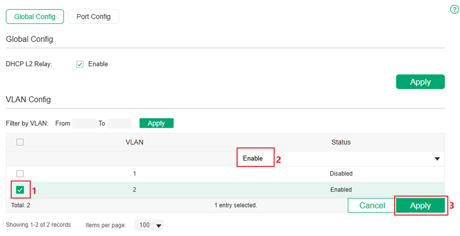
Step 4. In VLAN Config, select the corresponding VLAN and change the status to Enabled. Click Apply to save.
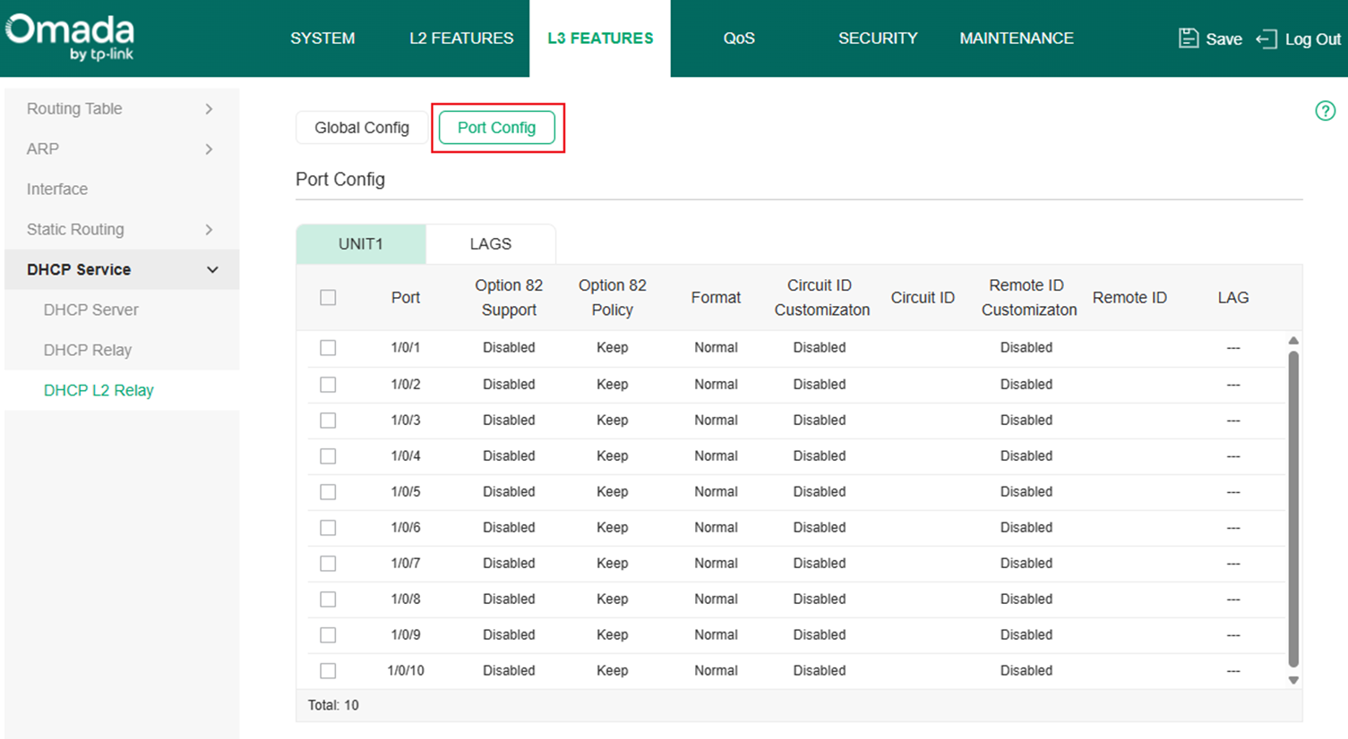
Step 5. Go to Port Config and configure related Option82 settings as you need.
Configuration in Controller Mode
Step 1. Create VLAN for DHCP Client and Server, as an example, create VLAN 2 for client and set the ports 1-2 connecting to clients as access ports of VLAN 2. Go to Network Config > Network Settings > LAN.

In VLAN section, click Add button to create a new VLAN.

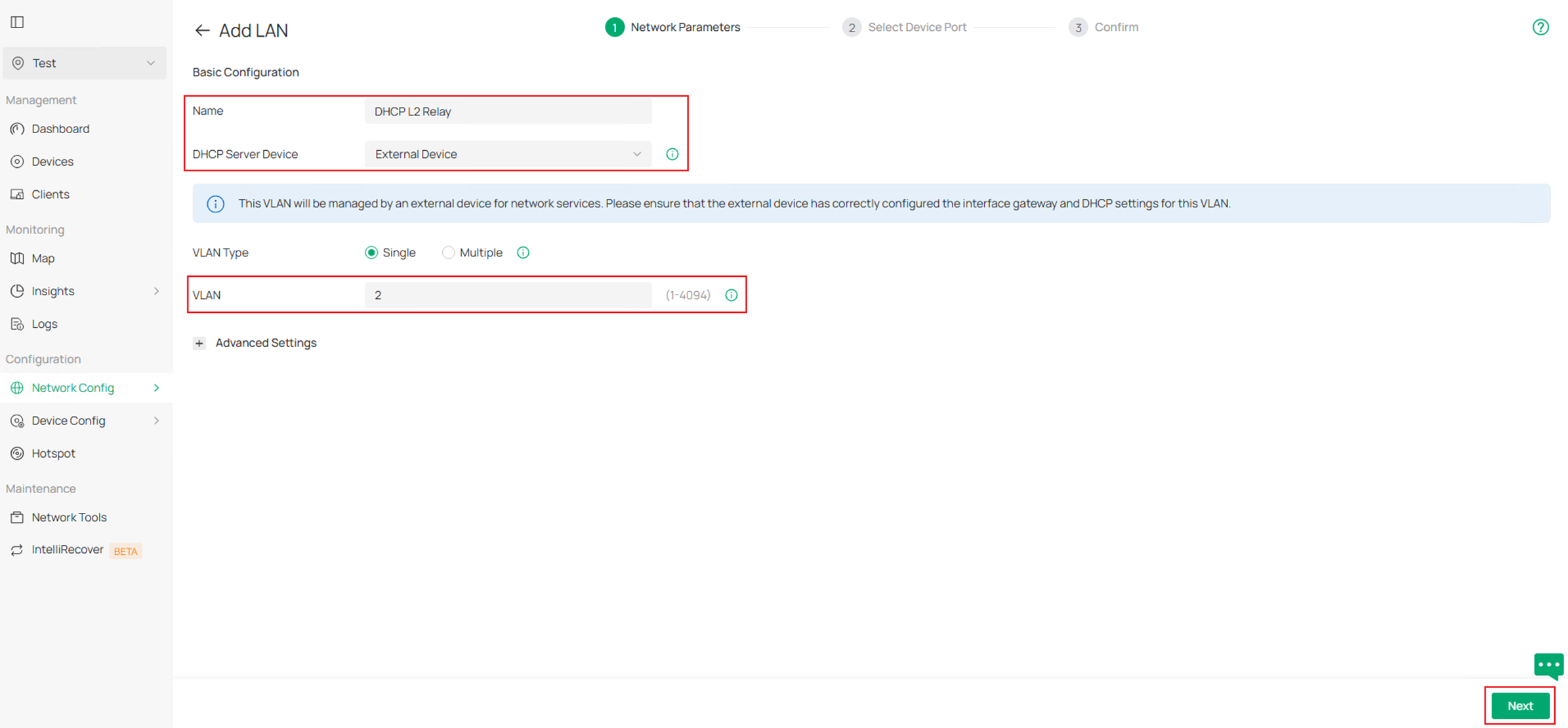
Enter the Name, choose the corresponding DHCP Server Device, in this example, we are using an third-party device as DHCP server, choose External Device as DHCP Server Device, then enter the VLAN ID. Click Next to proceed.
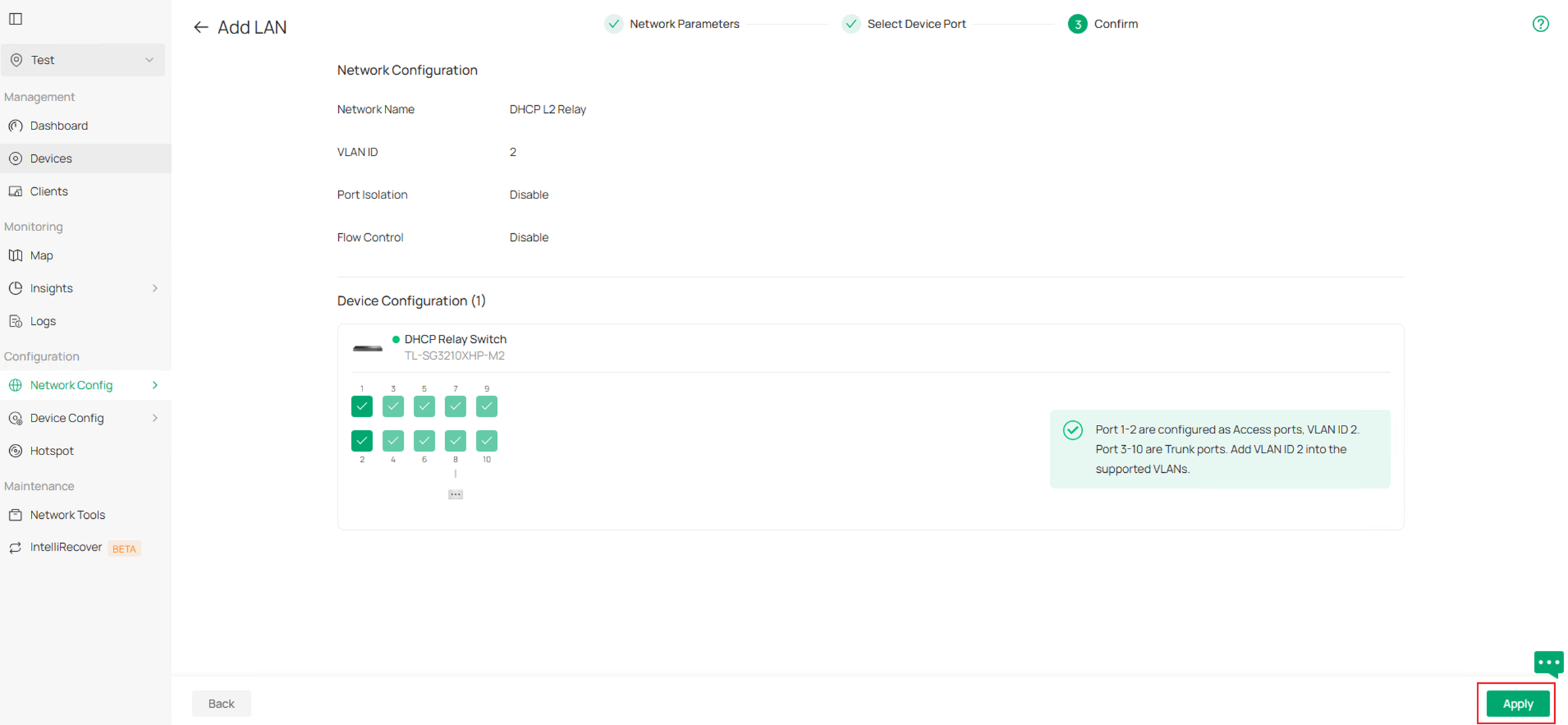
In Select Device Port page, choose the switch and select port 1-2 in this example to quickly configure them as access ports of this VLAN. Click Next to proceed.

Finally, confirm the VLAN info and click Apply to finish creating the VLAN.
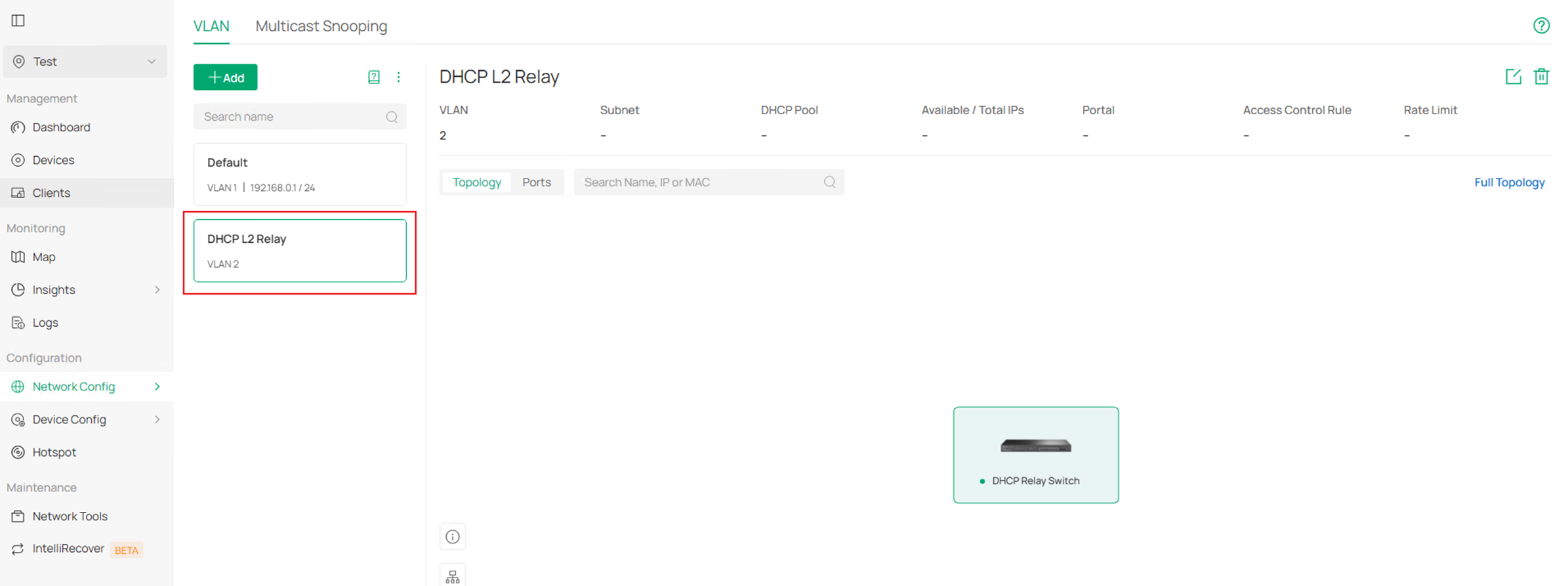
The final result should be like this:
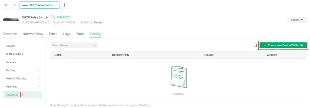
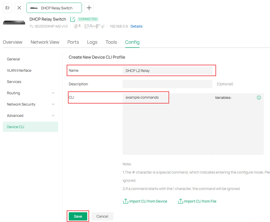
Step 2. The DHCP L2 Relay part needs to be deployed via CLI Template, go to Device CLI in Config. Click Create New Device CLI Profile.
Name this template and enter the commands, Click Save to proceed. For DHCP L2 Relay related commands, please refer to the CLI Refrence Guide in Support page of each product.
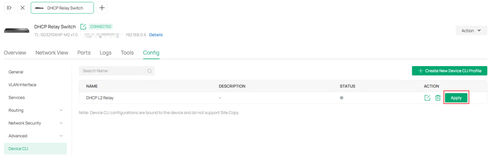
Step 3. Click Apply to push this CLI template command to device.
Here, we have finished configuring DHCP L2 Relay in Controller Mode.
Conclusion
In this article, the configuration of DHCP Interface Relay, DHCP VLAN Relay and DHCP L2 Relay under standalone mode and controller mode were introduced with a simple example.
Get to know more details of each function and configuration please go to Download Center to download the manual of your product.
