


Contents
外部DHCPサーバーを使用する構成またはDHCPサーバーを使用しない構成
はじめに
Omada Controller v5からOmada Network v6にかけて、LAN設定に関して大きな変更が行われたことを認識しています。この記事では、最新のOmada Network v6でVLAN機能を設定する方法をご紹介します。これにより、Omada Network v6でVLANを設定するワークフローをより深く理解していただけます。
要件
- Omada コントローラー
- Omada ゲートウェイ/スイッチ(オプション)
設定
デバイスをDHCPサーバーとして使用する設定
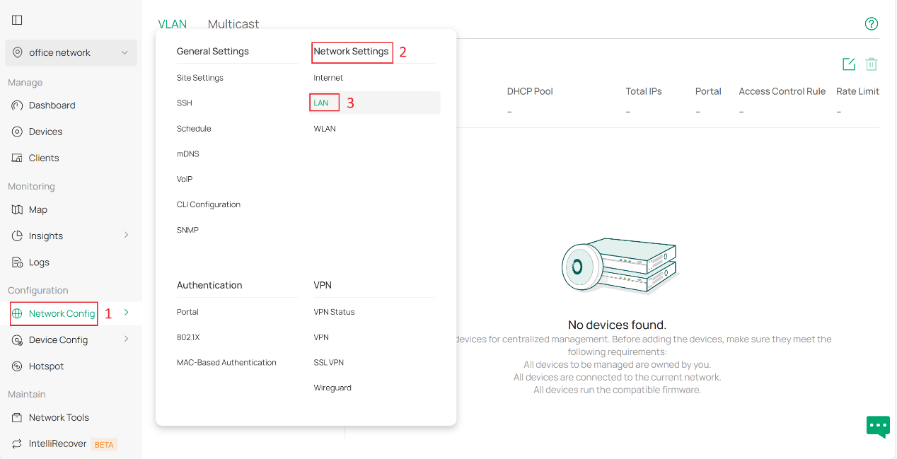
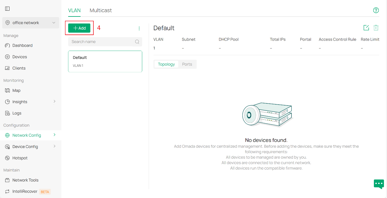
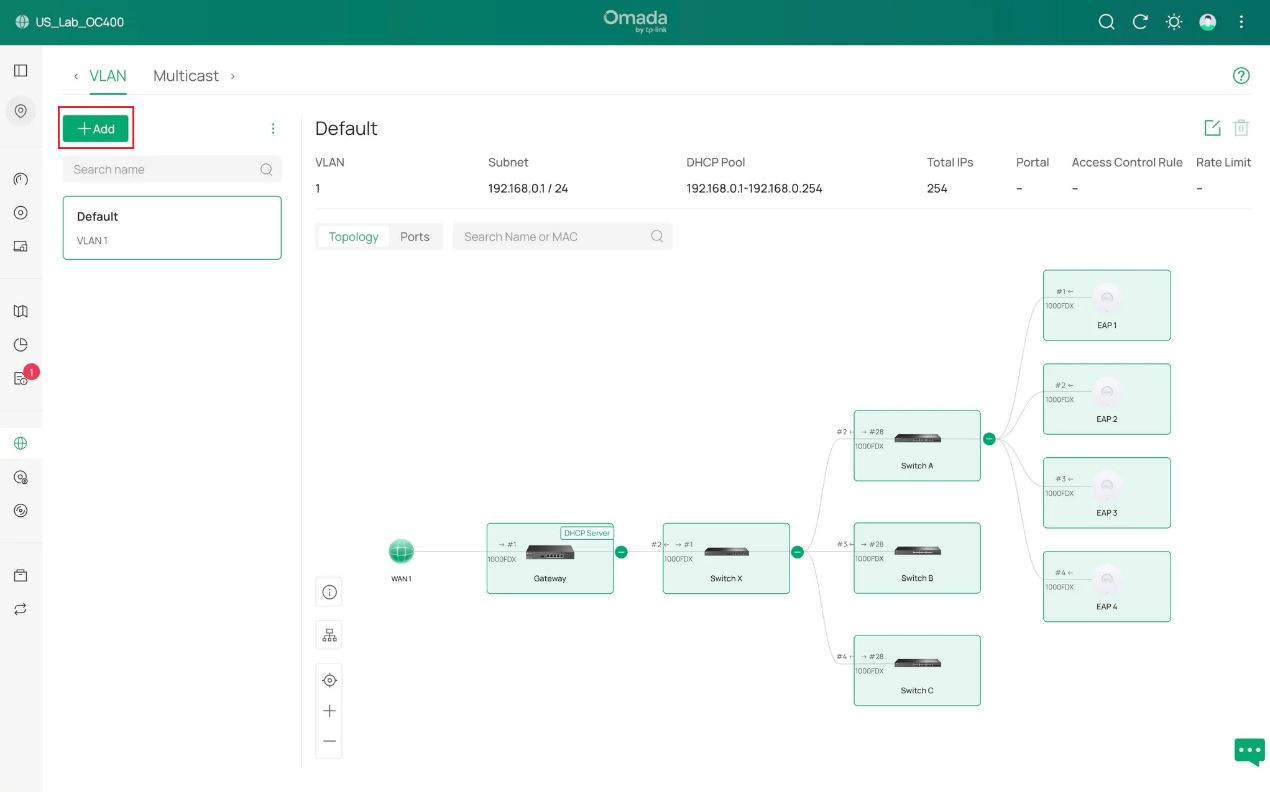
ステップ1.コントローラに新しいVLANを作成します。コントローラにログイン後、 「ネットワーク設定」>「ネットワーク設定」>「LAN」に移動し、「VLAN」列の「追加」をクリックします。
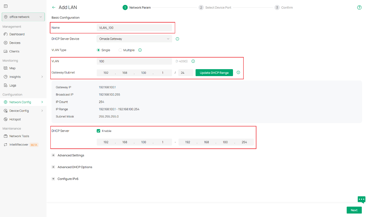
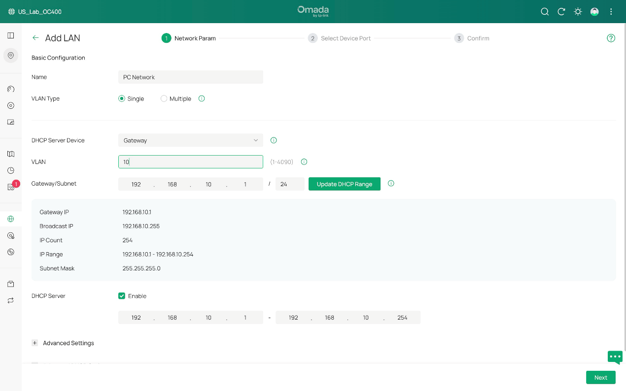
次に、基本設定から始めます。
DHCPサーバーデバイスとして、DHCPサーバーを設定するデバイスを選択します。DHCPサービスをサポートするゲートウェイまたはスイッチが対象となります。
新しいネットワークの名前、VLAN ID、サブネットを指定します。静的IPアドレスでネットワークを維持する場合は、DHCP機能を無効にできます。
OmadaスイッチをDHCPサーバーとして使用する場合は、必要に応じてこれらのパラメータを手動で設定する必要があります。IPアドレスモードは「固定」を選択し、IPアドレスとサブネットマスクを指定します。DHCPモードは「DHCPサーバー」を選択し、 DHCP範囲やDNSサーバーなどの必要なパラメータを入力します。
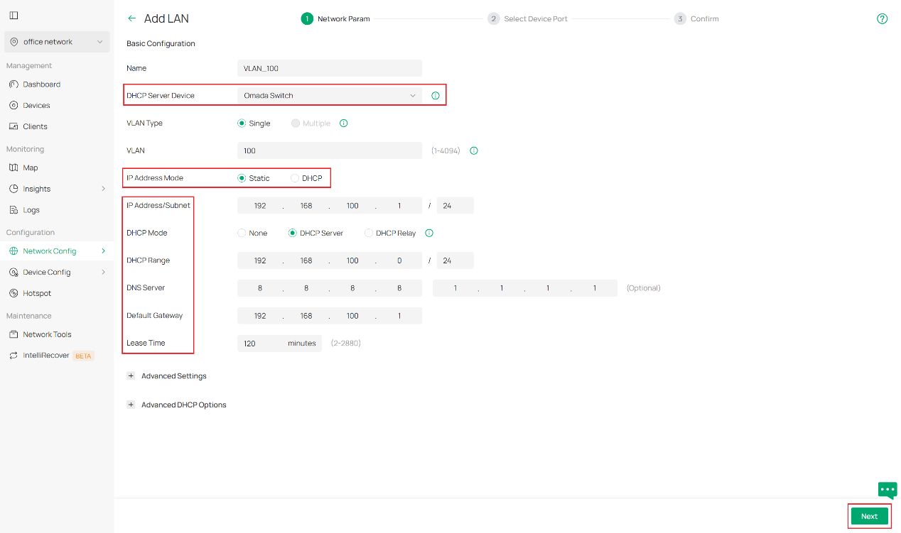
また、[詳細設定] でスヌーピング、正規の DHCP サーバー、DHCP L2 リレーなどの詳細なネットワーク設定を構成したり、[詳細 DHCP オプション] で独自のニーズに応じて DHCP オプション 138 およびカスタム DHCP オプションを構成したりすることもできます。さらに質問がある場合は、これらの機能の詳細については、他の FAQ を参照してください。
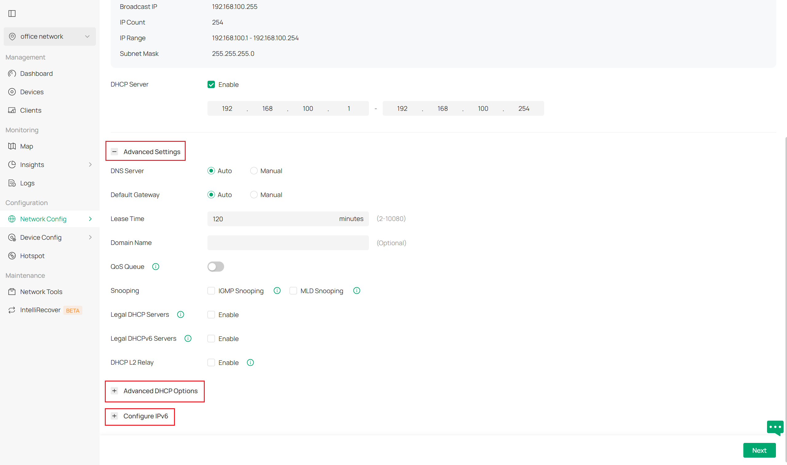
必要な設定をすべて完了したら、「次へ」をクリックして続行します。
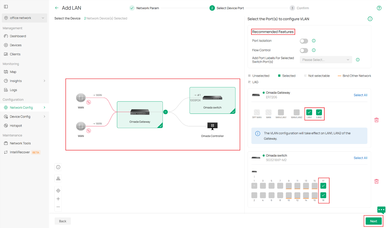
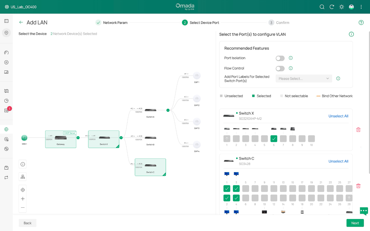
ステップ 2. デバイスポートを選択します。次のページでは、デバイスのポートを選択します。これを行うには、最初に設定するデバイスをクリックし、次にこの VLAN 設定セットが適用されるポートを選択します。スイッチ ポートの場合、どの VLAN 設定でもポートが選択されていない場合、そのポートは接続を維持するためにすべての VLAN を所有するトランク ポートになることに注意してください。これらのアクセス ポートで、ポート分離やフロー制御などの推奨機能を有効にすることもできます。次に、「次へ」をクリックして続行します。
注:この手順では、ネットワークのスイッチのアクセスポート(ホストまたはクライアント(例:PC)に接続するポート)を選択することをお勧めします。ゲートウェイについては、ブランチで必要な場合は有効化する必要があります。設定結果は手順3で示され、動作が説明されています。.
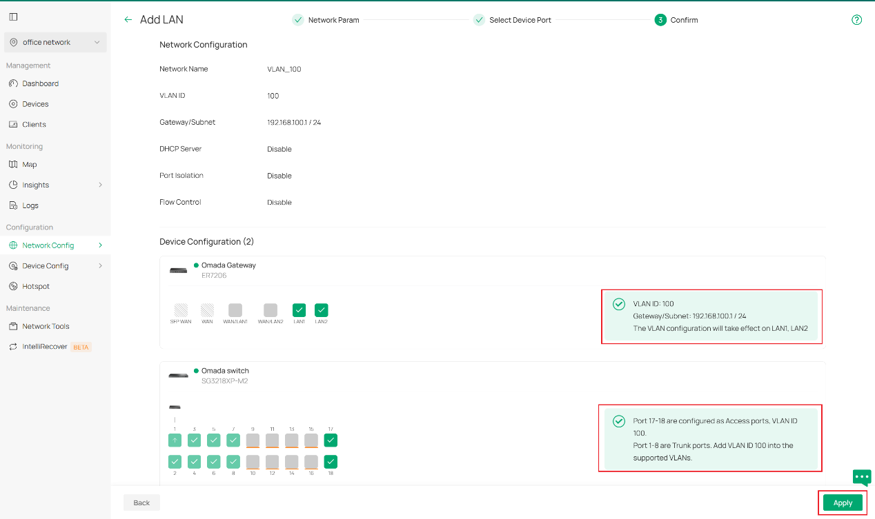
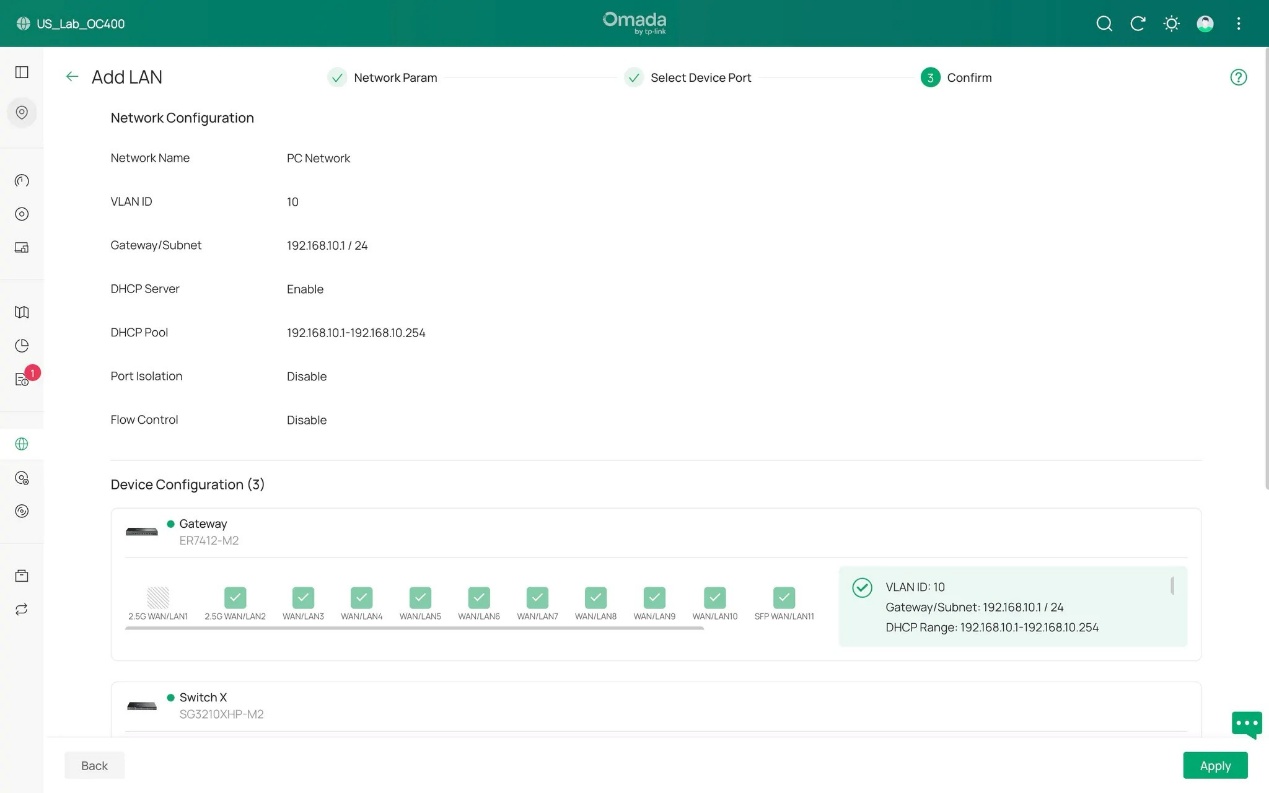
ステップ3. 設定内容を確認します。期待どおりに表示されている場合は、「適用」をクリックして終了します。
このFAQの一連のスクリーンショットで示されているように、ポートLAN1とLAN2にVLAN 100が設定され、DHCPサーバーが接続されているゲートウェイと、ポート17と18をVLAN 100のアクセスポート、ポート1~8をVLAN 100と事前に設定した他のVLANを含む複数のVLANを収容するトランクポートとして設定したスイッチを使用します。(ポート9~16には既に他のVLANが設定されており、そのVLANのアクセスポートとして事前に設定されています。)
Note: To further configure the switch port's network settings, like PVID, tag/untag etc., please go to the switch details page and edit the port if more configuration actions are needed.
Configuration with an external DHCP server or without DHCP server
Sometimes you may not be willing to set a DHCP server on Omada devices but want to add an existing VLAN, which may have been already well configured on routers or firewalls from other vendors to your downstream Omada devices, like EAPs or access switches. Or what you want is simply a pure layer 2 network with static IP addresses.
For these scenarios, what differs from the previous stage is that you need to select External Devices or None when selecting DHCP server Device.
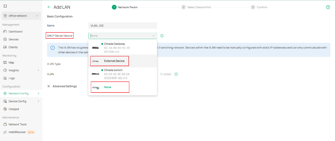
The rest of the remaining part is basically the same workflow as the first stage.
Verification
In this chapter we demonstrate an example stage of network office configuration to illustrate how VLAN is set with Omada Controller 6.0. Network design as picture shown below.
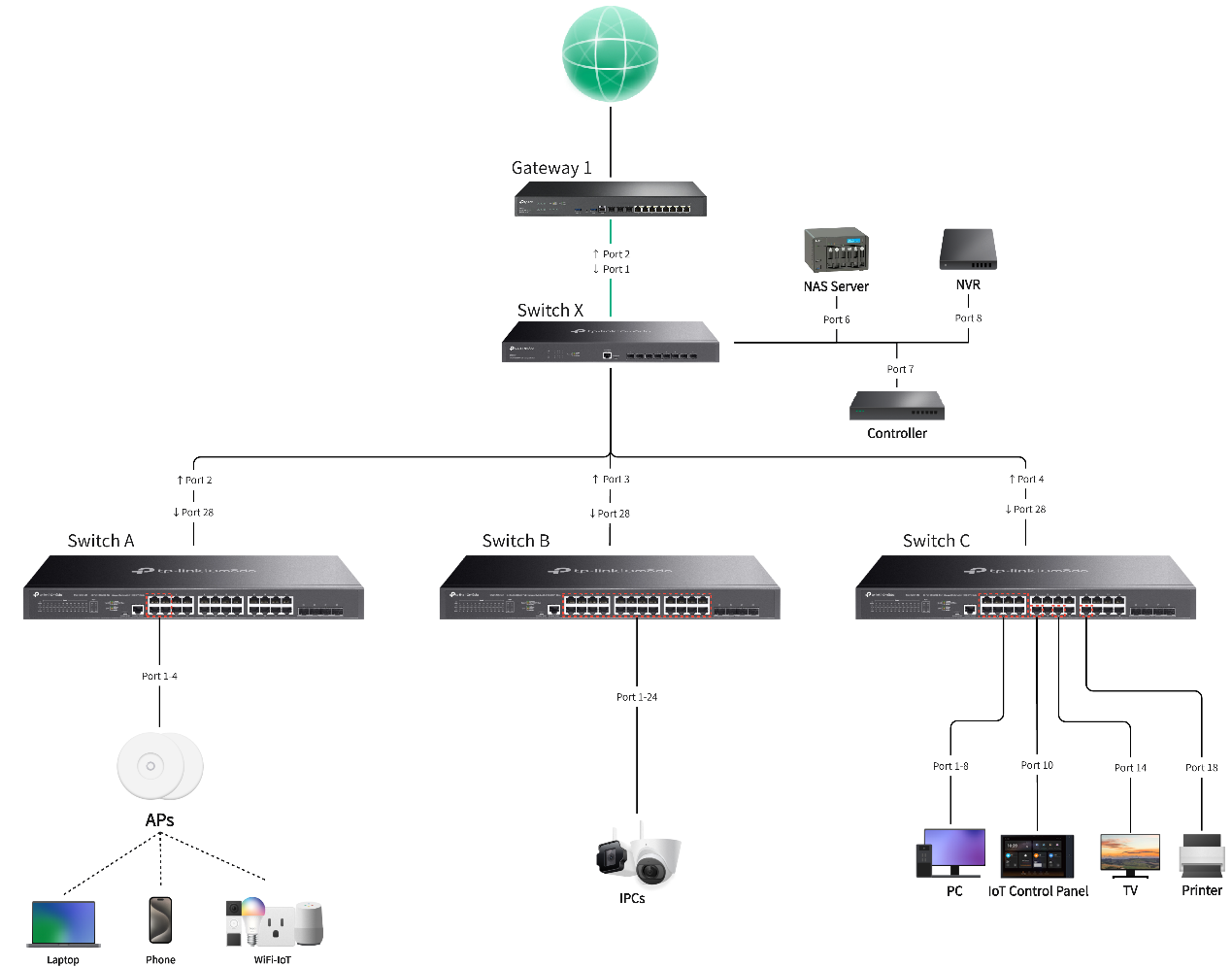
For VLAN regulation of this instance, we plan to use VLAN 1 for network device management, VLAN 10 for employee PCs, VLAN 20 for guest access, VLAN 30 for security devices inside the office and VLAN 40 for IoT equipment. Their IP range and port planning as detailed with the following charts.
|
Network Name |
Usage |
VLAN ID |
Gateway/IP Range |
Ports |
SSID |
|
Default |
Default management network for network infrastructure devices and system administration |
1 |
192.168.0.1/24 |
SW A port 1-4 |
/ |
|
PC Network |
Primary employee network for desktop computers and workstations |
10 |
192.168.10.1/24 |
SW C port 1-4 |
/ |
|
Guest Network |
Isolated network for guest users with limited internet access only |
20 |
192.168.20.1/24 |
/ |
Guest SSID |
|
Security Network |
Dedicated network for security cameras, access control systems and surveillance equipment |
30 |
192.168.30.1/24 |
SW B port 1-24 |
/ |
|
IoT Network |
Segregated network for smart devices, sensors, and IoT equipment with controlled access |
40 |
192.168.40.1/24 |
SW C port 10,14,18 |
IoT SSID |
Here we take the configuration of VLAN 10 as an example, the configuration method for other VLANs is similar to this one. After we connect all devices in order, we start with creation of VLAN 10 since VLAN 1 is generated by default. Click add on the top left to enter the edit page.
We create VLAN 10, select Omada gateway as DHCP server with DHCP service enabled and name it PC Network.
Then we select the ports which are expected to be the access ports of PC Network, 4 PCs and 1 NAS included. We grant them access to VLAN 10. This can be achieved by either ticking the ports one by one or dragging a blank covering multiple ports. Red garbage can icon is used for clearing all ports that are selected. Don’t worry about uplink ports, they will be containing VLAN 10 after configuration is completed as long as they remain as trunk ports.
After that, we push forward to the confirmation page. It behaves as we expected, so we click Apply to finish. And it is completed for generating a VLAN.
Now, we are going to demonstrate how to edit the existing VLAN configuration.
Given that we have 4 more new workers coming to add join, we need to add four more PCs into office network, which means, to VLAN 10.
To do this, after connecting the 4 new PCs to port 5-8 of switch C, we go to Network Config > LAN, find PC Network(VLAN 10) on the left side and click edit button on the right side. In the following page you may edit network parameters for this VLAN. Yet it is not needed in the example scenario, we will simply skip it to the next page where access ports will be defined.
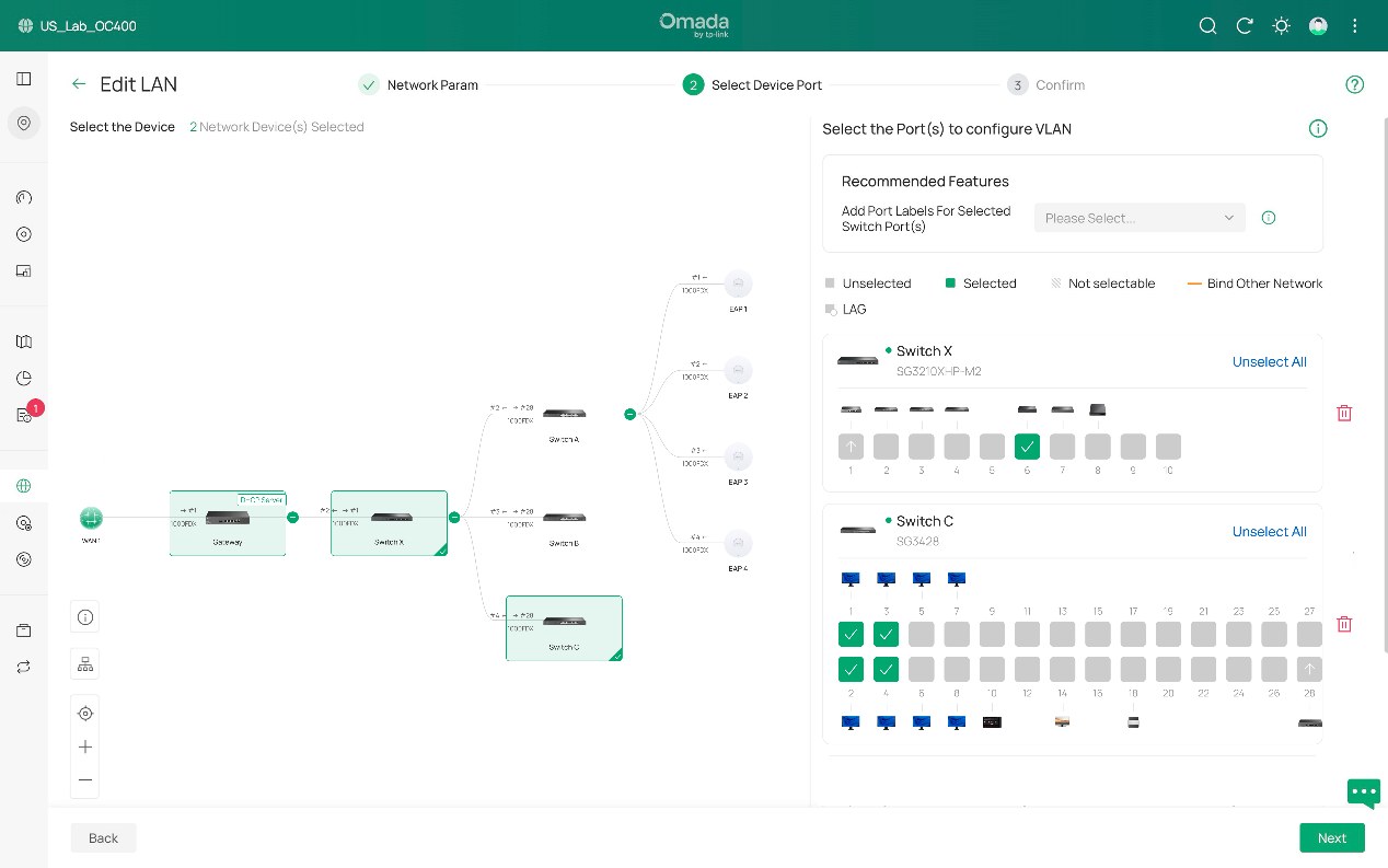
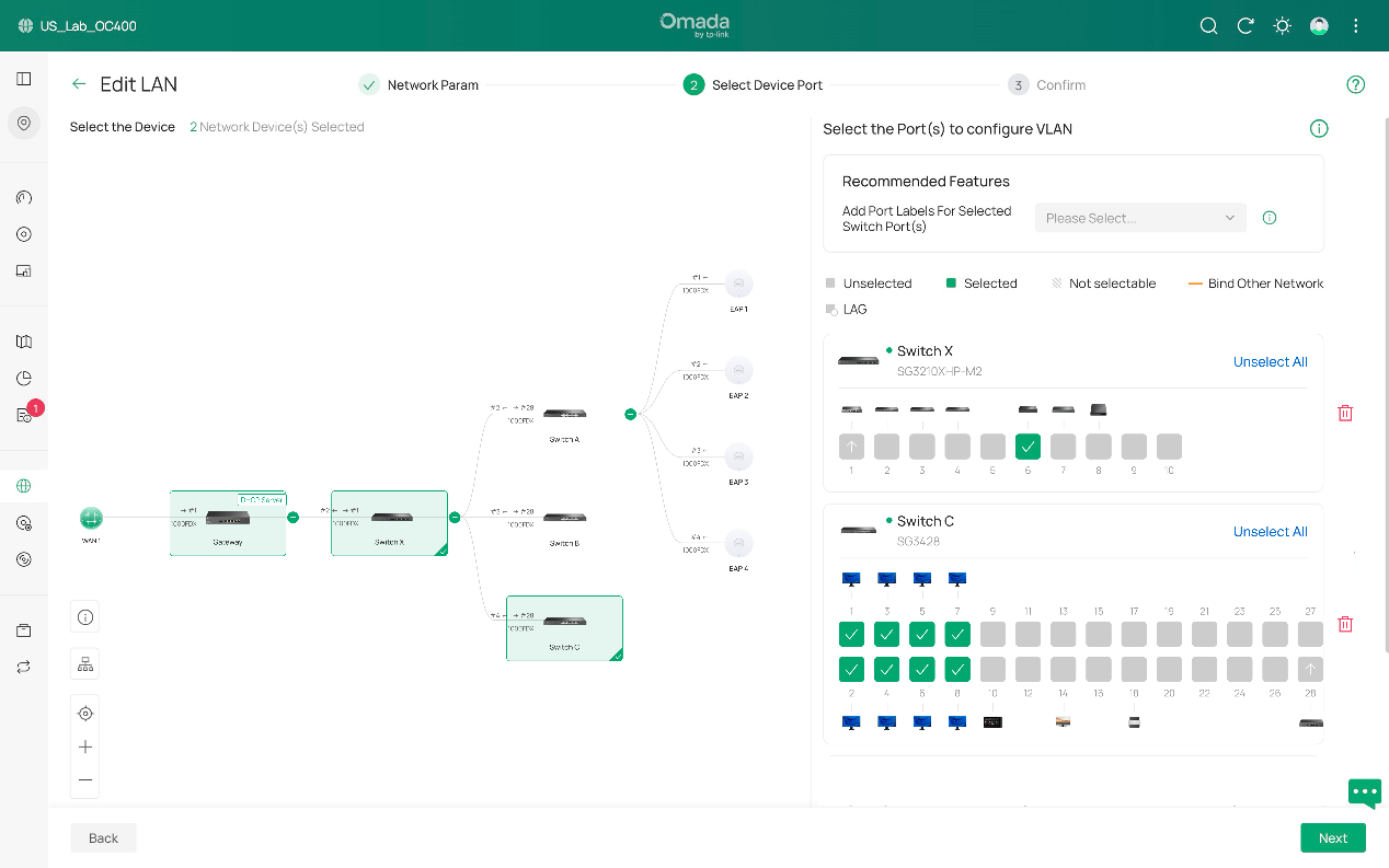
As we click switch C to open its port details, you can see that it is shown here that we have detected 4 new PCs with port 5-8. Now with similar move we select port 5-8 and make them access ports of VLAN 10 as well.
Lastly, it’s confirmation phase for checking the status of VLAN 10. If it behaves as what you want, click Apply and the edit is then completed.
Conclusion
These are steps of how to create VLAN with the newest Omada Controller v6. Simply speaking, it follows a sequence of configurating parameters, selecting ports, confirmation and repeat for a different VLAN. Editing existing VLAN follows this order as well.
For veterans to quickly get what has been changed, as you may have already discovered, a major difference is that VLAN configurations now are independent and no longer related to switch profile.
Our old pattern works like “Network > Port Profile > Switch Port”, VLAN in switch port cannot be directly modified, you have to change the contents in Port Profile to realize the modifications to VLAN in switch port. And for now, it works like “Network > Switch Port”, we firstly configure VLAN for overall network, if further adjustments are needed, then we move directly to switch port/ports (drag your mouse to select multiple units) in device details page and directly modify tag, PVID, etc. specification for advanced configurations.
Get to know more details of each function and configuration please go to Download Center to download the manual of your product.
