


Configuration for Standalone Mode
Configuration for Controller Mode
Introduction
When hosting an internal server behind an Omada Gateway, such as a web server, exposing it to the Internet can pose security risks. This guide demonstrates how to allow only specific public IP addresses to access an internal server, while blocking all other public traffic.
Requirements
- Omada Gateway
Network Topology
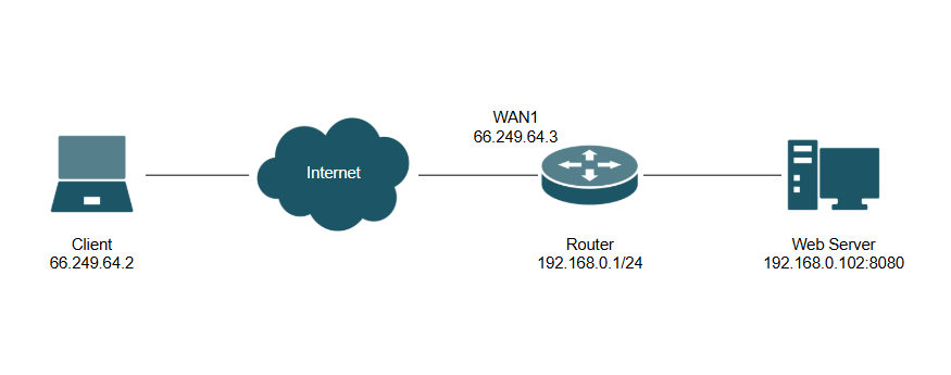
Note: For this guide, an ER605, OC200 hardware controller, and Linux-based internal Web Server running on port 8080 were used. Follow the same steps for a software and cloud controller.
Configuration
Configuration for Standalone Mode
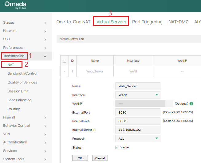
Step 1. Go to Transmission > NAT > Virtual Servers to map the internal server port to the WAN interface. In this example, there is an internal web server on 192.168.0.102:8080.
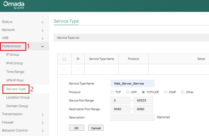
Step 2. Go to Preferences > Service Type and create a custom service type defining the specific protocol and port used by the internal server. Select Source Port Range to be 0-65535 and set the Destination Port Range to the port used by the internal server, which is 8080 in this example.
Step 3. Go to Preferences > IP Group > IP Address to define the target IP addresses. Create two IP addresses: one for the allowed client’s external IP (Allowed_Client) and one for the internal server’s local IP (Internal_Server).
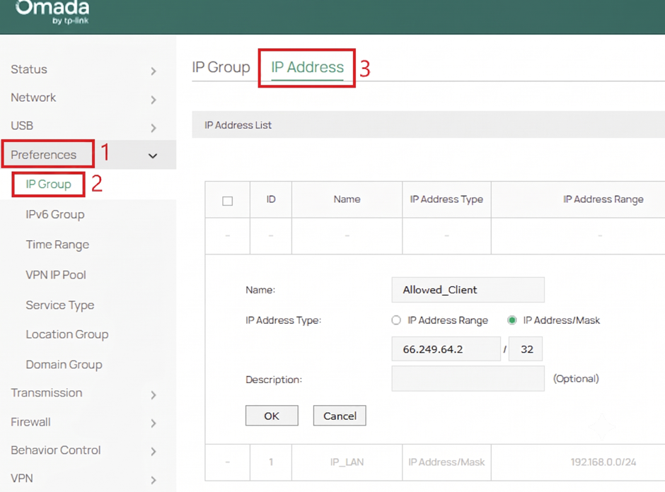
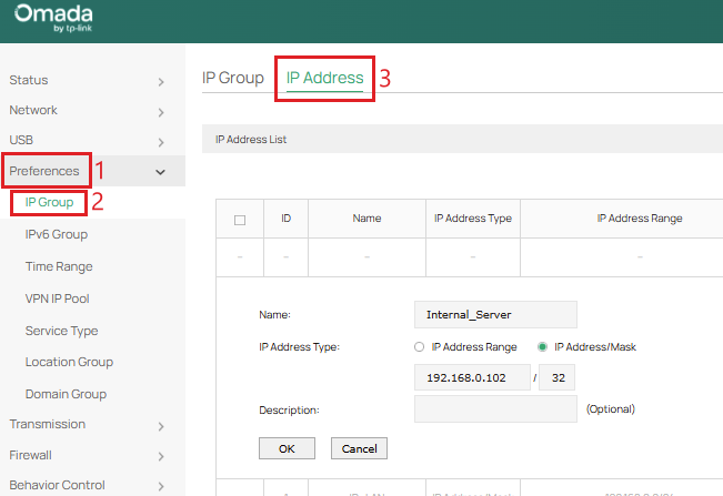
Note: Ensure the IP address of the external client and internal server are either set statically or have a DHCP reservation so the IP address does not change.
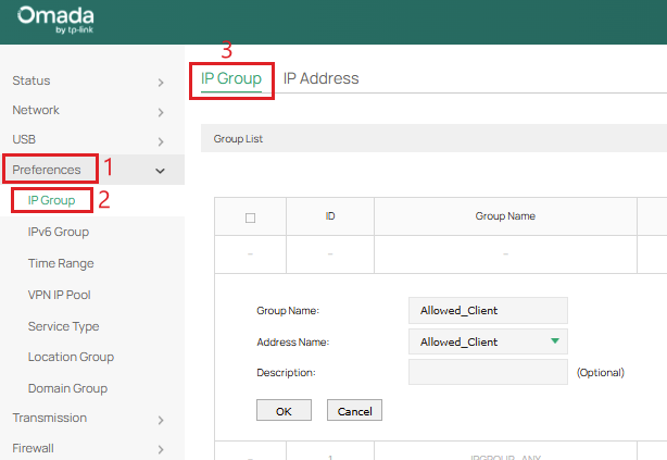
Step 4. Go to Preferences > IP Group > IP Group to create two IP groups for each respective IP address that was created.

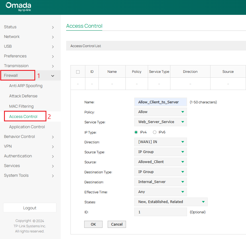
Step 5. Go to Firewall > Access Control to create two firewall policies. First, create an Allow rule mapping the source “Allowed_Client” IP Group to the destination “Internal_Server” IP Group using the Service Type created on the respective “WAN IN” interface with an ID of 1.
Next, create a Block rule mapping source “IPGROUP_ANY” IP Group to destination “Internal_Server” IP group using the Service Type created on the respective “WAN IN” interface with an ID of 2.
Note: In Controller Mode, “Service Type” has been replaced with “Protocols.”
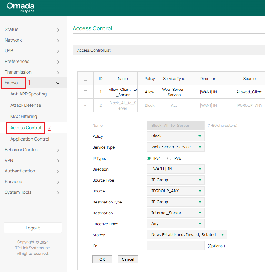
Note: ACL rules are processed sequentially, from the lowest ID number to the highest ID number. This is why the Allow rule needs to go before the Block rule.
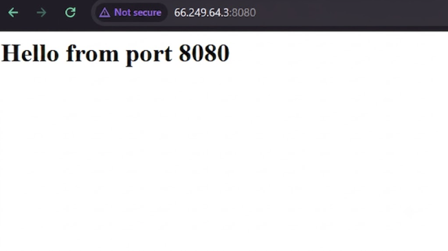
Step 6. Verify only the external client (66.249.64.2) can access the internal server (192.168.0.102:8080) by accessing the WAN port IP address with the correct port of the internal server (66.249.64.3:8080)
When external client is changed to a different IP address (66.249.64.4), they can no longer access the internal server due to the ACL rule only allowing 66.249.64.2:

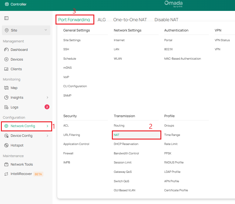
Configuration for Controller Mode
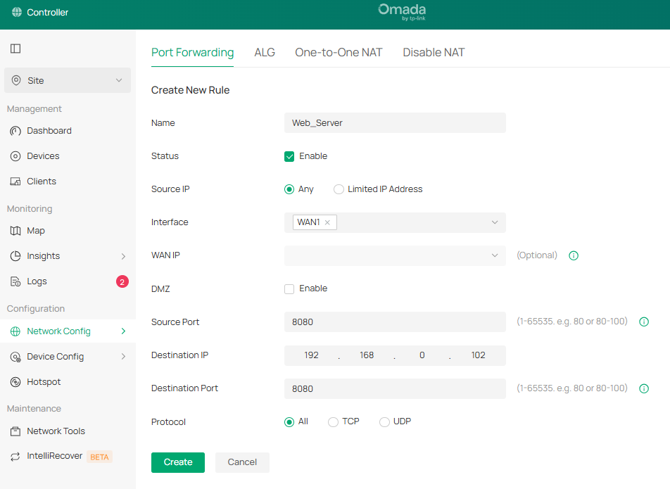
Step 1. Go to Network Config > Transmission > NAT > Port Forwarding to map the internal server port to the WAN interface. In this example, there is an internal web server on 192.168.0.102:8080.
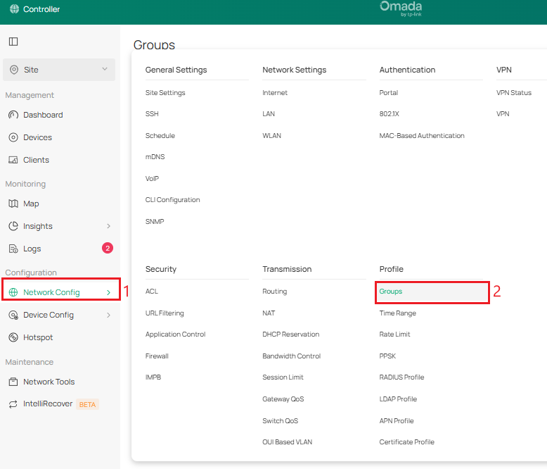
Step 2. Go to Network Config > Groups to create an IP Group for the external client (66.249.64.2) and an IP-Port Group for the internal web server (192.168.0.102:8080).
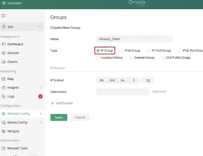
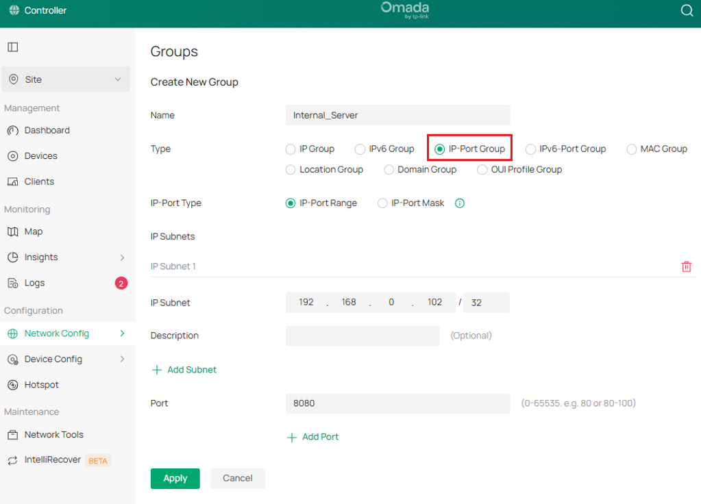
Note: Ensure the IP address of the external client and internal server are either set statically or have a DHCP reservation so the IP address does not change.
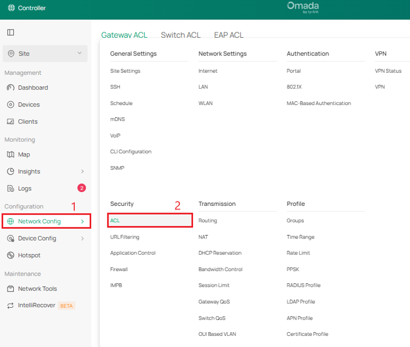
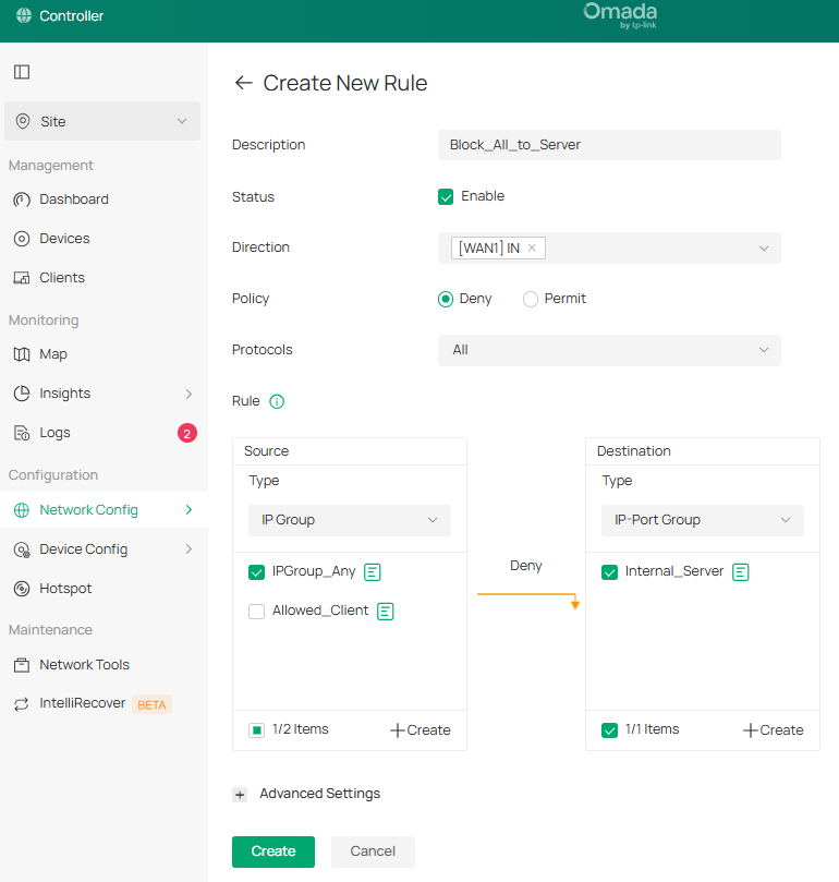
Step 3. Go to Network Config > ACL > Gateway ACL to create two firewall policies.
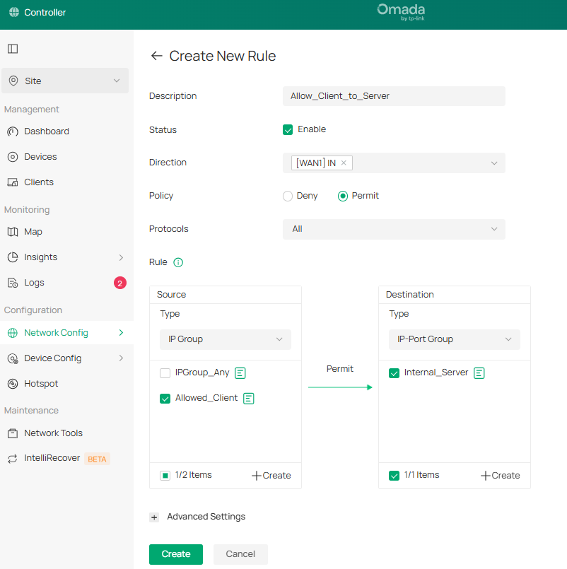
First, create a Permit rule mapping the source “Allowed_Client” IP Group to the destination “Internal_Server” IP-Port Group on the respective “WAN IN” interface for “All” Protocols.
Next, create a Deny rule mapping source “IPGROUP_ANY” IP Group to destination “Internal_Server” IP-Port Group on the respective “WAN IN” interface. “All” Protocols is selected for complete isolation.
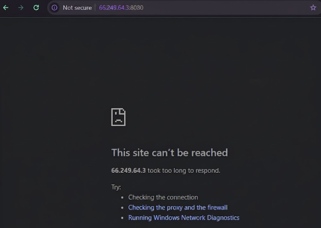
Step 4. Verify only the external client (66.249.64.2) can access the internal server (192.168.0.102:8080) by accessing the WAN port IP address with the correct port of the internal server (66.249.64.3:8080)

When external client is changed to a different IP address (66.249.64.4), they can no longer access the internal server due to the ACL rule only allowing external client 66.249.64.2:
Conclusion
We have successfully allowed a specific public IP address to access an internal server.
QA
Q1: What if I use IP-Group instead of IP-Port Group in Controller Mode?
A1: If a standard IP Group is used, the ACL rule will target all ports on that host instead of isolating the port used for the internal server.
Q2: What if the external client suddenly loses access to the internal server?
A2: Check if the external client’s public IP address has changed or if it is set dynamically. The IP address needs to match the same one that was set as the IP profile.
Get to know more details of each function and configuration please go to Support Home to download the manual of your product.
