


How to Configure Access Control on Omada Gateway in Standalone Mode and Controller Mode


Contents
Scenario I: Network Isolation (Bi-Directional)
Scenario II: Management VLAN Access (Uni-Directional)
Scenario III: Restrict VPN User Access to Specific Local Resources
Scenario IV: Internet Access Only
Introduction
Access Control Lists (ACLs) control traffic between networks, devices, and services by permitting or denying it based on defined criteria. ACLs can be used to enhance network security, enforce access policies, and isolate resources within the network.
This guide demonstrates several common ACL deployment scenarios on Omada Gateways in both Controller Mode and Standalone Mode. These examples include network isolation, management network protection, VPN access restrictions, and Internet-only access policies. By following these scenarios, administrators can better understand how ACLs can be used to secure and manage traffic within their network environment.
Requirements
- Omada Gateway
- Omada Controller
Parameters Reference
Gateway ACL in Controller Mode:
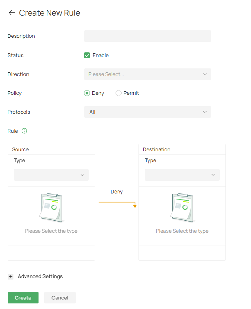
Description: Enter a description to identify the ACL.
Status: Click the checkbox to enable the ACL.
Direction: Select the traffic flow to which the ACL rule will be applied.
Policy: Select the action to be taken when a packet matches the rule.
Deny: Discard the matched packet.
Permit: Forward the matched packet.
Protocols: Select one or more protocol types to which the rule applies from the drop-down list. The default is All, indicating that packets of all protocols will be matched. With one of TCP, UDP or both are selected, you can set the IP address and port number of a packet as packet-filtering criteria in the rule.
Log: When enabled, the system can collect ACL entry effective log. To use this function, please configure the remote logging function first.
Rule:
1) Source: Select the source criteria from the drop-down list to compare against a packet.
Network: Select the network you have created. If no networks have been created, you can select the default network (LAN), or go to Network Config > Network Settings > LAN to create one.
! Network: Select a network you have created and the settings will not be applied to that network.
IP Group: Select the IP Group you have created. If no IP Groups have been created, click + Create on this page or go to Network Config > Profile > Groups to create one. The system will examine whether the source IP address of the packet is in the IP Group.
! IP Group: Select an IP Group you have created and the settings will not be applied to that IP Group.
2) Destination: Select the destination criteria from the drop-down list to compare against a packet.
Network: Select the network you have created. If no networks have been created, you can select the default network (LAN), or go to Network Config > Network Settings > LAN to create one.
! Network: Select a network you have created and the settings will not be applied to that network.
IP Group: Select the IP Group you have created. If no IP Groups have been created, click + Create on this page or go to Network Config > Profile > Groups to create one. The system will check whether the packet's source IP address is in the IP Group.
! IP Group: Select an IP Group you have created and the settings will not be applied to that IP Group.
Gateway Management Page: This option will allow/block all packets sent from the specified source to the gateway’s WAN and LAN interface IP.
Advanced Settings:
Time Range: Create the time range or select an existing time range for the acl rule to take effect.
Bi-Directional: In the LAN-LAN direction, click the checkbox to enable the gateway to create another symmetric ACL with the name “xxx_reverse”, where “xxx” is the name of the current ACL. The two ACLs target at packets with the opposite direction of each other.
States Type: Determine the type of stateful ACL rule. It is recommended to use the default Auto type.
Auto (Match Sate New/Established/Related): Match the new, established, and related connection states.
Manual: If selected, you can manually specify the connection states to match.
Match State New: Match the connections of the initial state. For example, a SYN packet arrives in a TCP connection, or the router only receives traffic in one direction.
Match State Established: Match the connections that have been established. In other words, the firewall has seen the bidirectional communication of this connection.
Match State Related: Match the associated sub-connections of a main connection, such as a connection to a FTP data channel.
Match State Invalid: Match the connections that do not behave as expected.
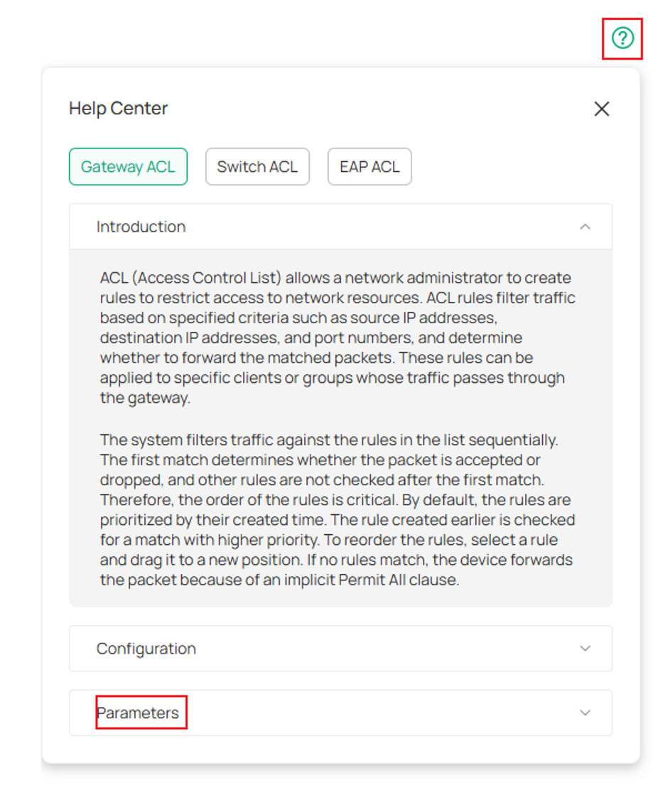
To see the definition of all the parameters, please click the help center at the top right of the ACL creation screen and expand Parameters.
Gateway ACL in Standalone Mode:
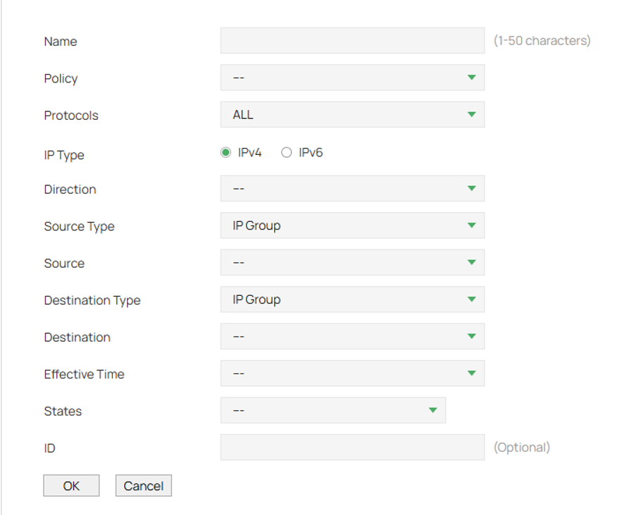
Policy: Select whether to block or allow the packets matching the rule to access the network.
IP Type: Specify the IP type to apply the rule: IPv4 or IPv6.
Direction: Select the effective traffic direction for the rule.
- ALL: Match the traffic in any direction.
- LAN->WAN: Match the traffic from LAN to WAN.
- LAN->LAN: Match the traffic from LAN to LAN.
- [WAN] IN: Match the traffic coming in via [WAN].
Source/Destination Type: Select the source/destination type of the created rule.
IP/IPv6 Group: The rule applies to specific IP/IPv6 groups. With this option selected, choose the IP/IPv6 group. If you want to create or customize IP/IPv6 groups, go to Preferences > IP Group or Preferences > IPv6 Group. The selected IP/IPv6 group contains wired and wireless clients of the corresponding IP/IPv6 addresses.
Network: The rule applies to specific LAN networks. With this option selected, choose the network. If you want to create or customize networks, go to Network > LAN. The selected LAN Network contains all clients of the wired network and the SSIDs that belong to this LAN Network.
Source/Destination:
Select IP/IPv6 Group: From the drop-down list, select an IP/IPv6 group to specify the source/destination address range for the rule. The IP/IPv6 group referenced here can be created at Preferences > IP Group or Preferences > IPv6 Group.
Select Network: From the drop-down list, select a LAN Network to specify the source/destination LAN Network range for the rule. The LAN Network referenced here can be created at Network > LAN.
Effective Time: Select the effective time for the rule. The effective time referenced here can be created on the Preferences > Time Range page.
States: Determine the type of stateful ACL rule. It is recommended to use the default Auto type.
New: Match the connections of the initial state. For example, a SYN packet arrives in a TCP connection, or the router only receives traffic in one direction.
Established: Match the connections that have been established. In other words, the firewall has seen the bidirectional communication of this connection.
Related: Match the associated sub-connections of a main connection, such as a connection to a FTP data channel.
Invalid: Match the connections that do not behave as expected.
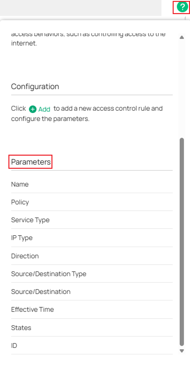
To see definition of all the parameters press ? at the top right of the page and see Parameters.
Scenario I: Network Isolation (Bi-Directional)
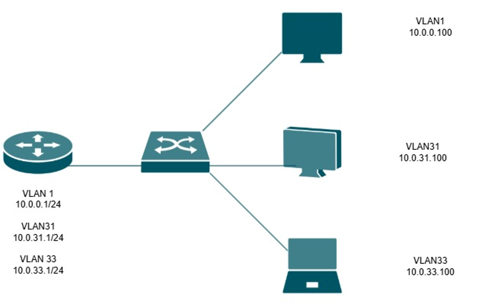
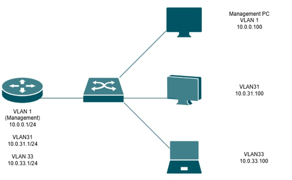
In this example, VLAN 31 (10.0.31.0/24) and VLAN 33 (10.0.33.0/24) will be isolated from one another using LAN-to-LAN ACL rules. Devices within these networks will be unable to communicate across VLAN boundaries, while traffic to other internal networks and the Internet will remain unaffected.
Since Omada Gateway ACLs include an implicit permit rule, only traffic matching the configured deny rules will be blocked. All other traffic will continue to be forwarded normally.
Controller Mode
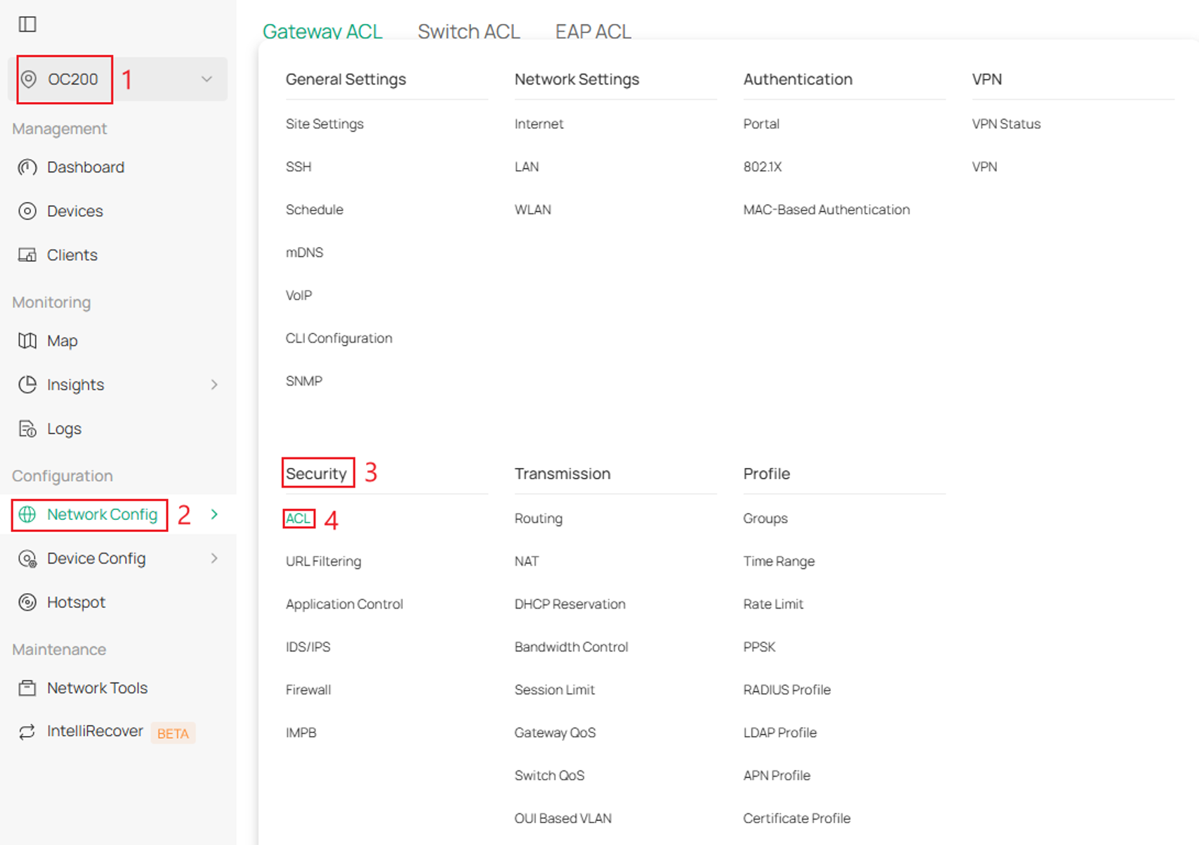
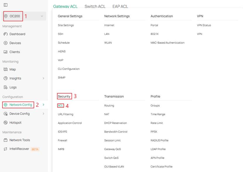
Step 1. Log into the controller and navigate to your Site > Network Config > Security > ACL.

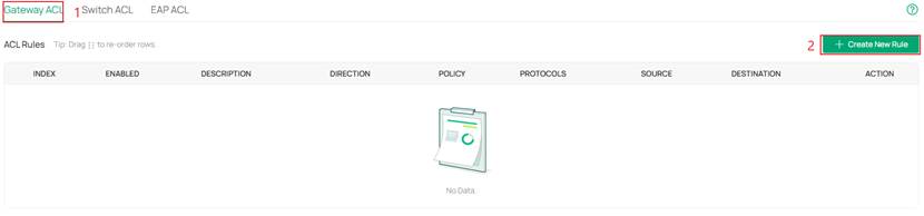
Step 2. Next, go to Gateway ACL and click Create New Rule.

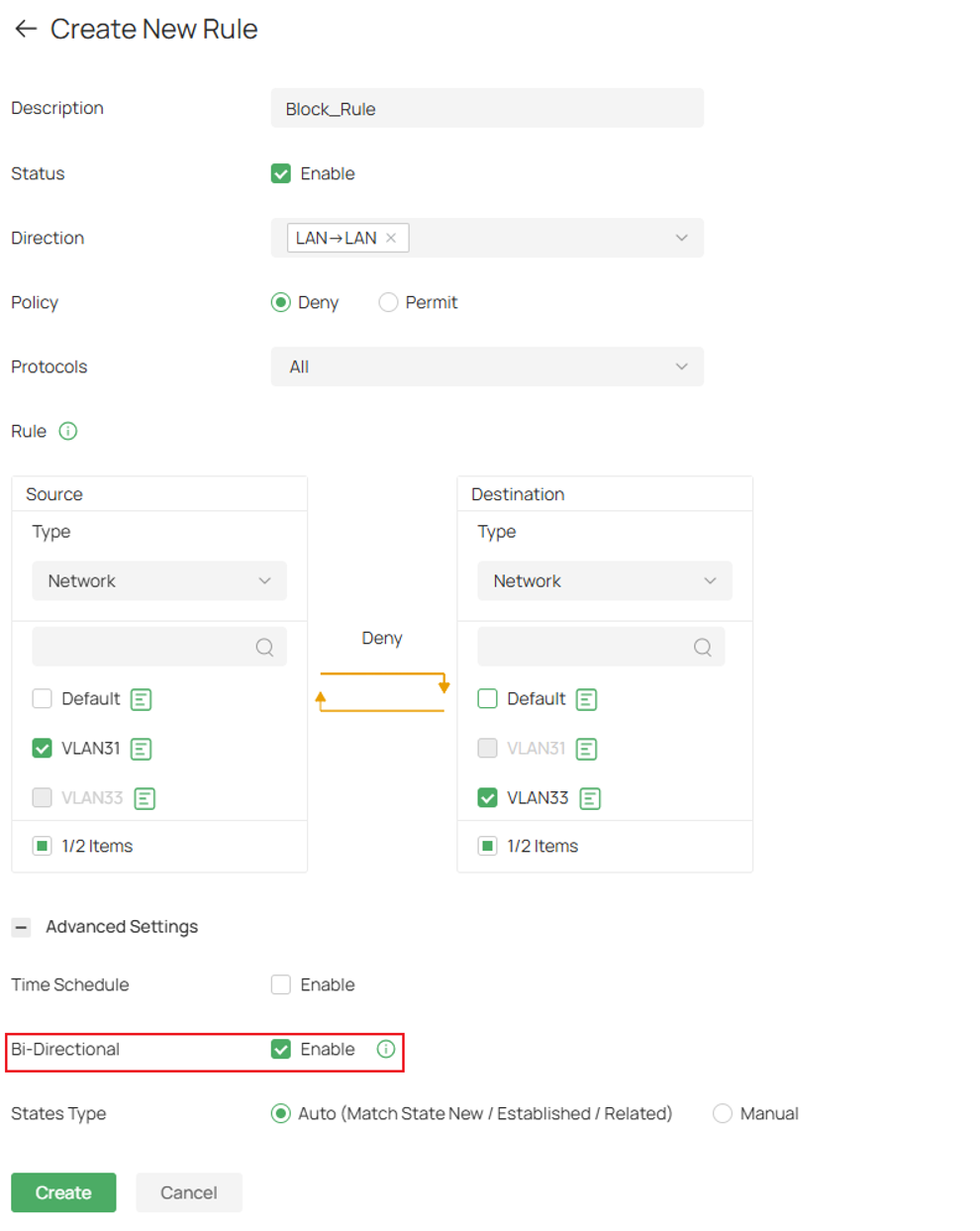
Step 3. Here, a rule is created to deny VLAN 31 to VLAN 33.
Fill in the appropriate parameters
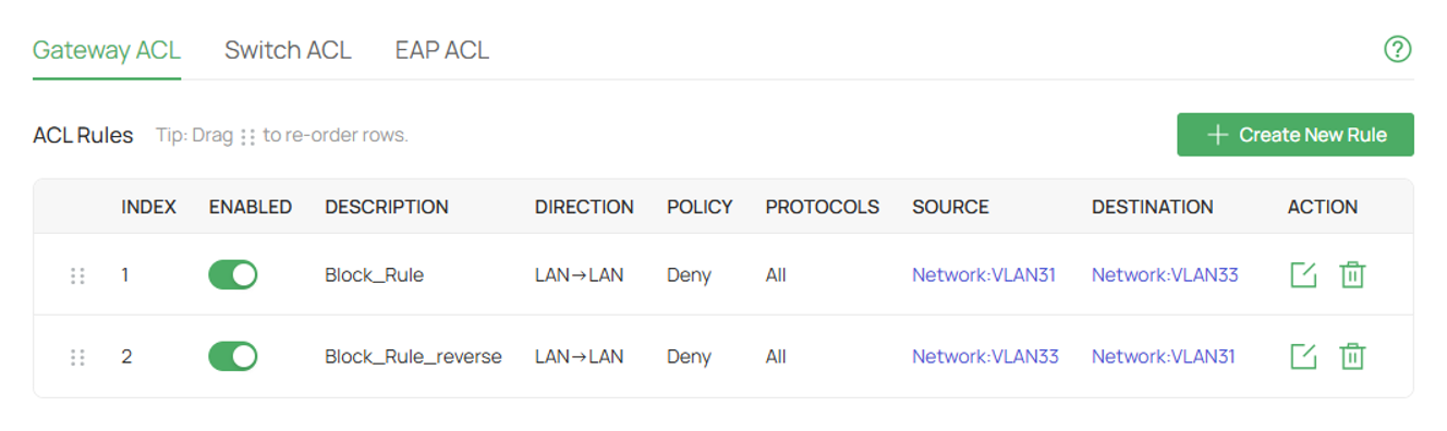
Click Advanced Settings and select Bi-Directional to automatically create another rule that swaps Source and Destination
Select Create once complete
Standalone Mode
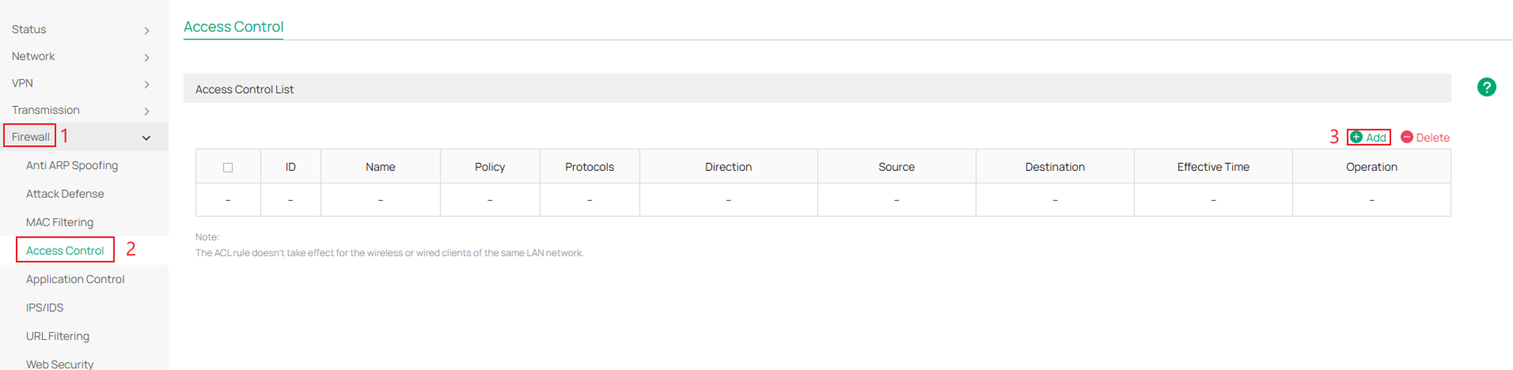
Step 1. Log in to your router, navigate to Firewall > Access Control, and click Add.
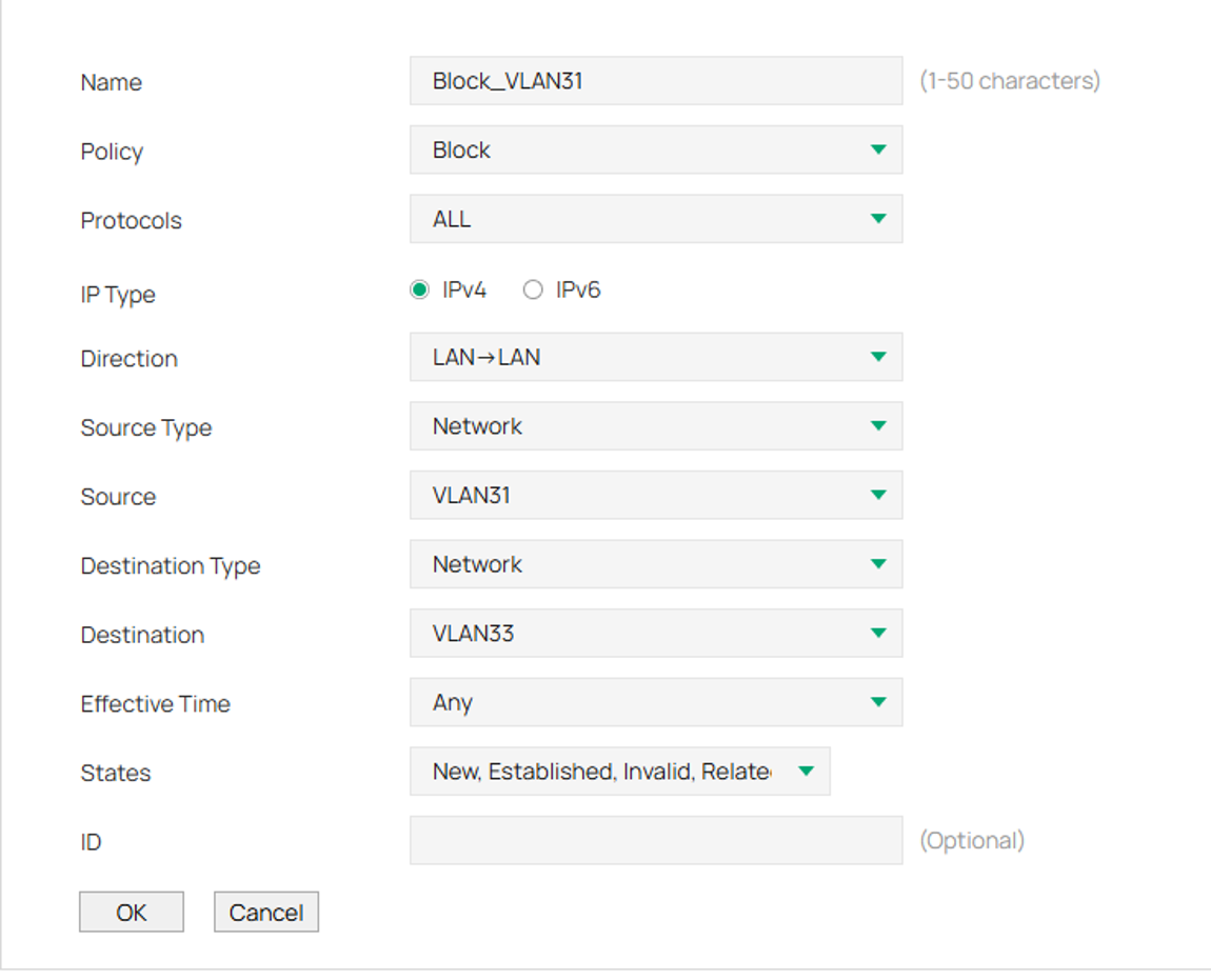
Step 2. Fill in the parameters.
Here the first rule is to block VLAN 31 from communicating to VLAN 33.
Click OK once complete.
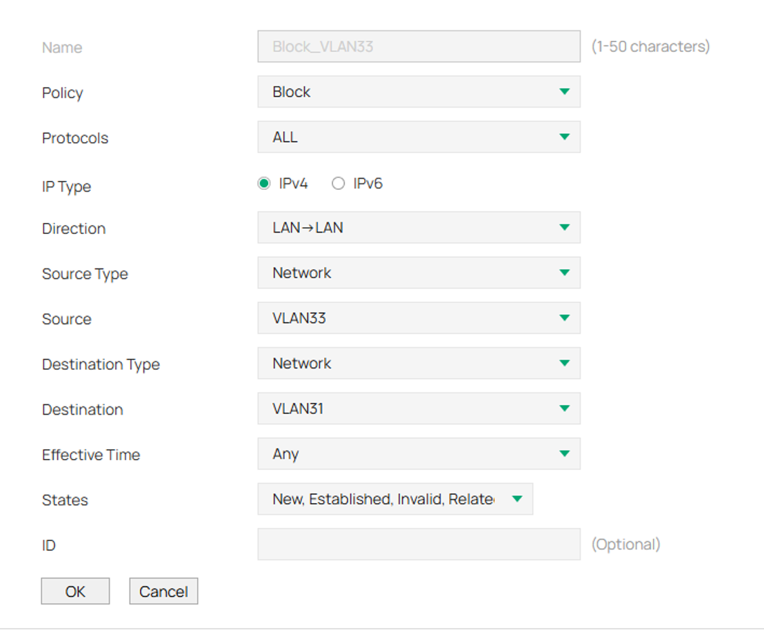
Step 3. Click Add again and create the same rule, but with the Source and Destination reversed.
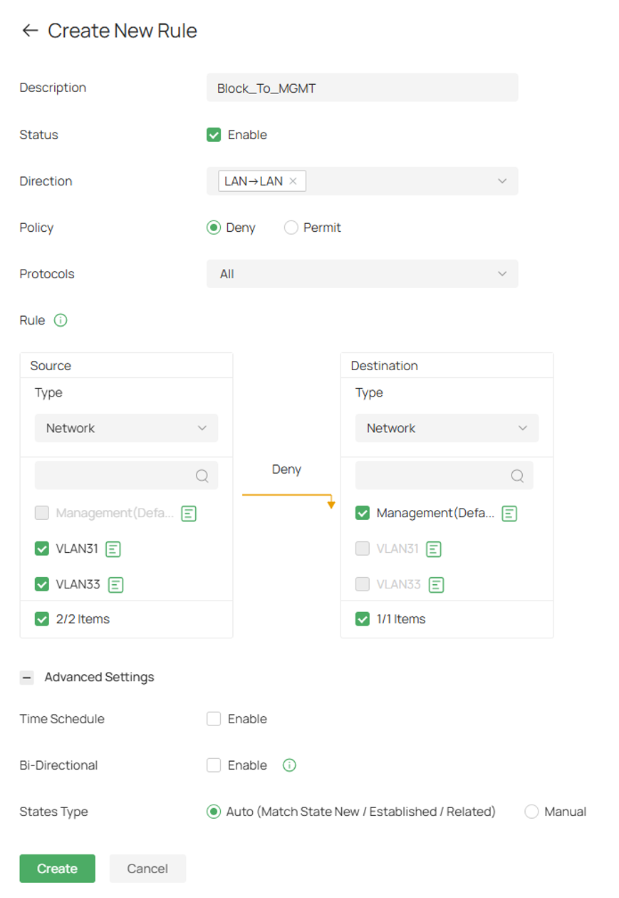
Scenario II: Management VLAN Access (Uni-Directional)
In this example, VLAN 1 (10.0.0.0/24) is configured as the Management VLAN. The objective is to allow devices within the Management VLAN to access resources on VLAN 31 (10.0.31.0/24) and VLAN 33 (10.0.33.0/24) while preventing devices in those networks from initiating communication back to the Management VLAN.
This configuration is commonly used to enable administrators to manage network devices and client systems while limiting unauthorized access to management resources. Since Omada Gateway ACLs include an implicit permit rule, only traffic matching the configured deny rules will be blocked, while all other traffic will continue to be forwarded normally.
Controller Mode
Step 1. Log into the controller and navigate to your Site > Network Config > Security > ACL.
Step 2. Next, go to Gateway ACL and click Create New Rule.

Step 3. Fill in the parameters.
The example below is LAN > LAN deny rule, restricting VLAN 31 and 33 from communicating with the management VLAN.
Click Create once complete.
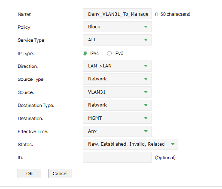
Standalone Mode
Step 1. Log in to your router, navigate to Firewall > Access Control, and click Add.

Step 2. Configure the ACL parameters.
The example below is LAN > LAN deny rule, preventing VLAN 31 devices from communicating with the Management VLAN.
Click OK once complete.
Repeat steps for other VLANs.

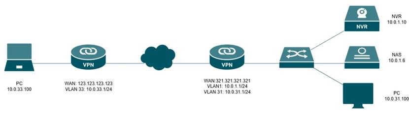
Scenario III: Restrict VPN User Access to Specific Local Resources
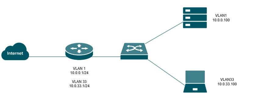
Alt text: Topolgy for this scenario
VPN connections allow remote users and sites to securely access resources located within another network. However, in many deployments, VPN-connected devices should only be permitted to access required resources while being restricted from sensitive systems such as surveillance equipment, management devices, or other critical infrastructure.
In this example, a Site-to-Site VPN is established between two Omada Gateways. A device on the remote network (10.0.33.0/24) will be permitted to access VLAN 31 (10.0.31.0/24) and authorized resources on VLAN 1, such as the NAS (10.0.1.6). However, access to the NVR (10.0.1.10) will be restricted using ACL rules. This approach allows normal VPN connectivity while protecting selected local resources from unnecessary access.
The following example will also be shown through the router that hosts VLAN1 and VLAN31 in the topology above.
Note: If the Omada Gateway is configured as a VPN Server (PPTP, L2TP, OpenVPN, or WireGuard), create an IP Group using the VPN address pool assigned to remote clients. This IP Group can then be used as the source or destination when creating ACL rules to control access between VPN clients and local network resources.
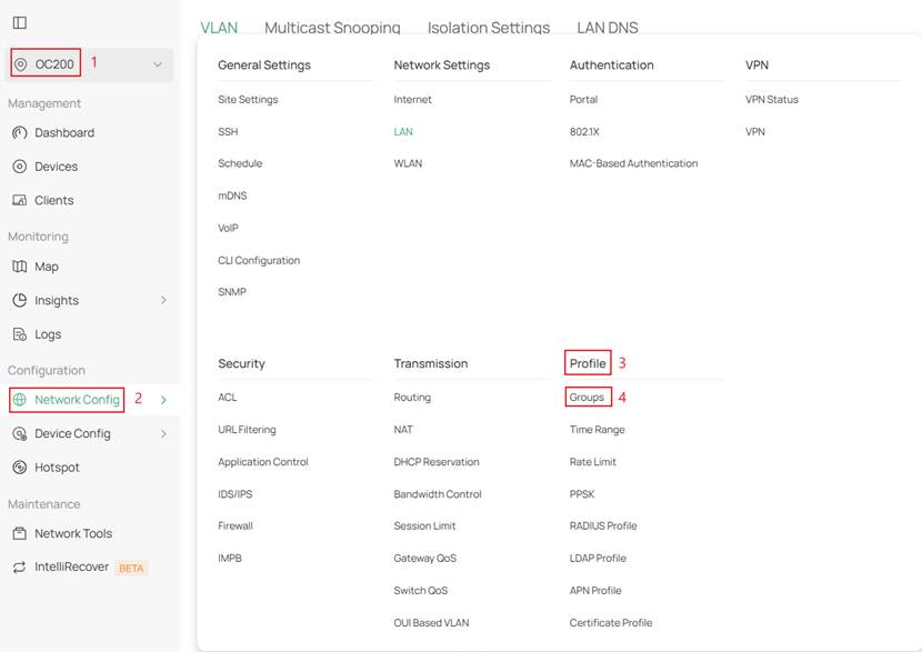
Step 1. Prior to creating the ACL rule, we need to create IP groups to specify the host that we need to restrict access, and another IP group for the remote local subnet from the VPN.
Log into the controller, go to the Site, and then navigate to Network Config > Profile > Groups
Alt text: Navigate to create the IP group
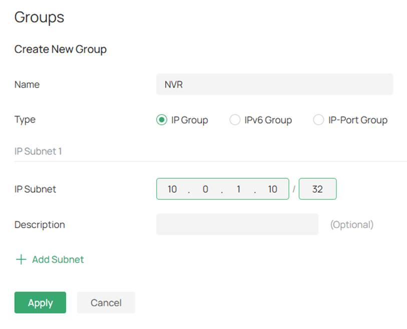
Step 2. Click Create New Group and fill in the parameters.
Here the specified parameters are for the NVR.
Click Apply, then repeat the same steps for the remote subnet at the remote site.

Alt text: Click Create New Group to make the IP groups
Alt text: IP Group for the NVR
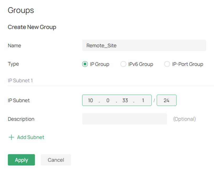
Alt text: IP Group for the remote subnet
Step 3. Next go to Network Config > Security > and click ACL
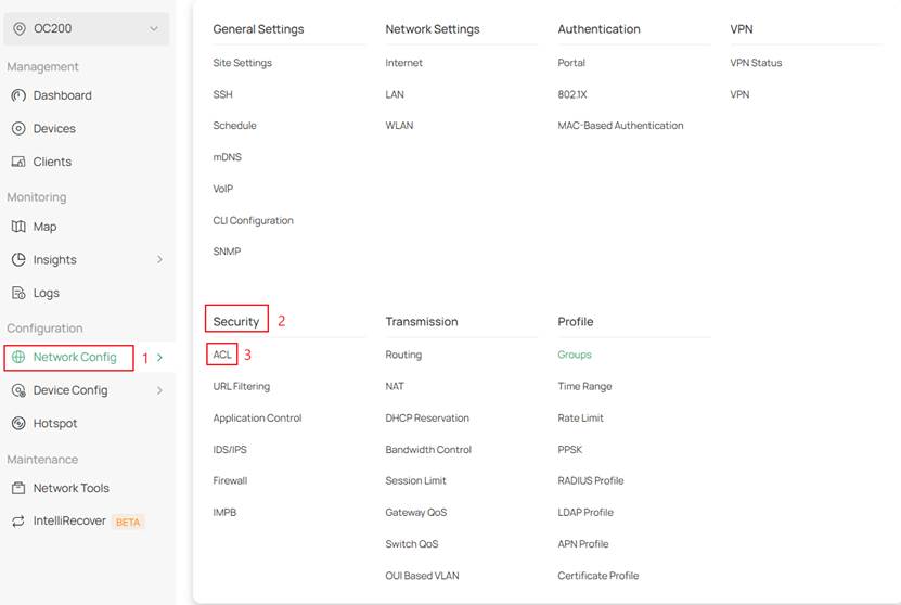
Alt text: Navigate to the ACL page
Step 4. Next, go to Gateway ACL and click Create New Rule

Alt text: Create new rule for the gateway ACL
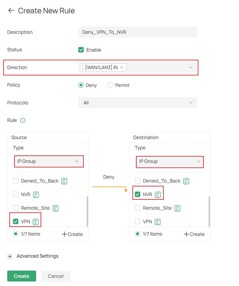
Step 5. Fill in the parameters.
For Direction ensure that the ACL direction corresponds to the WAN interface on which the VPN tunnel is established.
In this example the tunnel is resides on WAN/LAN3 so the option selected in
[WAN/LAN 3] IN.
Click Create once complete.
Alt text: Fill in the parameters for the Gateway ACL to block the VPN to the NVR
Step 1: Create an IP group for the NVR and the remote subnets.
IP Groups are required because Gateway ACLs reference IP Groups rather than individual IP addresses.
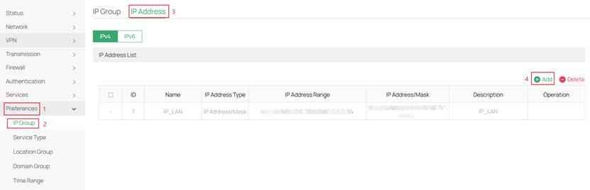
Log into your router and navigate to Preferences > IP Group > IP Address and click Add.
Alt text: Topolgy for this scenario
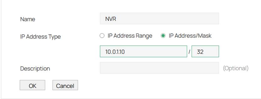
Step 2. Fill in the parameters.
The IP address of the NVR is specified below.
Click OK once complete and repeat the same steps for the remote subnet IP scheme.
Alt text: NVR IP address
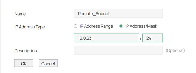
Alt text: Remote subnet IP scheme
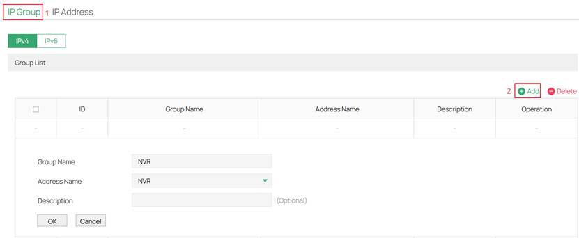
Step 3. Next navigate to IP Group > click Add > and fill in the parameters.
Click OK once complete.
Do this twice, once for the NVR and the other for the remote subnet.
Alt text: IP Group for the NVR
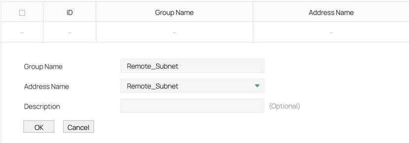
Alt text: IP Group for the remote subnet
Step 4. Lastly create the deny rule.
Go to Firewall > Access Control > and click Add.
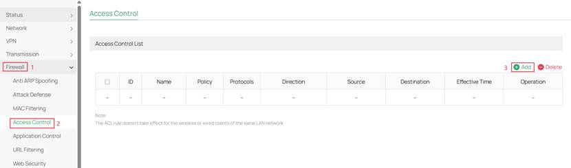
Alt text: Click add to create the deny rule
Step 5. Fill in the parameters for the deny rule.
Here ensure that the correct WAN port is selected for the WAN IN Direction for the policy.
In this router WAN 1 is utilized so [WAN1] IN is selected.
Click OK once complete.
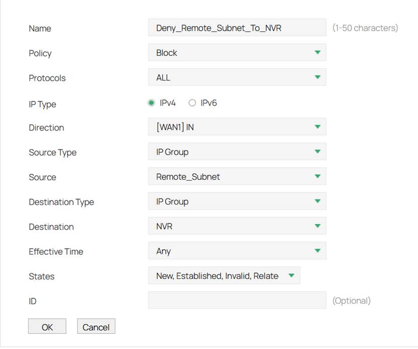
Alt text: Fill in the parameters to block the remote subnet from communicating with the NVR
Scenario IV: Internet Access Only
Alt text: Topolgy for this scenario
In some network environments, it may be desirable to provide Internet access to a group of users while preventing them from accessing internal network resources. Common examples include guest networks, contractor networks, public kiosks, and other untrusted devices that do not require access to corporate systems.
In this example, VLAN 33 (10.0.33.0/24) will be configured as an Internet-only network. Devices within VLAN 33 will be able to access Internet resources, but communication with devices located on VLAN 1 (10.0.0.0/24) will be denied through LAN-to-LAN ACL rules.
Step 1. Log into the controller and navigate to your Site > Network Config > Security > ACL
Alt text: Navigate to create an ACL
Step 2. Next, go to Gateway ACL and click Create New Rule
Alt text: Create new rule for the gateway ACL
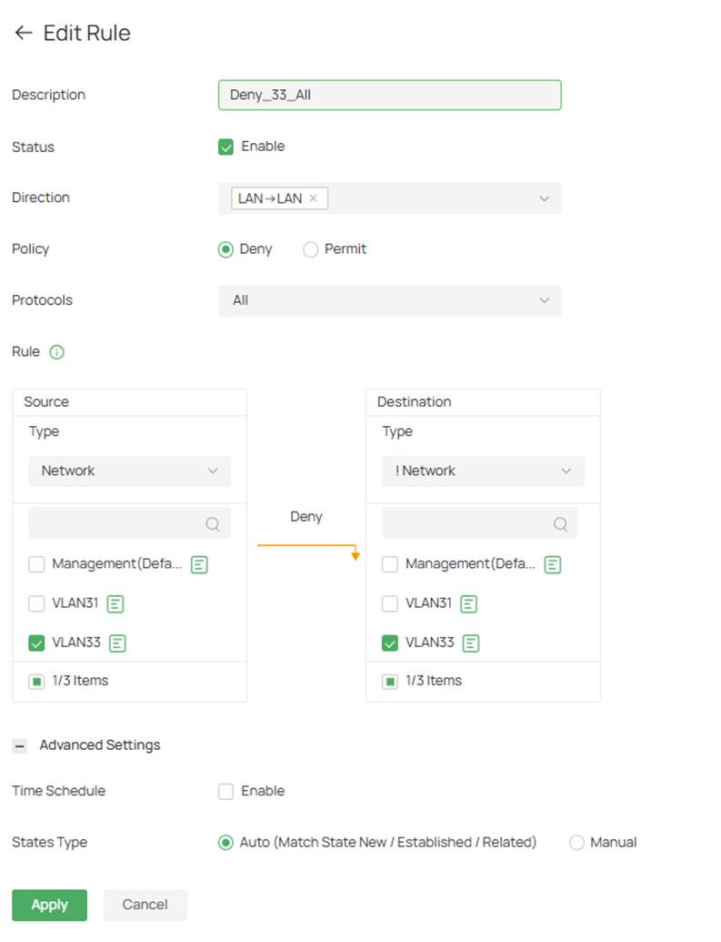
Step 3. Create a deny rule and fill in the parameters.
In this example, VLAN 33 is denied from communicating with all other VLANs on the gateway.
The destination type is configured as !Network. The exclamation mark “!” indicates a logical "NOT" condition, meaning the rule applies to all networks except the network specified. Since VLAN 33 is selected as both the source and excluded destination network, traffic originating from VLAN 33 and destined for any other VLAN will be denied.
Click Apply once complete.
Alt text: Deny rule for VLAN 33
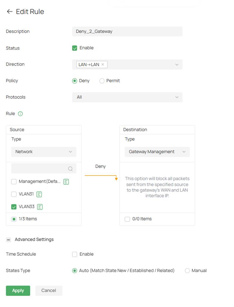
Step 4. Next create another deny rule for the gateway management page so that network does not have access to default gateway UI.
Click Apply once complete.
Alt text: Deny VLAN 33 to the default gateway
Step 1. Log in to your router, navigate to Firewall > Access Control, and click Add.
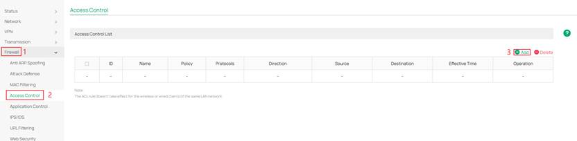
Alt text: Navigate to Access Control to create a policy
Step 2. Create a deny rule and fill in the parameters.
In this example, VLAN 33 is denied from communicating with all other VLANs on the gateway.
The destination type is configured as !Network. The exclamation mark “!” indicates a logical "NOT" condition, meaning the rule applies to all networks except the network specified. Since VLAN 33 is selected as both the source and excluded destination network, traffic originating from VLAN 33 and destined for any other VLAN will be denied.
Click OK once complete
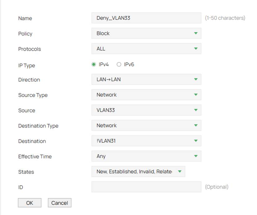
Alt text: Deny rule for VLAN 33
Step 3. Next create a rule to block VLAN 33 from the gateway IP.
Here Me equals all interface gateway IP addresses.
Click OK once complete.
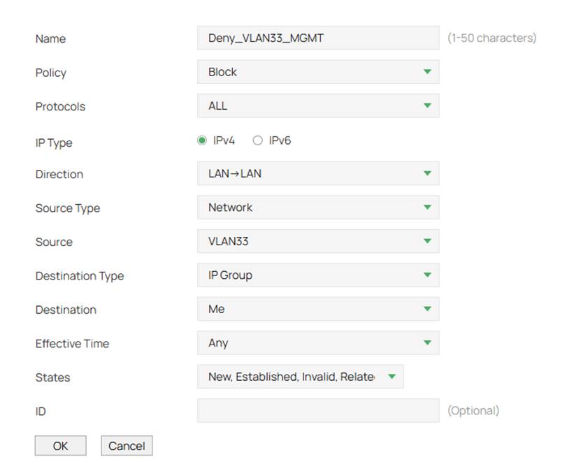
Alt text: Deny rule for VLAN 33 to gateway management IP addresses
By using Gateway ACLs, administrators can control communication between networks, restrict access to sensitive resources, and enforce security policies across the network. Whether isolating VLANs, protecting management networks, limiting VPN access, or providing Internet-only connectivity, ACLs provide a flexible method of controlling traffic flow while maintaining access to authorized resources.
Get to know more details of each function and configuration please go to Download Center to download the manual of your product.
Q1: Why can devices in the same VLAN still communicate after creating a Gateway ACL?
A1: Gateway ACLs only inspect traffic that traverses the gateway. Traffic between devices in the same VLAN is switched locally and does not pass through the gateway. To restrict communication within the same VLAN, use Switch ACLs, Port Isolation, or separate VLANs.
This article applies to: Omada Gateway, Omada Controller v6.2
Keyword: ACL, Access Control, Segmentation, Isolation, Management VLAN, Network Isolation
[CZ1]We usually call it 'Gateway'
[CZ2]Better be 'Gateway ACL in Controller Mode'
[CZ3]We currently also support IP-port groups, IPv6 groups, IPv6-port groups, location groups, domain name groups, and more. Please refer to the latest software.
[TC4]I only referred to the relevant parameters. If all parameters are posted then it would be long. Please let me know if you want me to implement them
[CZ6]Better be 'Gateway ACL in Standalone Mode'
[CZ7]Missing 'Name'
[CZ8]Missing 'Service Type'
[CZ9]They all start with a 0.
[CZ10]missing 'VPN IN'
[CZ11]missing 'Location' ,'Location Group' and 'Domain Group'
[CZ12]missing 'Location' ,'Location Group' and 'Domain Group'
