


Omada Management VLAN Configuration Guide for Business Networks


Contents
Part 1. Prepare the Management VLAN Environment
Part 2. Deploy Management VLANs and Configure Client Access
Part 3. Configure Gateway Integration and Inter-VLAN Routing
Introduction
This article explains how to deploy separate management VLANs for Omada switches and access points (APs) while using a dedicated client VLAN. The default VLAN is repurposed by changing its VLAN ID and subnet, allowing client devices to remain isolated from the management network. This guide also covers how to add new devices to an existing production network without disrupting service.
In many business deployments, administrators separate the management traffic for the Controller, gateway, switches, and APs from client traffic. By placing infrastructure devices and client devices in different VLANs, users cannot directly access the management interfaces of network devices, improving network security and simplifying network management.
This guide is intended for business network deployments and includes the recommended procedure for integrating new devices into an existing network. For smaller or home office environments, refer to How to configure Management VLANs for Omada Switches and APs (for SOHO scenario).
A typical business network topology is shown below. In this design, the core switch performs Layer 3 routing and acts as the DHCP server for all VLANs. The gateway is responsible only for routing traffic between the internal network and the Internet.
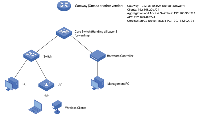
As shown in the topology, the network will be configured as follows:
- VLAN 20 – Client VLAN (192.168.20.0/24)
- VLAN 30 – Switch management VLAN (192.168.30.0/24)
- VLAN 40 – AP management VLAN (192.168.40.0/24)
- VLAN 50 – Core switch/Controller/MGMT PC (192.168.50.0/24)
VLAN 1 is removed from production use. The gateway, core switch, and Omada Controller continue to use the default management network, but its VLAN ID is changed to a new value. Their management IP addresses can also be modified as needed.
Requirements
- Omada Controller (Software Controller / Hardware Controller / Omada Cloud-Based Controller, v6.2 and above)
- Omada Smart, L2+ and L3 switches
- Omada APs
- Omada Gateway
Configuration
Part 1. Prepare the Management VLAN Environment
Step 1. Connect the Hardware Controller and Adopt the Core Switch
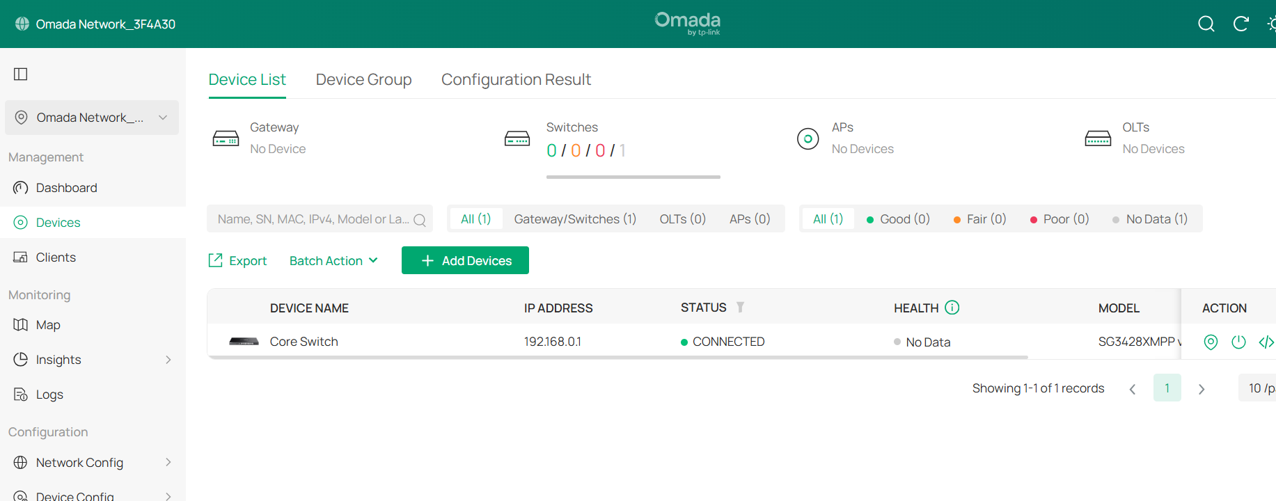
Connect the hardware controller to the core switch, and then connect the management PC to the hardware controller. Proceed with adopting the core switch through the hardware controller.
Since the DHCP server has not been configured yet, both the core switch and the hardware controller are currently using fallback IP addresses:
- Core Switch: 192.168.0.1
- Hardware Controller: 192.168.0.253
Configure the management PC with a static IP address in the 192.168.0.0/24 subnet (for example, 192.168.0.100) so that it can access the hardware controller. Once connected, proceed with the device adoption process.
Step 2. Create the required VLAN networks
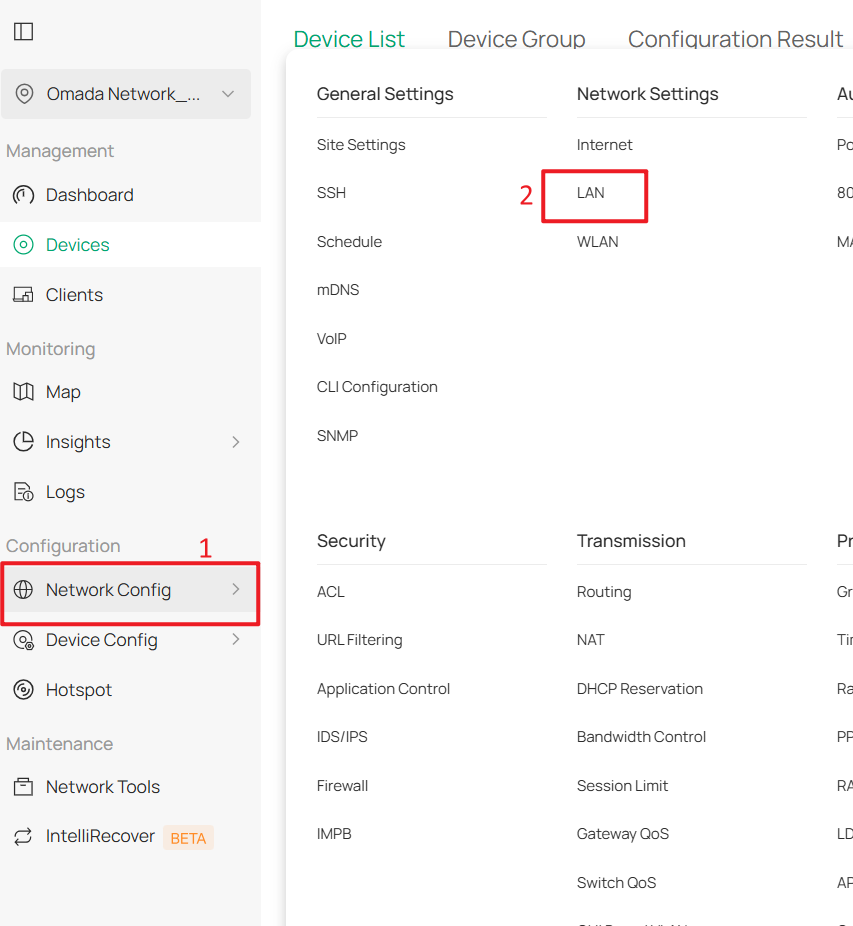
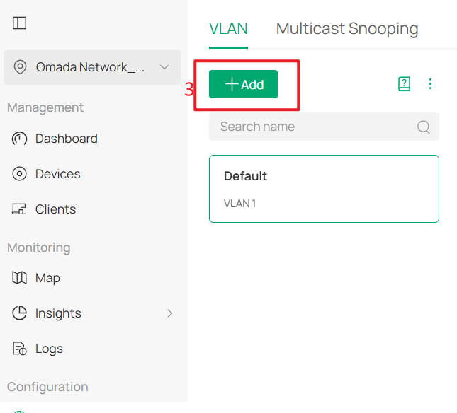
First, create the Client Network (VLAN 20), SW MGMT Network (VLAN 30), AP MGMT Network (VLAN 40) and Core MGMT Network (VLAN 50). Go to Network Config > Network Settings > LAN > VLAN, click +Add to create new LAN network.
The following example shows the configuration for the Client Network (VLAN 20).
Set the DHCP Server Device to Core Switch and the DHCP Mode to DHCP Server. Then configure the IP Address/Subnet, DHCP Range, DNS Servers, and Default Gateway.
In this example, the following settings are used:
- IP Address/Subnet: 192.168.20.1/24
- DHCP Range: 192.168.20.0/24
- Primary DNS Server: 8.8.8.8
- Secondary DNS Server: 1.1.1.1
- Default Gateway: 192.168.20.1
Once the settings have been entered, click Next to proceed to the Select Device Port page. Leave the port assignment unchanged by clicking Skip, and then click Apply to save and apply the configuration.
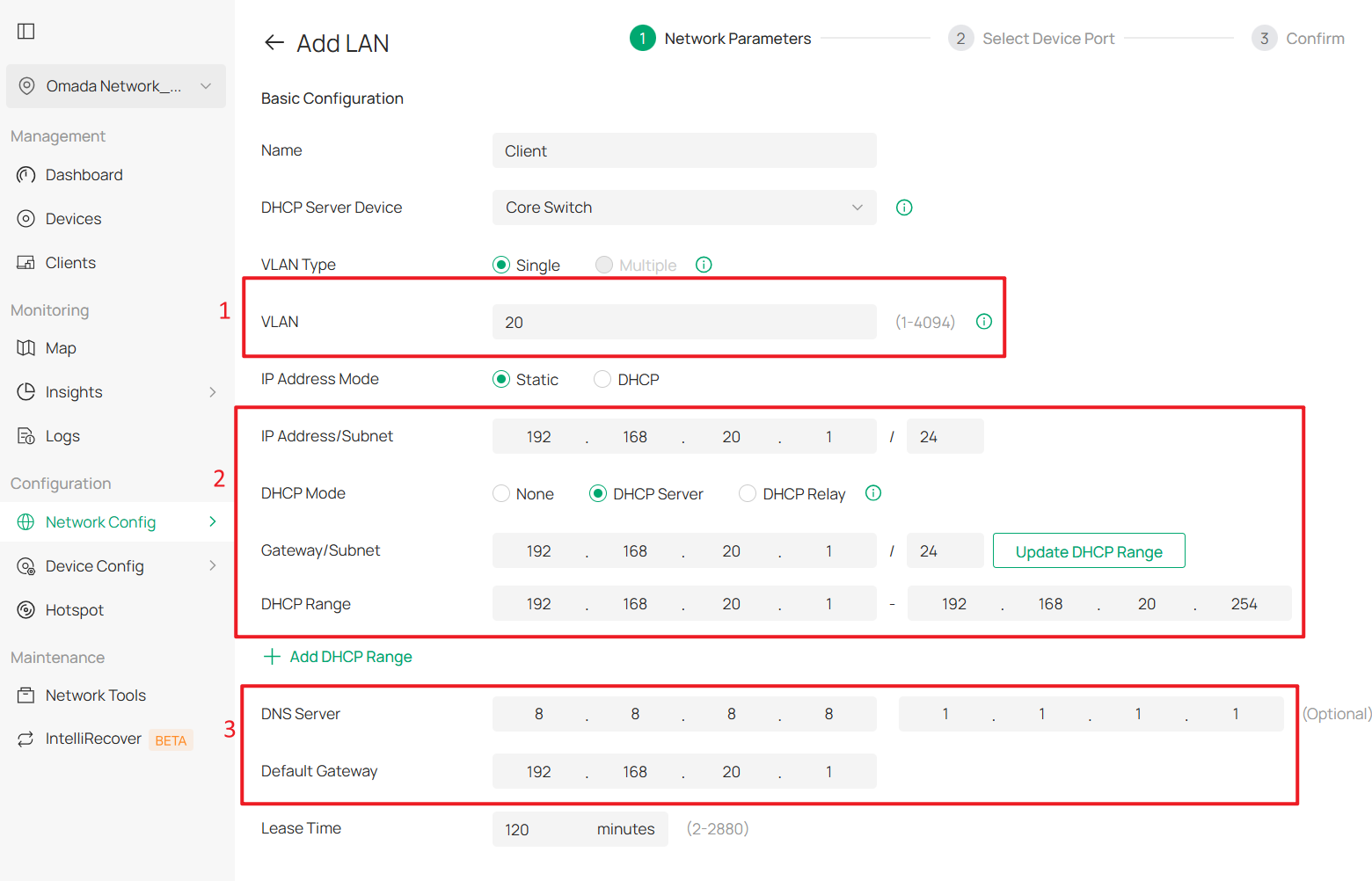
Then create SW MGMT Network, AP MGMT Network and Core MGMT Network as the same method.
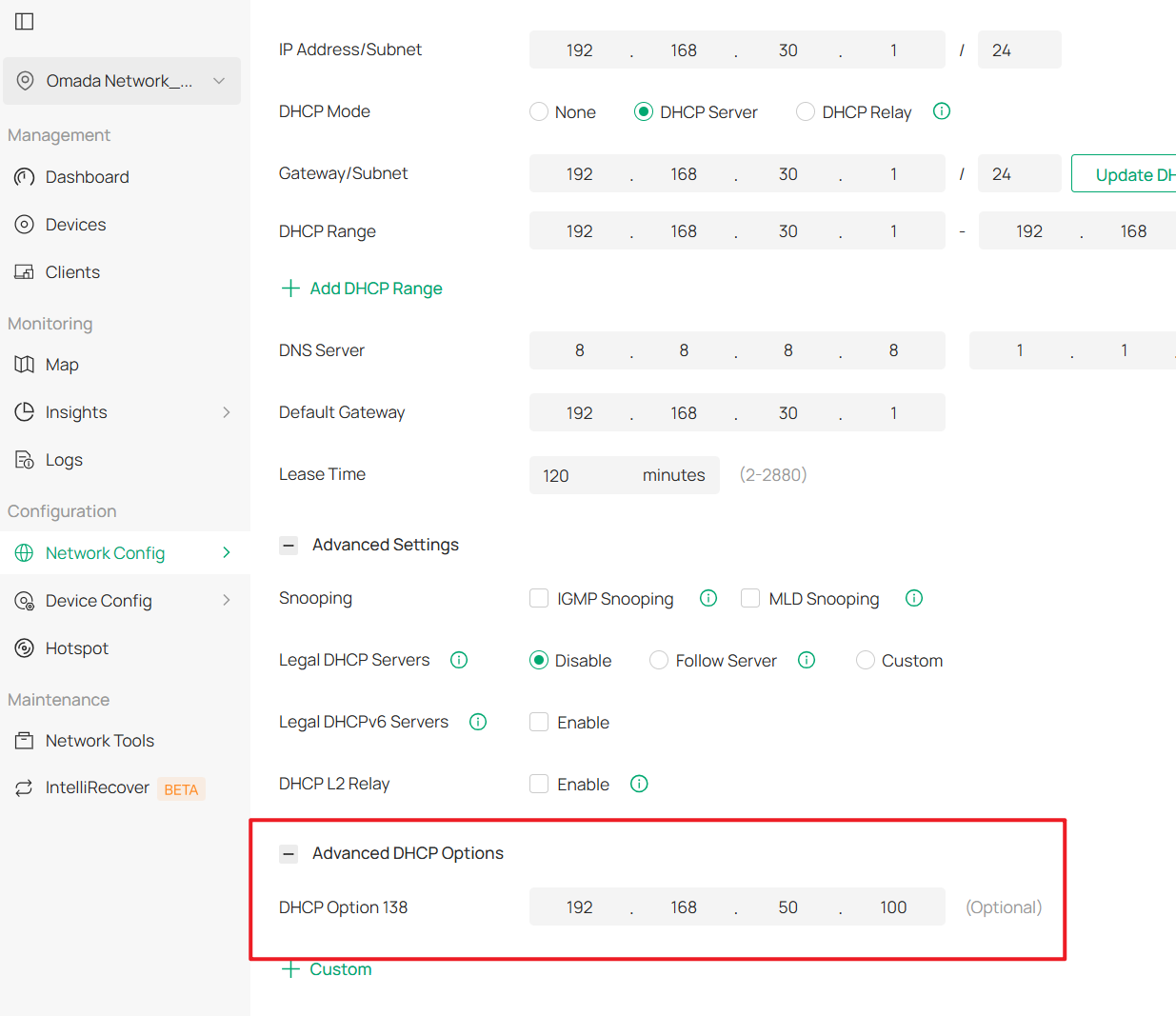
Note that the SW MGMT and AP MGMT Networks must be configured with DHCP Option 138.
DHCP Option 138 is used to inform devices of the Controller’s IP address during the DHCP process. This configuration is required because eventually all network devices will not be in the same VLAN; they need DHCP Option 138 to discover the Controller and be adopted.
In this example, DHCP Option 138 is set to 192.168.50.100, and the Controller will be assigned this IP address in later steps.
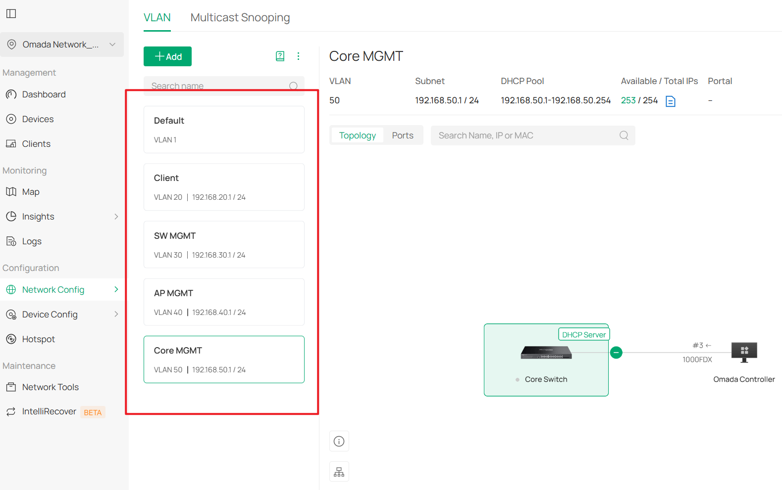
The final result should be like this:
Step 3. Configure the Core Switch port for the Controller
Go to Device Config > Switch > Switch Ports > Port Settings, and click Edit on the port that will be used to connect the Controller (different from the port currently in use). After changing the Core Switch’s Management VLAN, we will move the Controller to this port.
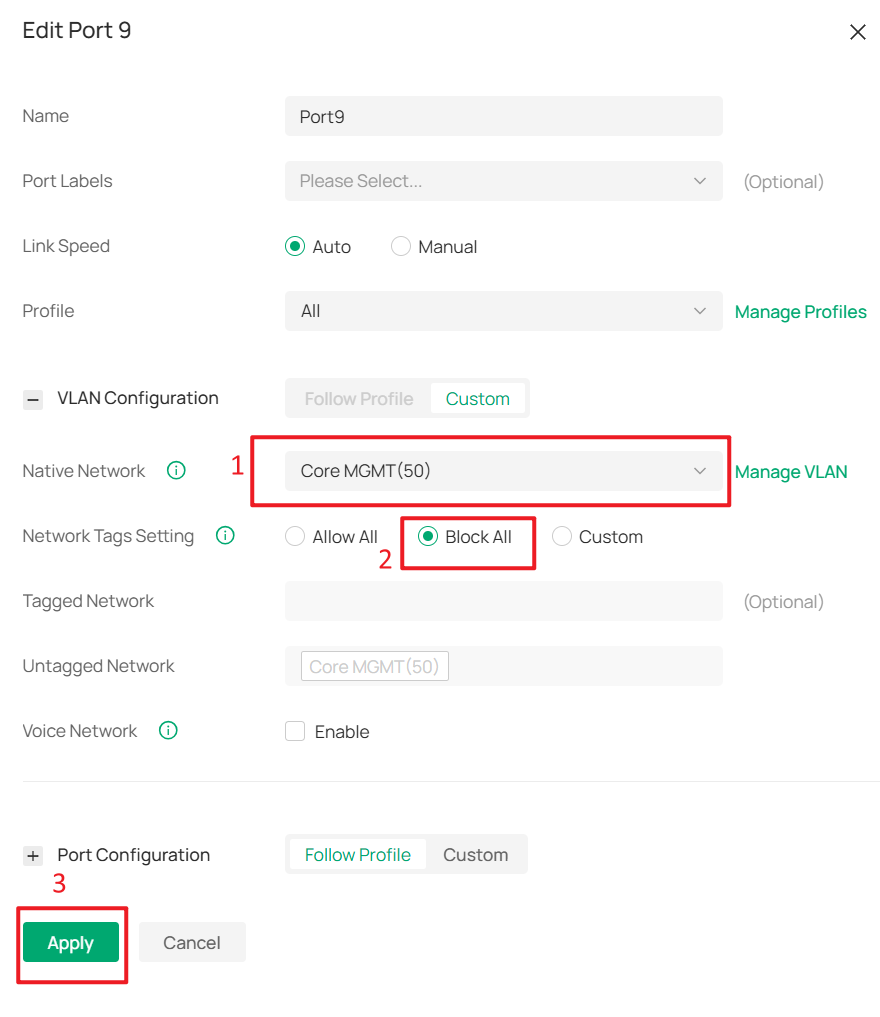
In this example, the Controller will be moved to port 9, so modify the port profile of port 9.
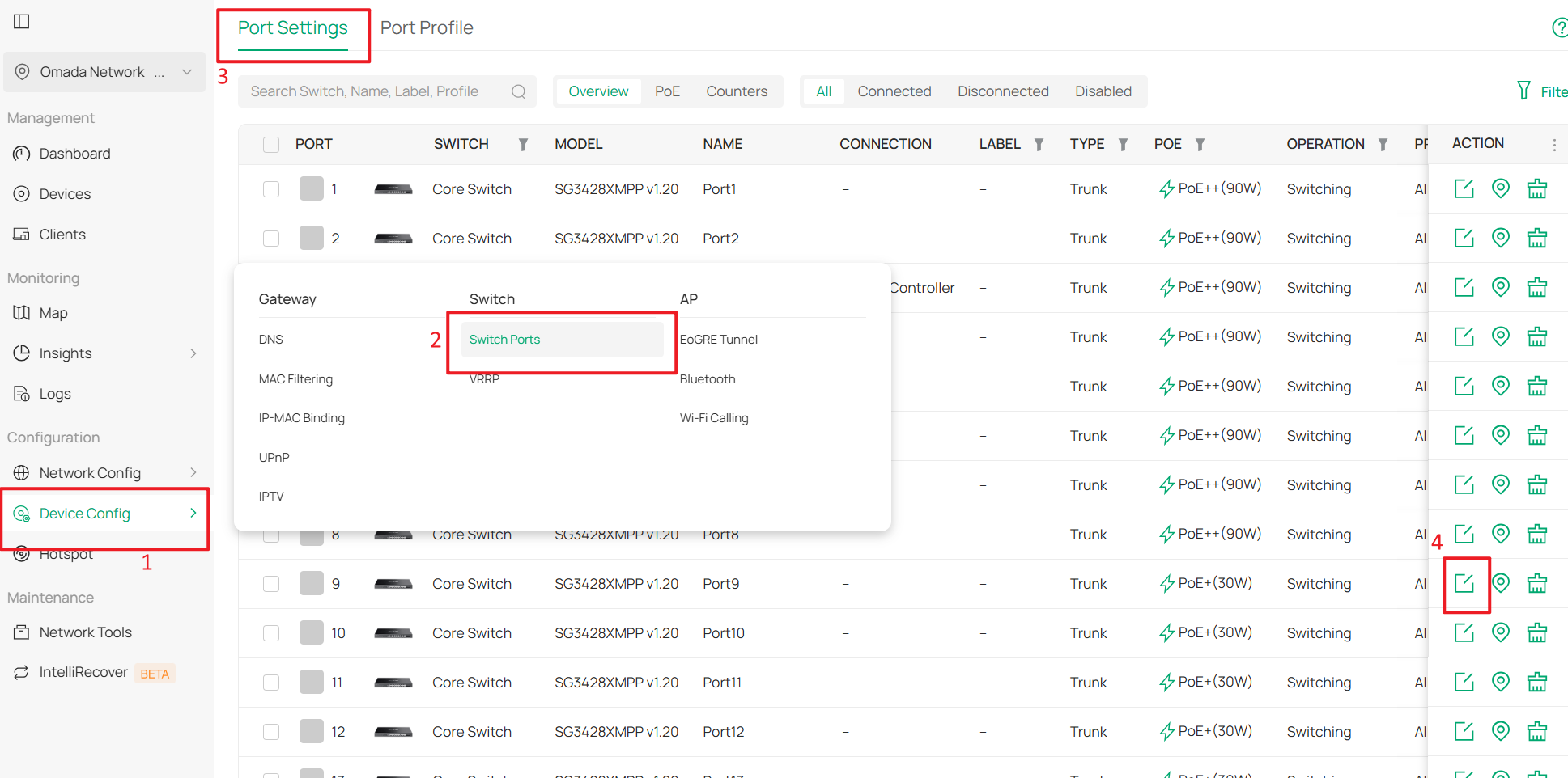
Set the Native Network to Core MGMT, and set Network Tags Setting to Block All, and click Apply to apply the configuration.
Step 4. Change the Management VLAN of the Core Switch.
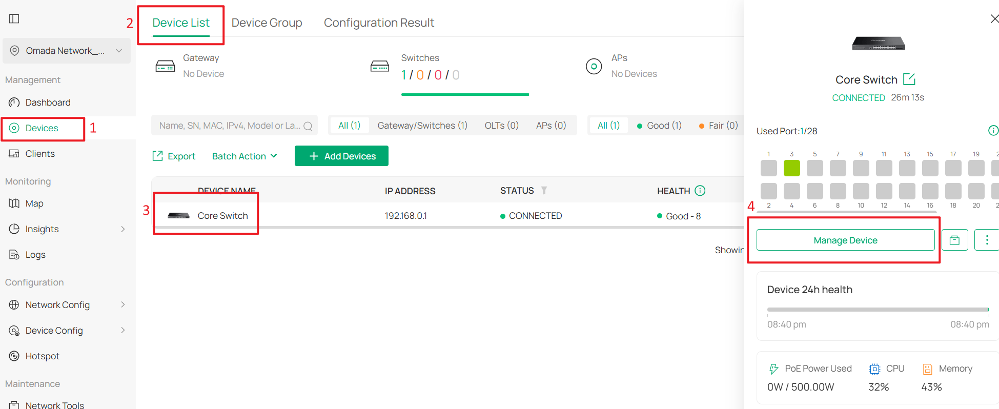
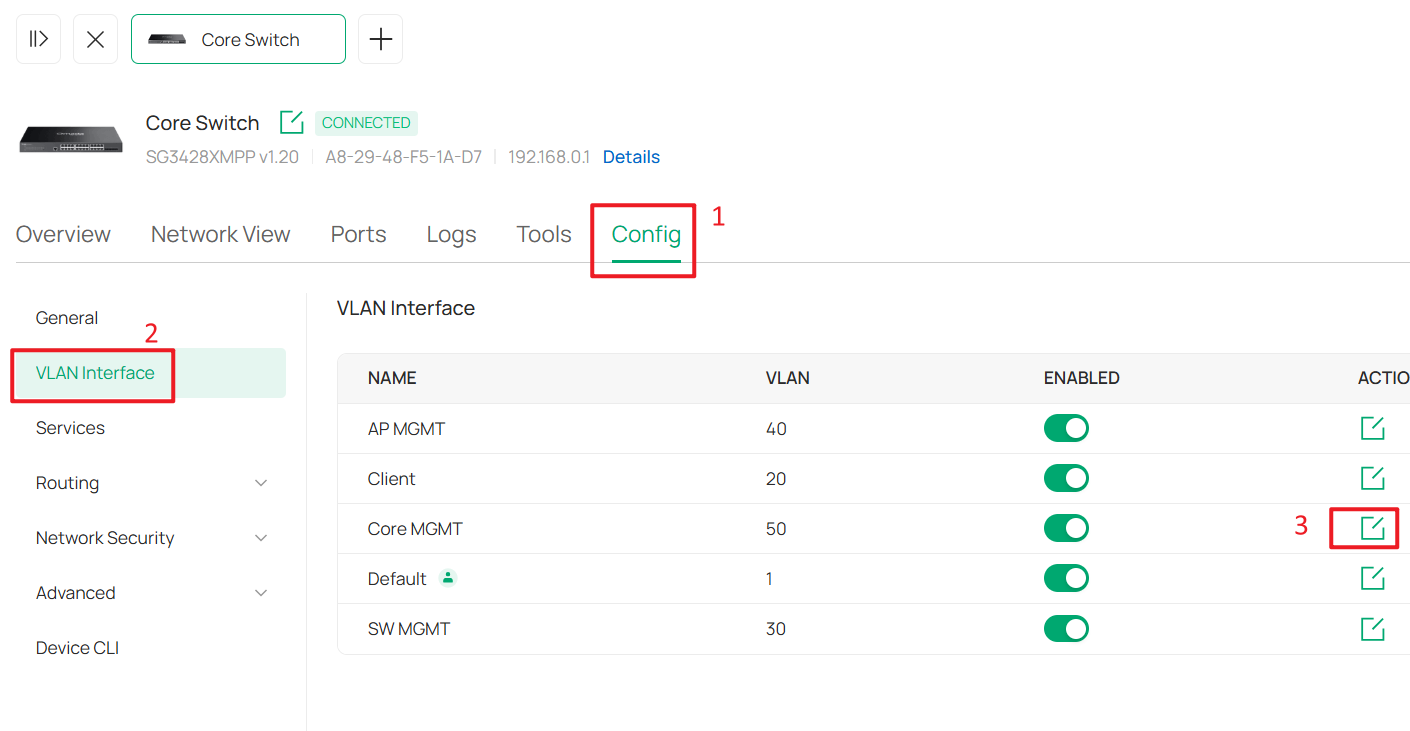
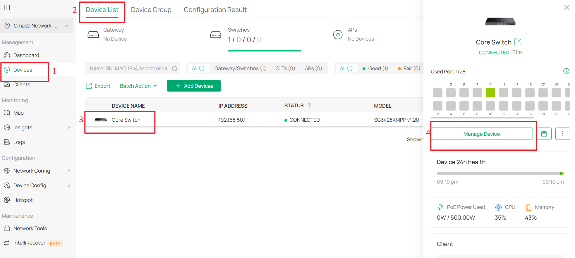
Go to Devices > Device List, click the Core Switch and Manage Device to enter its private configuration page, then go to Config > VLAN Interface, and click Edit for Core MGMT.
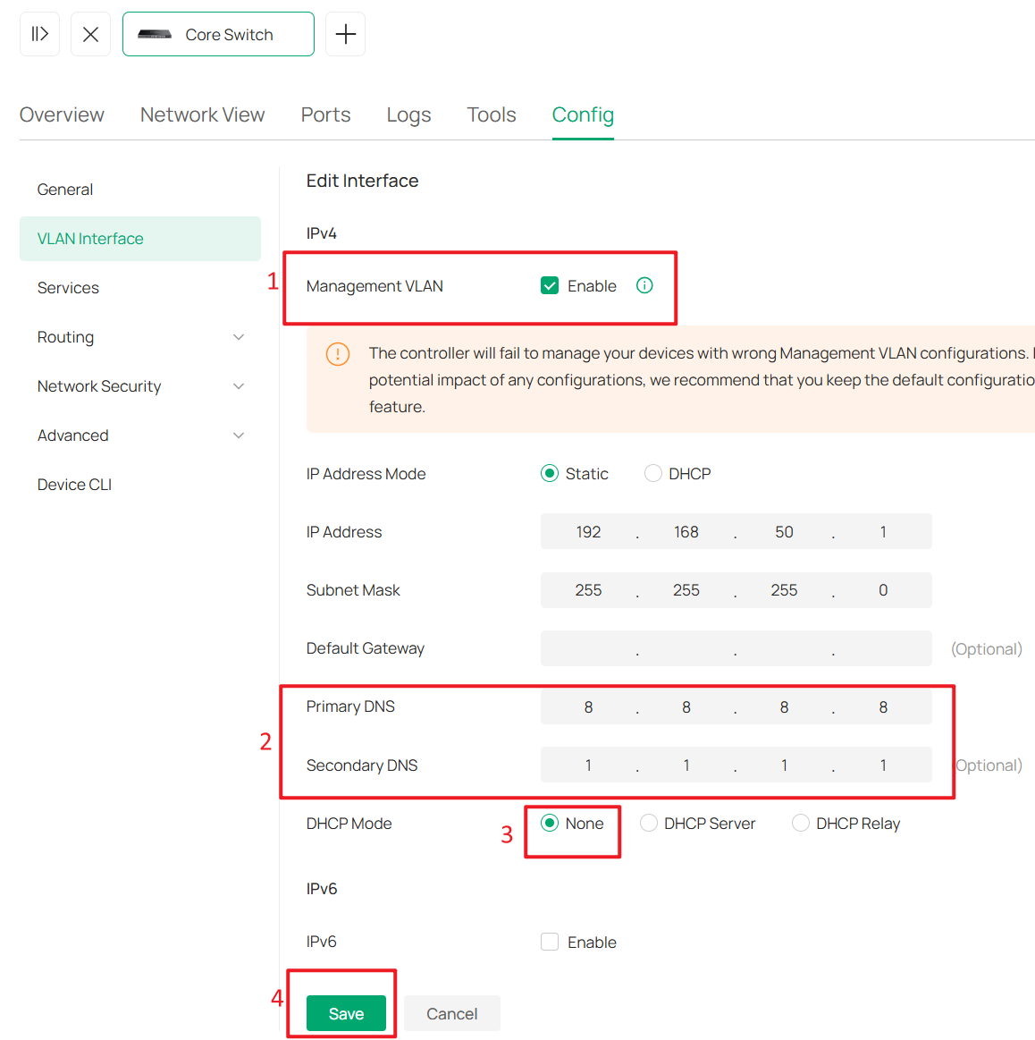
Enable Management VLAN, configure the DNS Server, change the DHCP Mode to None, and click Save to apply the configuration.
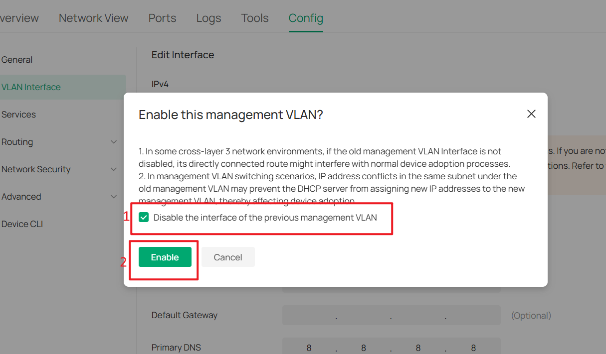
This pop-up is a confirmation prompt asking whether you want to change the management VLAN. Please check "Disable the interface of the previous management VLAN", and then click "Enable".
Step 5. Update the IP Addresses of the Controller and Management PC
Now, the Core Switch IP address will switch to the 192.168.50.1/24. Therefore, we need to configure the Controller and the management PC with static IP addresses in the same subnet to continue managing the devices.
To configure a static IP address on the hardware controller:
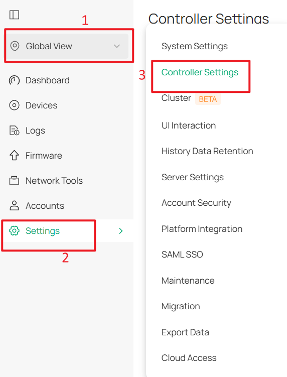
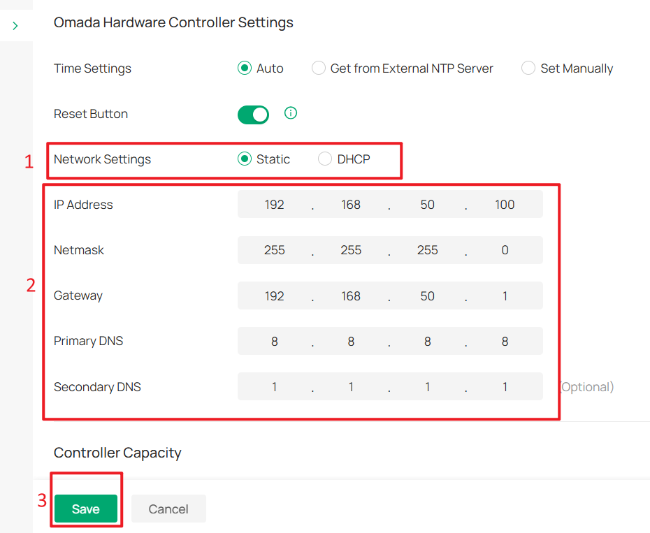
Go to Global View > Settings > Controller Settings, set Network Settings to Static, then configure the IP Address (in this example, 192.168.50.100), Gateway and DNS server. Then click Save to apply the configuration.
After configuring the Controller’s IP address, you also need to change the IP address of the management PC to the same subnet with the Controller, such as 192.168.50.101.
Once the management PC IP address has been updated, enter the new IP address of the hardware controller in your browser to access the Controller Web UI again.
Step 6. Reconnect the Controller to the Configured Switch Port
In Step 3, we changed the Native Network of the Core Switch port connected to the Controller to Core MGMT.
Now, after changing the IP addresses of the Controller and the management PC, reconnect the Controller to this port to ensure proper communication between the Controller and the Core Switch.
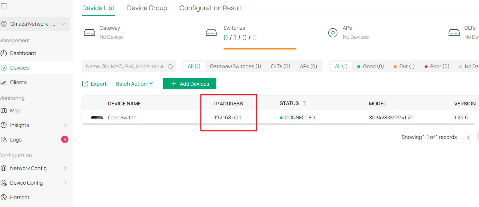
After completing this step, the Core Switch should be successfully rediscovered by the Controller.
Part 2. Deploy Management VLANs and Configure Client Access
Step 1. Reconfigure the Default Network
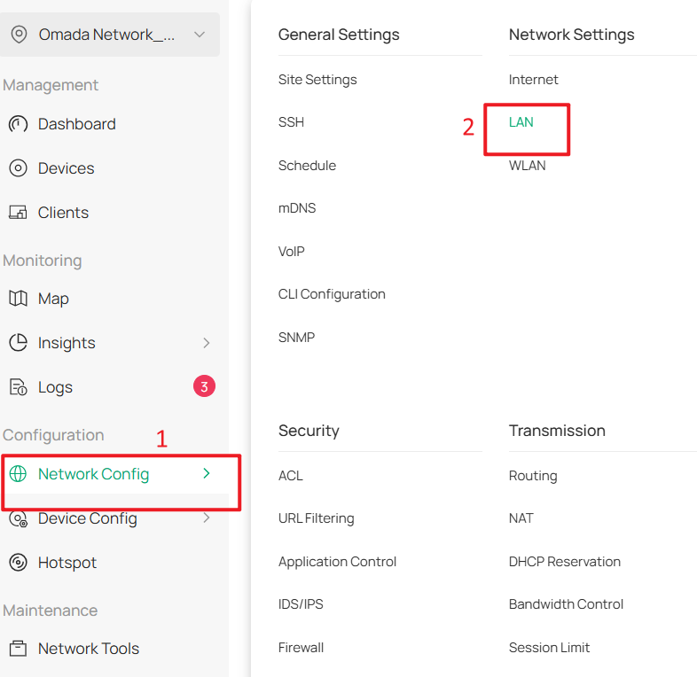
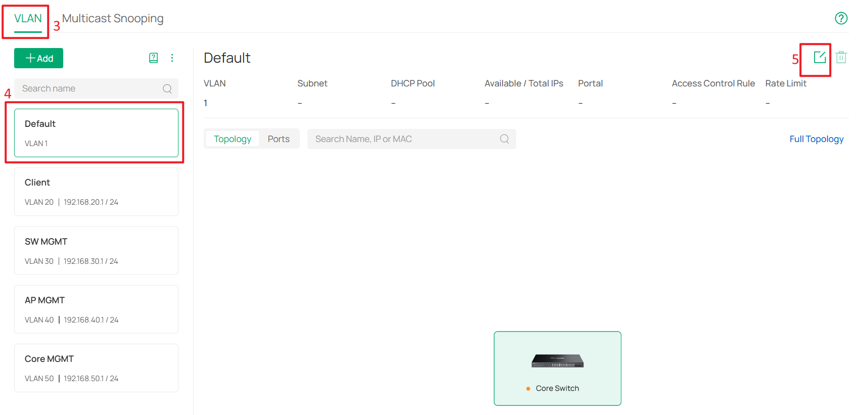
Go to Network Config > Network Settings > LAN > VLAN, select Default, and click Edit.
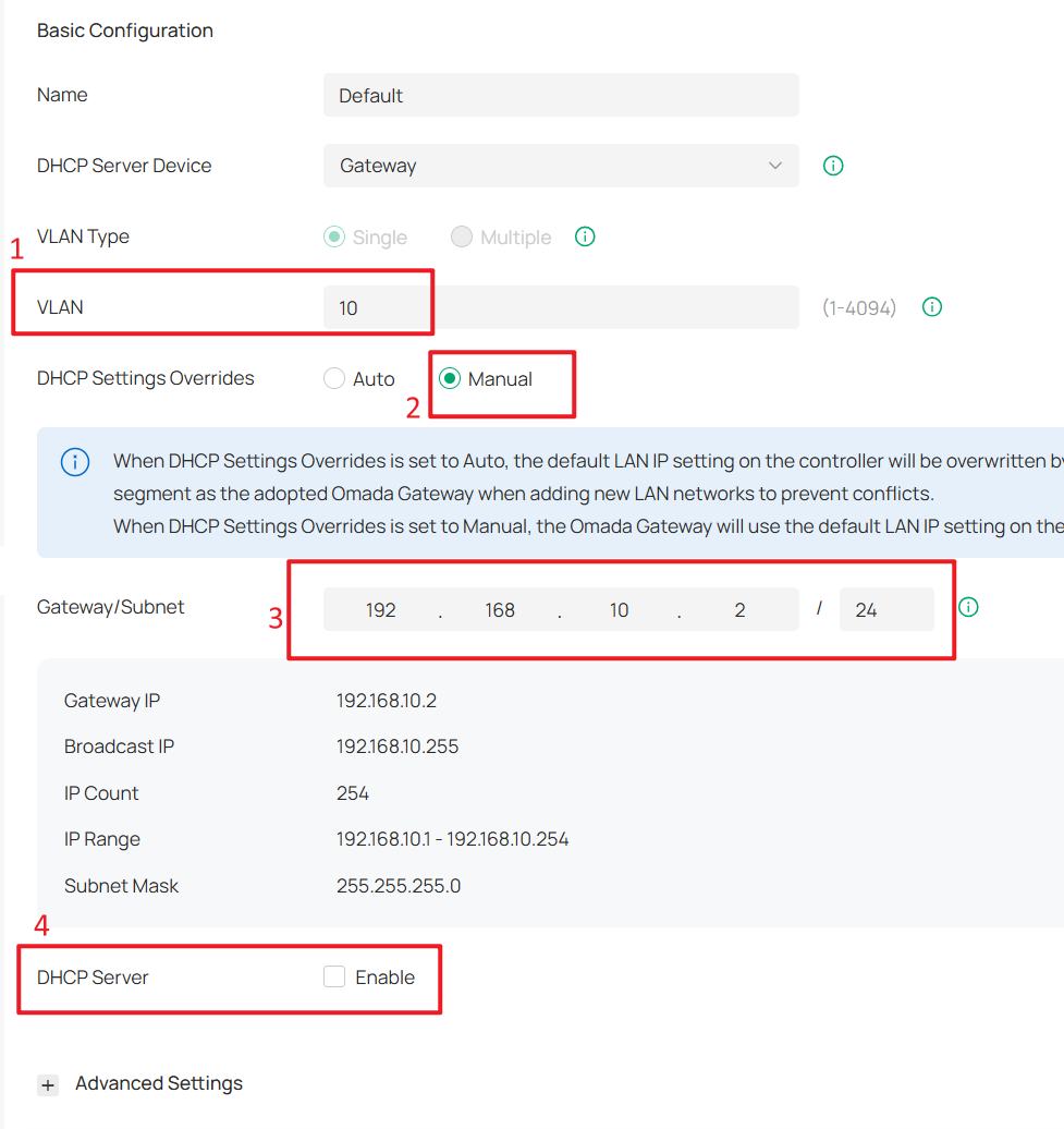
Change the VLAN ID and subnet IP address so that the Default Network no longer uses VLAN 1. In this example, change it to VLAN 10 and set DHCP Settings Overrides to Manual.
For the Gateway/Subnet, set it to 192.168.10.x/24. In this example, it is set to 192.168.10.2, which is the gateway IP address. This helps the Controller identify the Omada gateway later.
If you do not have an Omada gateway, you can still enter the gateway IP address here.
Finally, disable the DHCP Server.
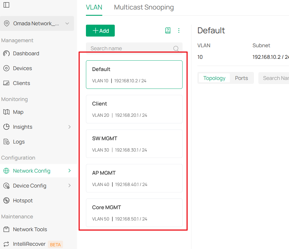
The final result should appear as shown below:
Step 2. Configure the Core Switch as the DHCP server for the Default Network.
Go to Devices > Device List, click the Core Switch and Manage Device to enter its private configuration page, then go to Config > VLAN Interface and click Edit for Default.
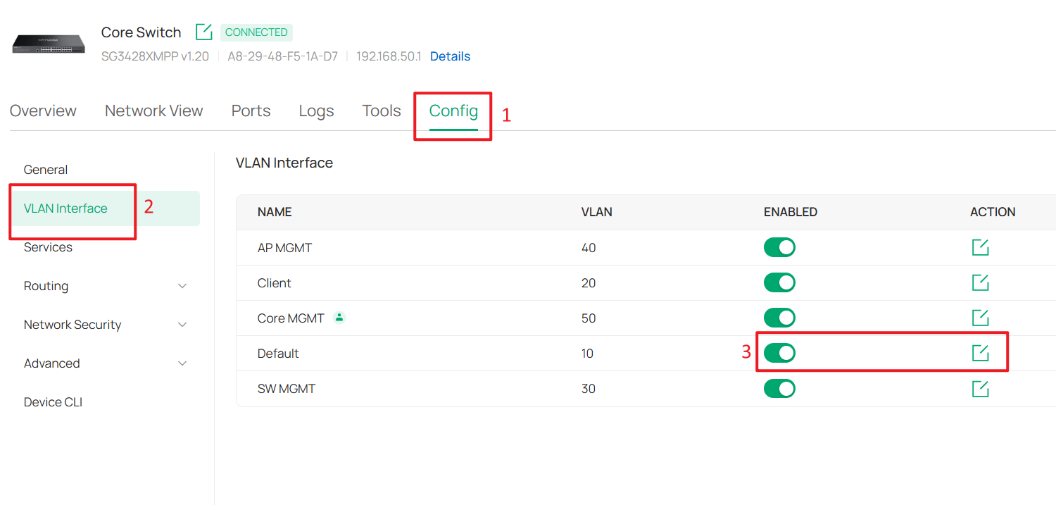
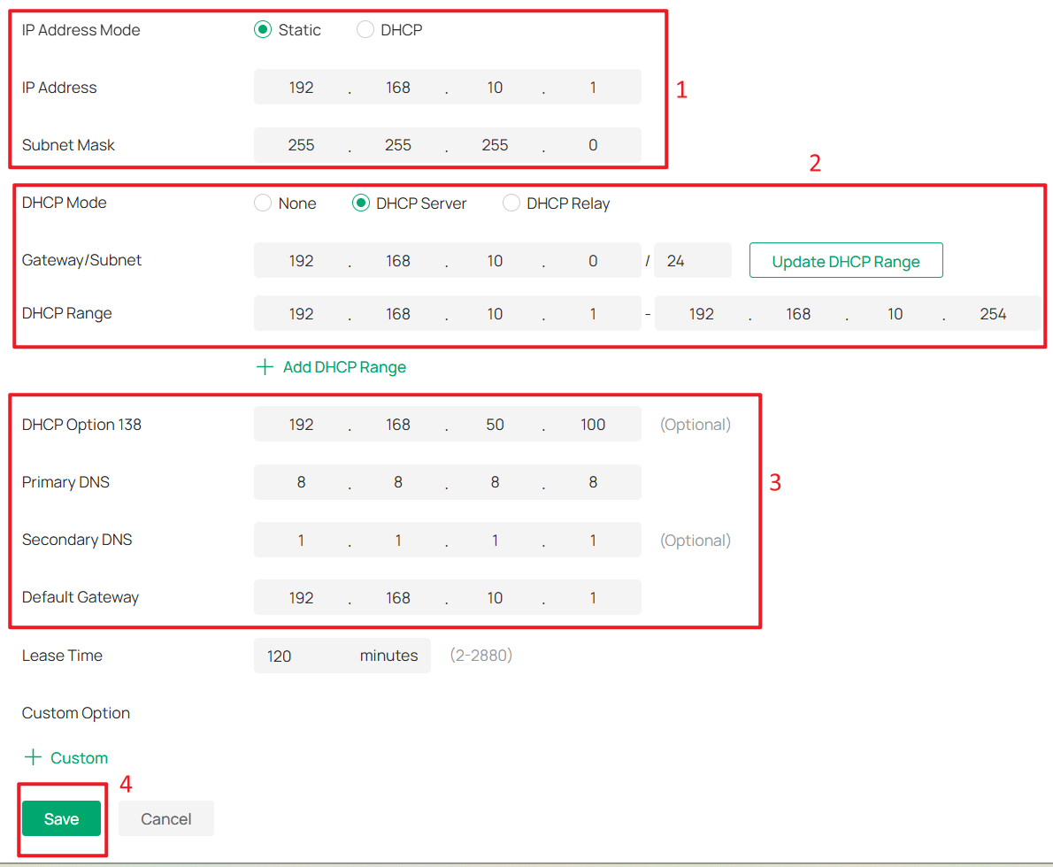
Set IP Address Mode to Static and DHCP Mode to DHCP Server. Configure the IP Address, DHCP Range, DHCP Option 138 and Default Gateway.
In this example, these are set to 192.168.10.1, 192.168.10.0/24, 192.168.50.100 and 192.168.10.1. Configure the DNS servers as needed, then click Save to apply the settings.
Step 3. Connect and adopt all switches and APs.
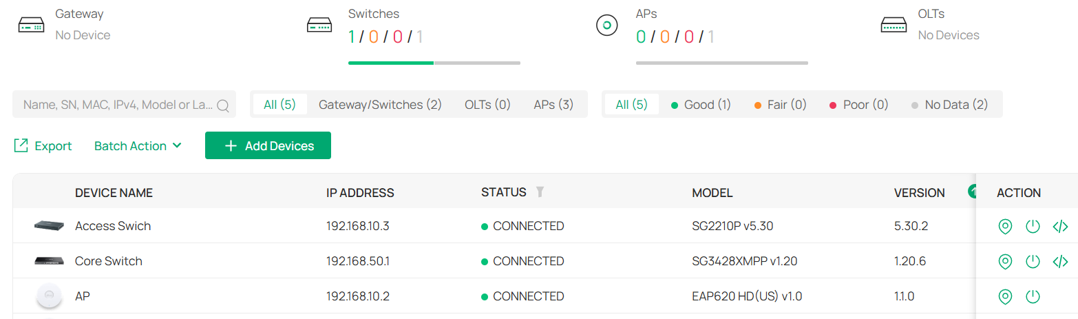
After the switches and APs are connected, they should obtain IP addresses from the Default Network (subnet 192.168.10.0/24).
Step 4. Configure the Switch Management VLAN
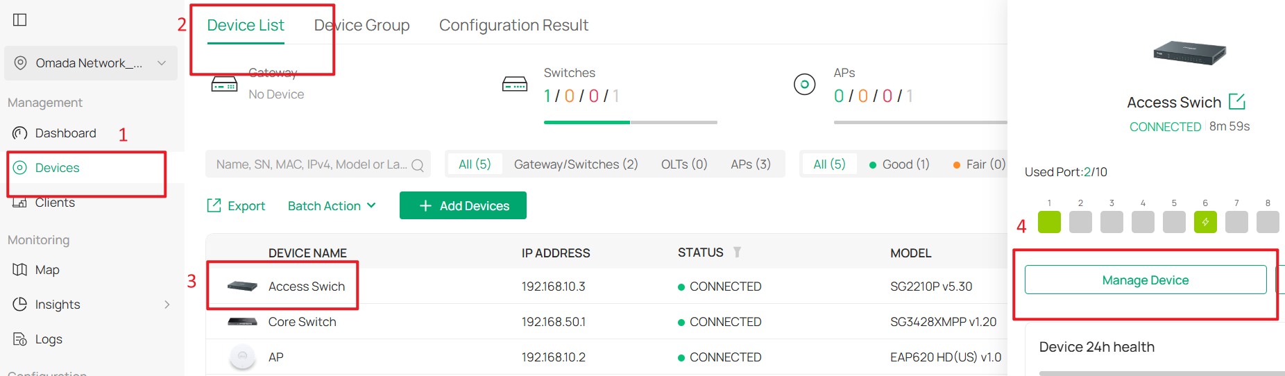
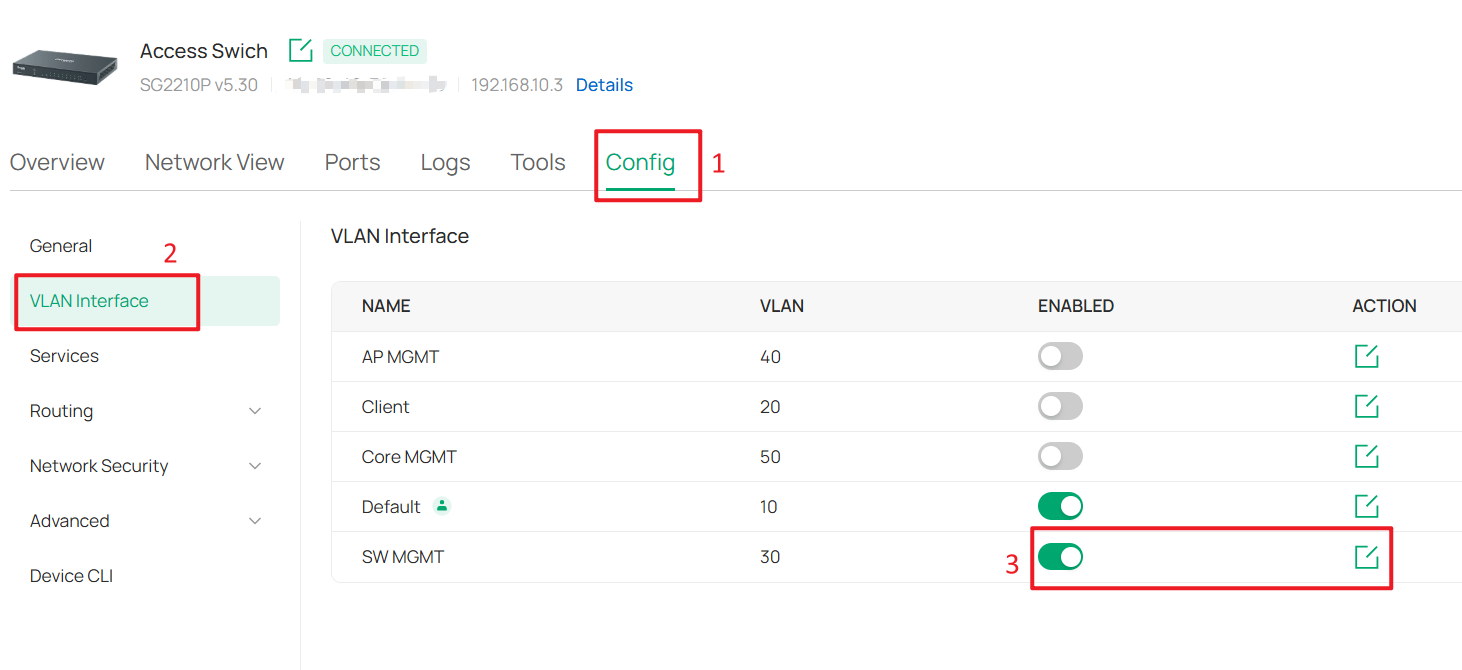
Go to Devices > Device List, click a switch and Manage Device to enter its private configuration page, then go to Config > VLAN Interface, Enable SW MGMT and click Edit.
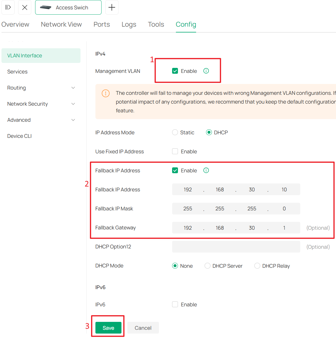
Tick the Enable box to set this VLAN interface as the Management VLAN. Optionally, configure the Fallback IP, and Fallback Gateway. These settings are used when the device fails to obtain an IP address via DHCP, ensuring continued management access.
In this example, they are set to 192.168.30.10, 255.255.255.0, and 192.168.30.1. Click Save.
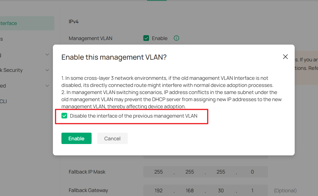
In the pop-up window, check Disable the interface of the previous management VLAN.
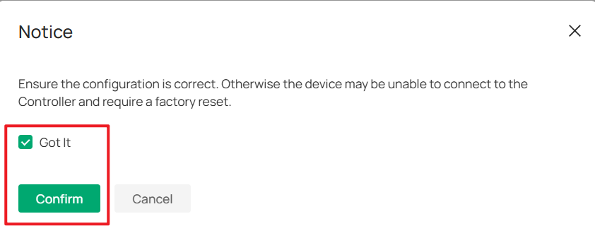
Wait a moment for the configuration to take effect. The switch may be reprovisioned during this process. Once the Management VLAN switch is complete, you will find that the switch’s IP address has changed to the subnet of SW MGMT.
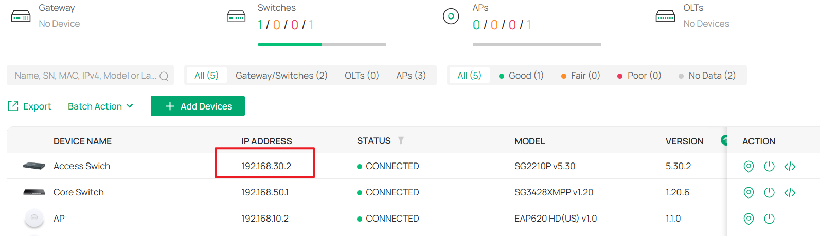
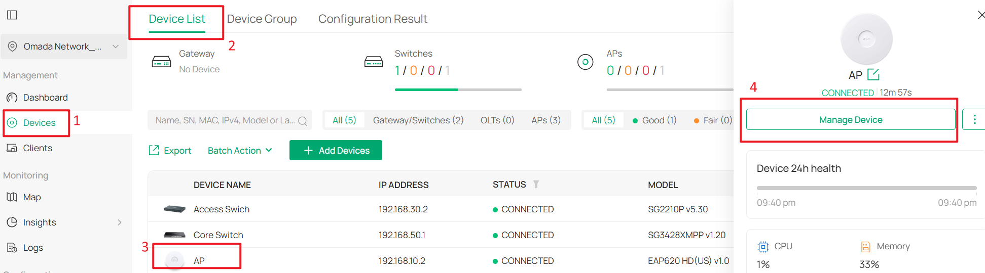
Step 5. Configure the AP Management VLAN
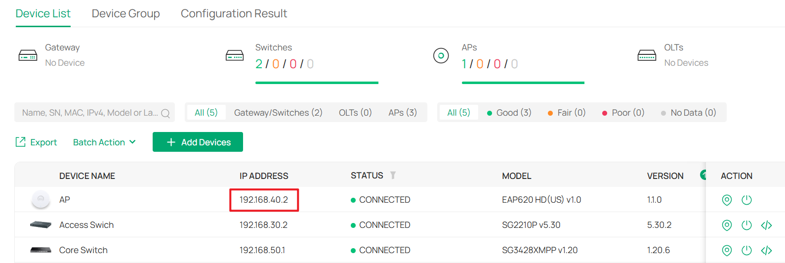
Go to Devices > Device List, click an AP and Manage Device to enter its private configuration page, then go to Config > General.
Change Management VLAN to Custom, and set LAN Network to AP MGMT.
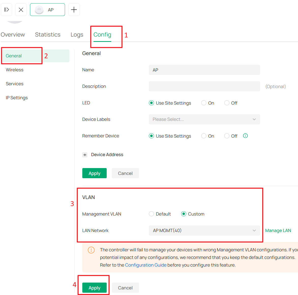
Wait a moment for the configuration to take effect. Once completed, you will find that the AP’s IP address has changed.
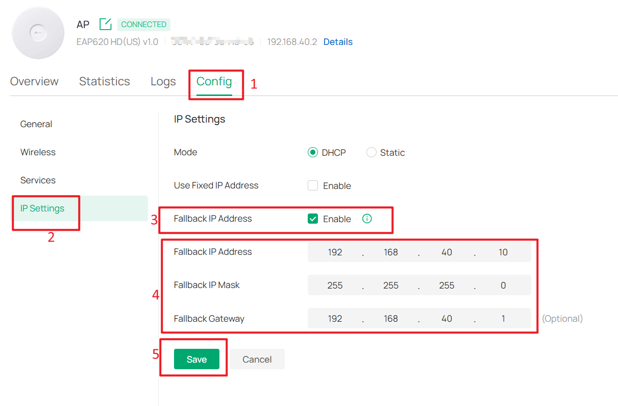
Optionally, you can configure the Fallback IP and Fallback Gateway by go to Config > IP Settings. In this example, they are set to 192.168.40.10, 255.255.255.0, and 192.168.40.1.
Step 6. Configure Switch Ports for the Client Network.
To ensure that all wired clients can obtain IP addresses from the Client Network, we need to change the port VLAN configuration of all downlink ports on the switches that are directly connected to end devices.
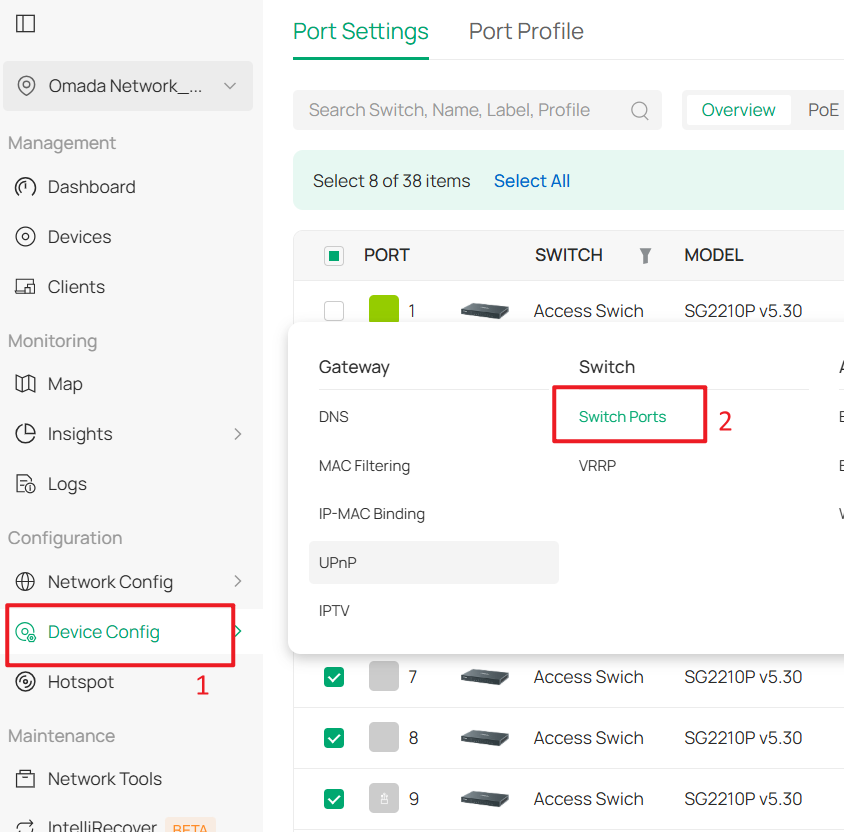
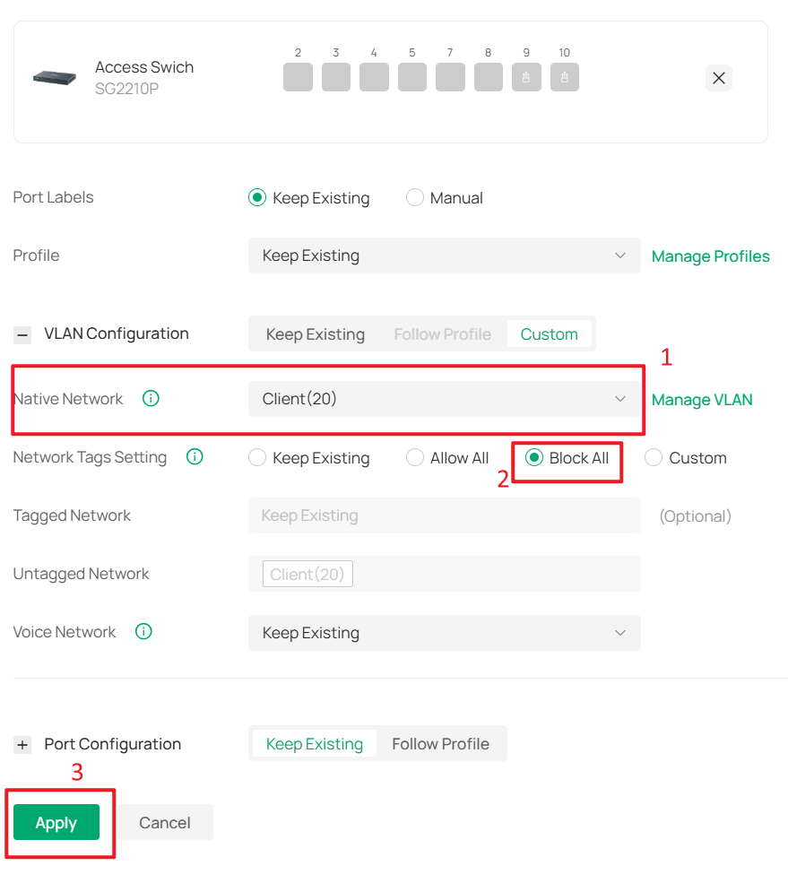
Go to Device Config > Switch > Switch Ports, select the downlink ports that are directly connected to client devices, and then click Edit Selected to batch modify their port profiles.
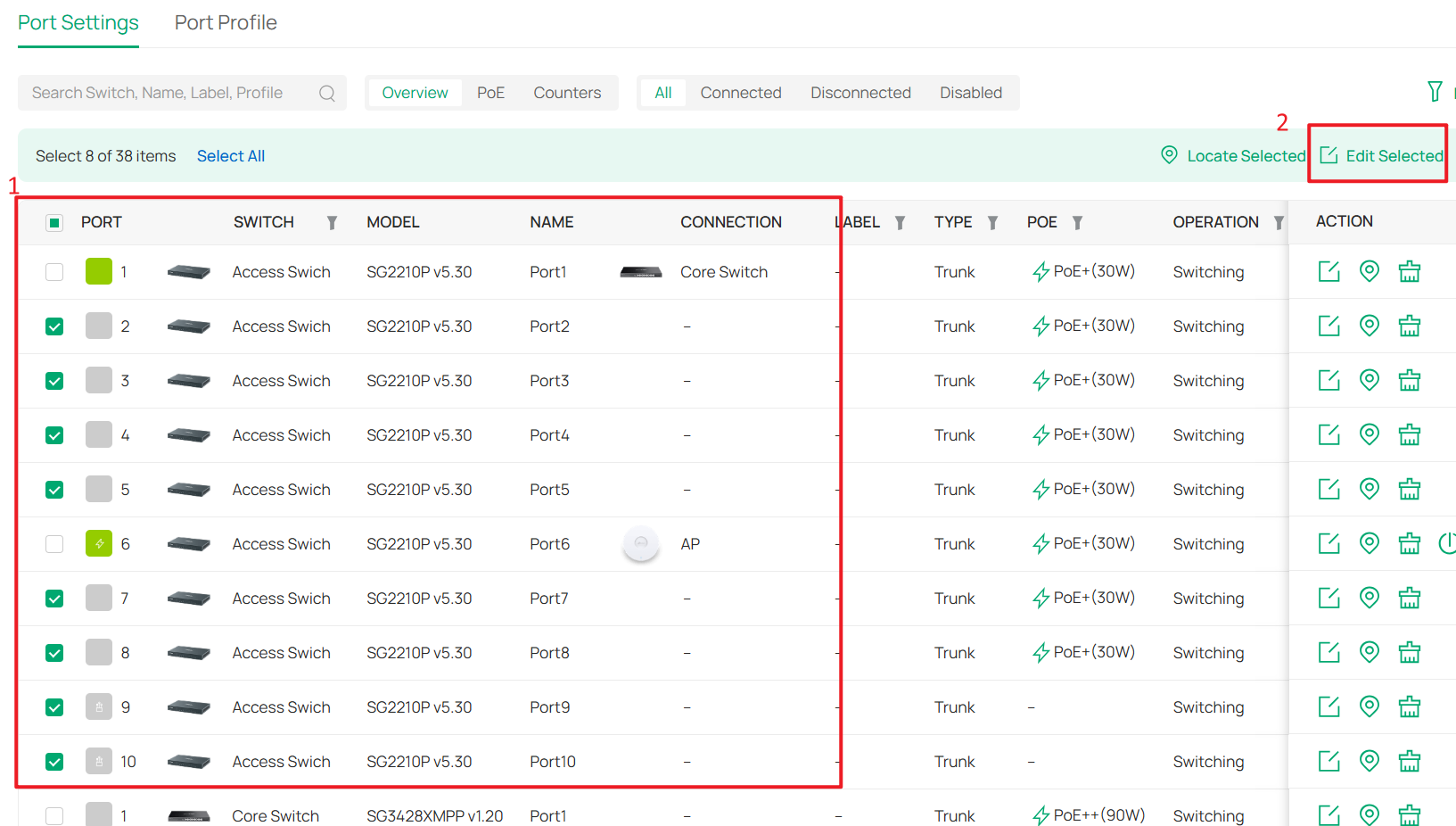
Change the Native Network of these ports to Client, set Network Tags Setting to Block All, and then click Apply to save the configuration.
Step 7. Configure the Client SSID
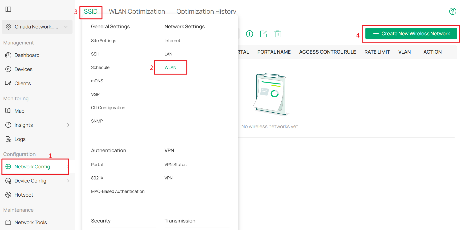
Go to Network Config > Network Settings > WLAN > SSID, and click +Create New Wireless Network.
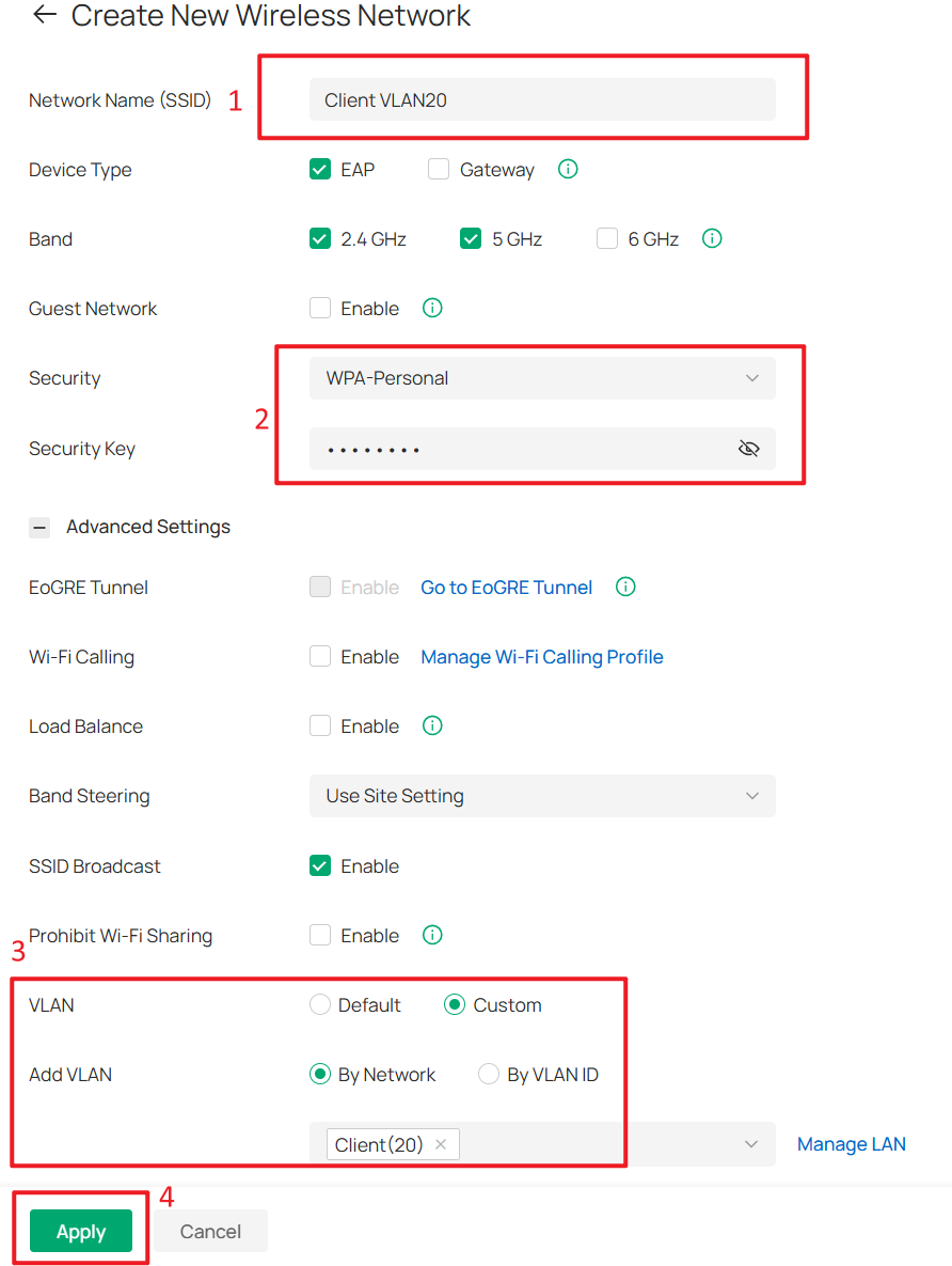
Set the SSID name and password, then expand Advanced Settings. Set VLAN to Custom, select By Network under Add VLAN, and choose the Client network that was created earlier.
Click Apply to save the configuration.
Step 8. Create IP Groups and ACL Rules for Client Isolation
Currently, some networks use the Core Switch as the DHCP server, so they cannot be selected as Network in Switch ACL rules. Therefore, we must first create IP Groups and then create ACL rules based on these IP Groups.
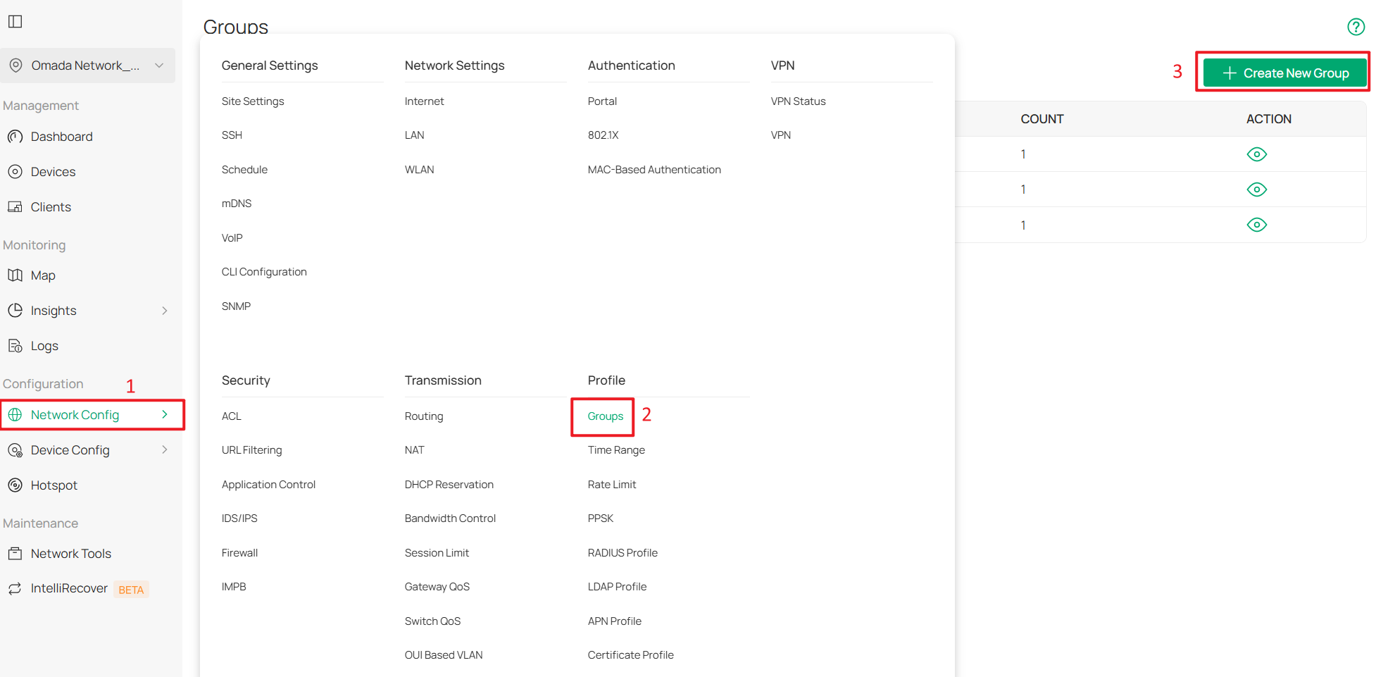
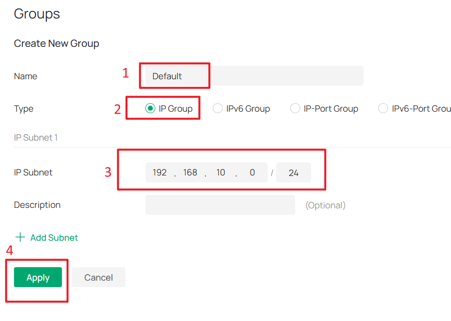
Go to Network Config > Profile > Groups, and click +Create New Group.
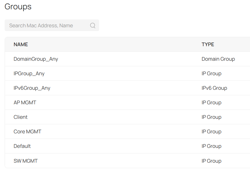
Create one IP Group for each subnet. In this example, there are five subnets: Default, Client, SW MGMT, AP MGMT, and Core MGMT.
Enter a group name, set the Type to IP Group, and enter the network address of each subnet in IP Subnet. For example, the IP subnet of the Default group is 192.168.10.0/24. Click Apply to save the configuration.
The final result should appear as shown below:
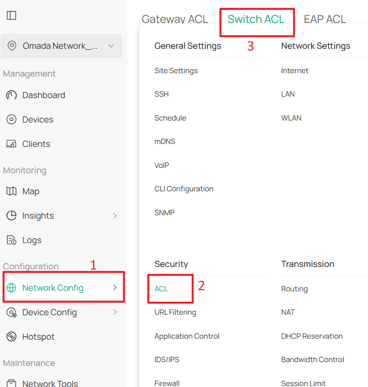
Next, go to Network Config > Security > ACL > Switch ACL, and click +Create New Rule to create a new ACL rule.
Enter a rule name as the Description, select Deny for Policy, and choose All for Protocol.
For both Source and Destination, set the type to IP Group. Select the Client group as the Source, and select all other management groups as the Destination. Click Create to apply the rule.
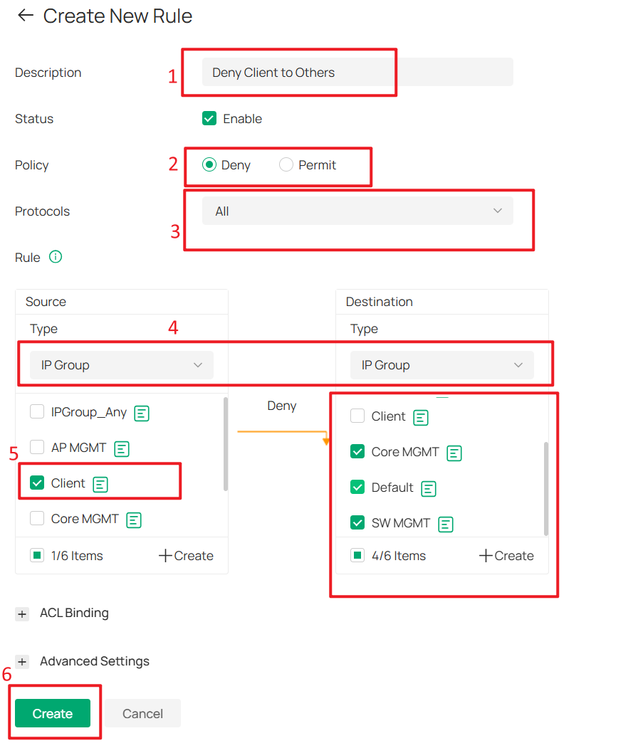
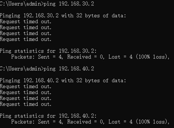
With this ACL rule in place, when client devices connect and obtain IP addresses from the 192.168.20.0/24 subnet, they will be unable to access the Omada Controller or other Omada devices, thereby enhancing overall network security.
Part 3. Configure Gateway Integration and Inter-VLAN Routing
Step 1. Adopt the Gateway into the Omada Controller (Optional)
If you have Omada gateway, then you can also adopt it on the Omada controller for better management. But here we have already switched the default VLAN ID to 10, while the gateway will have DHCP server enabled by default and set itself as 192.168.0.1, this will cause the gateway failed to be adopted, so we need to make some pre-configuration on the gateway before adopting on the Omada controller.
Access 192.168.0.1 to log in to the gateway’s Web UI. After initialization and setting the username and password, go to Network > LAN > LAN, and click Edit on the default network.
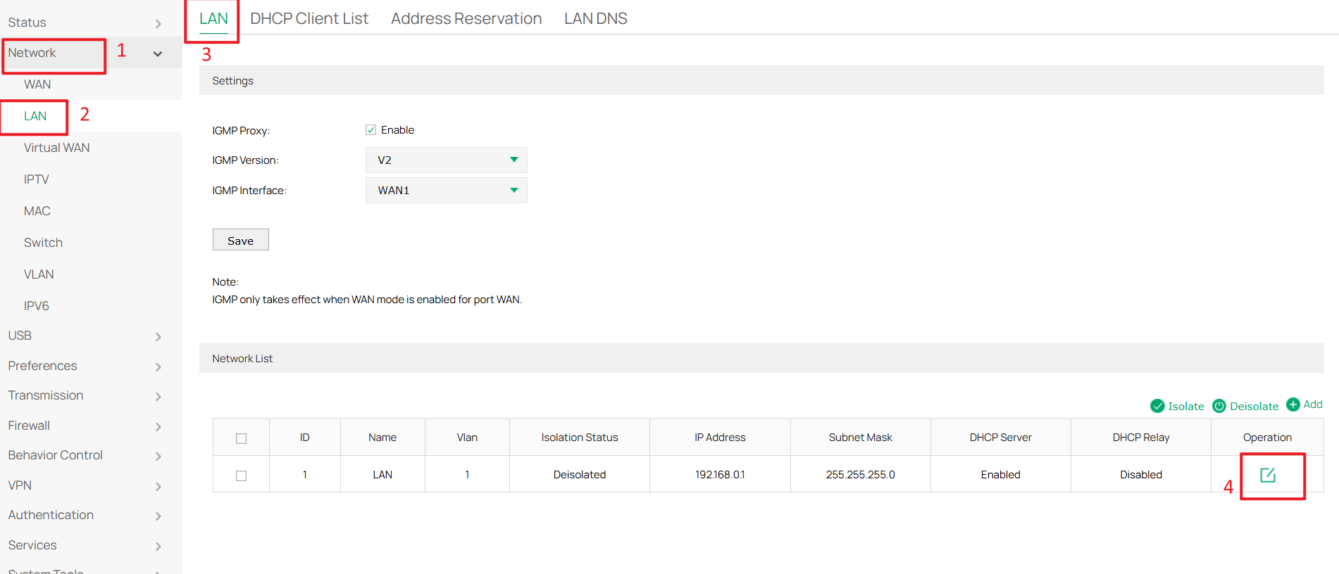
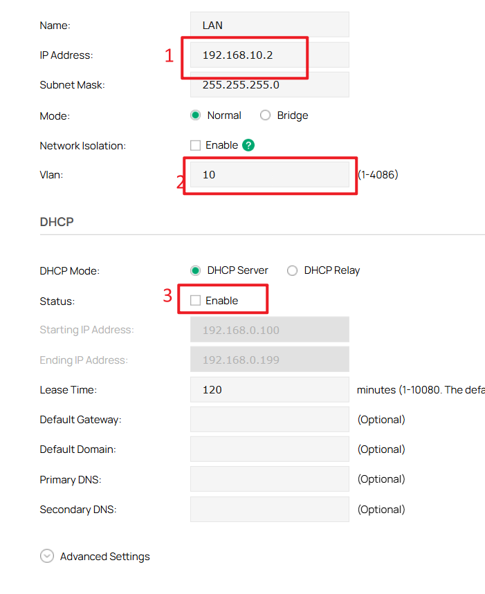
Change this network to VLAN 10 and modify the IP address to 192.168.10.x/24.
For example, in this case it is changed to 192.168.10.2. Since the DHCP server is already enabled on the Core Switch, disable the DHCP server on the gateway by unchecking Enable under Status in the DHCP section. Click OK to save the configuration.
After changing the gateway’s IP address, you also need to change your PC’s IP address to the 192.168.10.x/24 subnet (for example, 192.168.10.100) in order to access the gateway’s Web UI again.
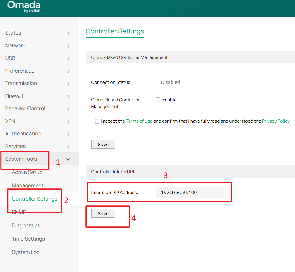
Go to System Tools > Controller Settings, enter the Controller’s IP address (192.168.50.100) in Inform URL/IP Address, and click Save.
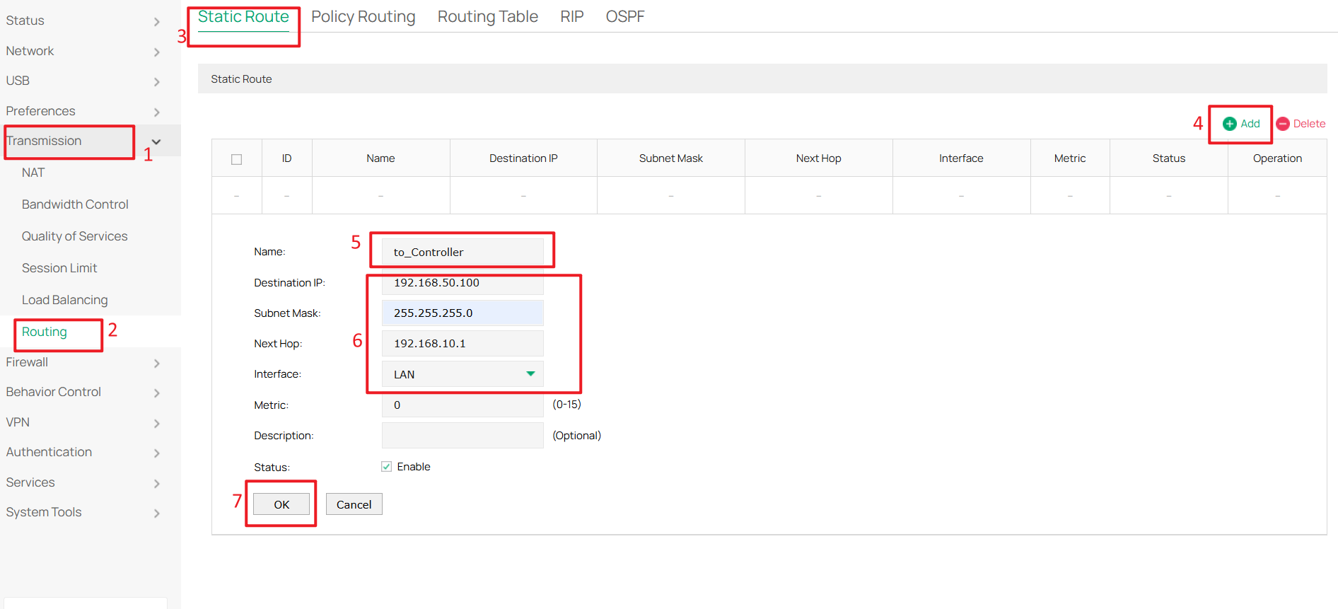
After configuring the Controller IP address, a static route is required so the gateway can reach the Controller. Go to Transmission > Routing > Static Route, then click Add to create a new static route.
Set Destination IP to the Controller’s IP address (192.168.50.100), and configure Next Hop as the Core Switch Default Network interface IP address (192.168.10.1). Select LAN for the interface, then click OK to create the route.
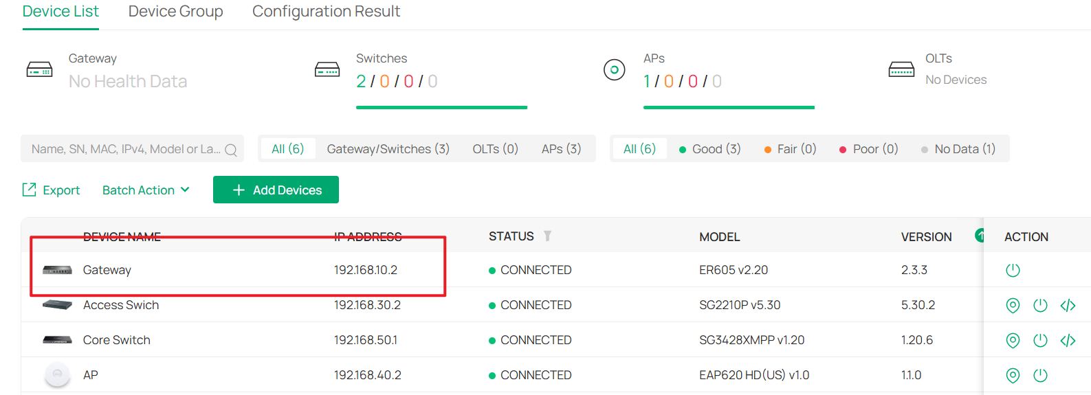
After completing the pre-configuration, connect the gateway to a Core Switch port whose Native Network is set to Default. You will see the gateway with IP address 192.168.10.2 in the device list. Use the username and password you configured to adopt it as a gateway.
Step 2. Configure static route on the Core Switch.
Regardless of whether you are using an Omada Gateway, you must configure static routes on the Core Switch and forward all Internet traffic to the gateway. This is because all Layer 3 forwarding is handled by the Core Switch, and the default gateway for each network is set to the Core Switch.
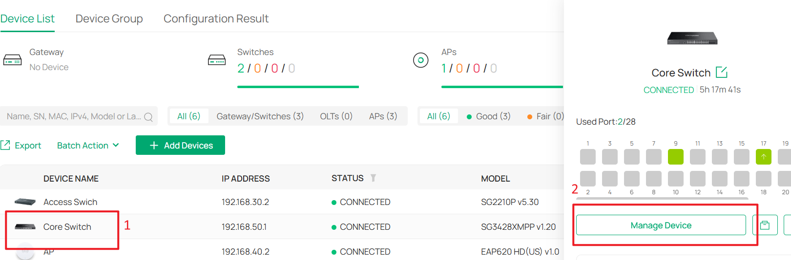
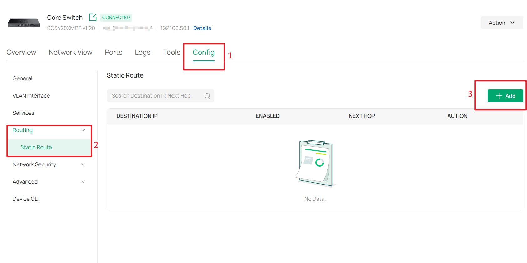
Go to Devices > Device List, click Core Switch and Manage Device to enter its private configuration page, then navigate to Config > Routing > Static Route. Click +Add to add a new static route.
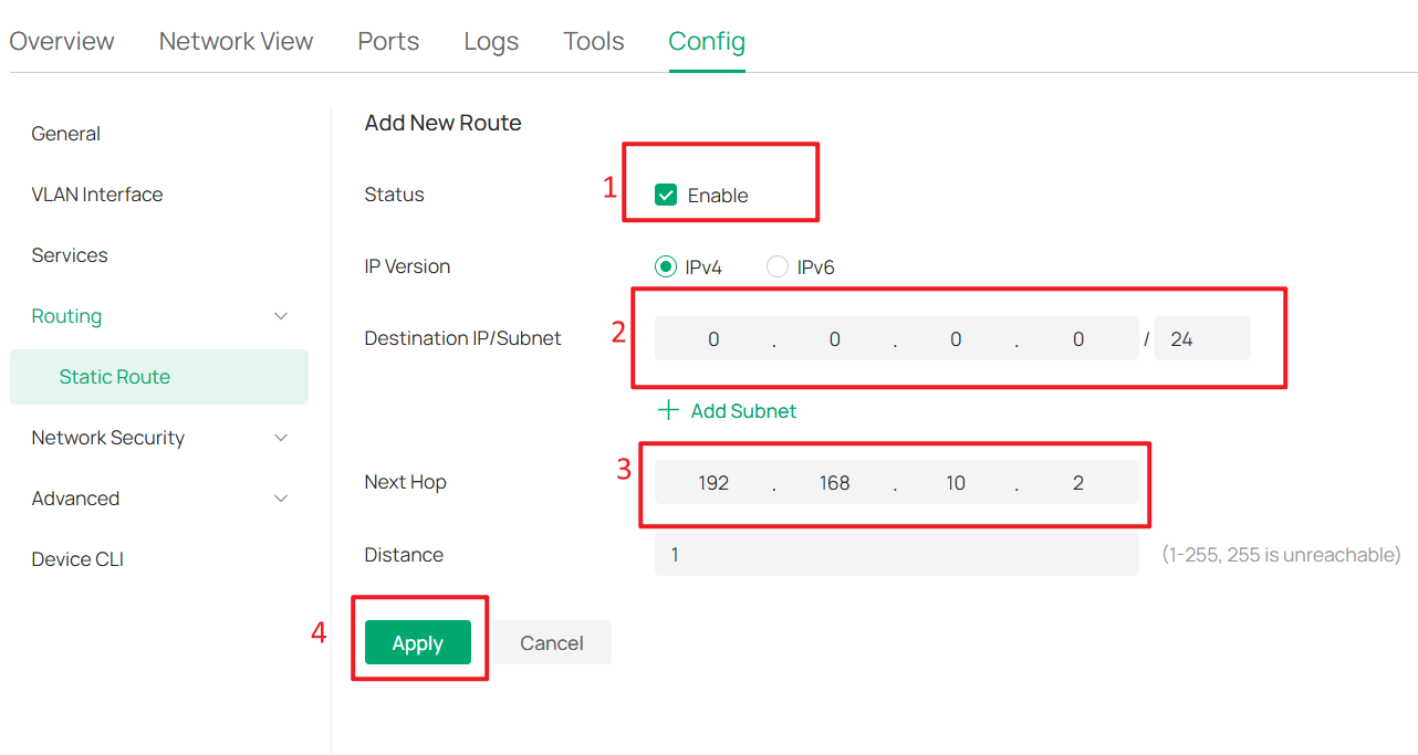
Enable the route by setting Status to Enable. Since this route is used for all Internet traffic, set Destination IP/Subnet to 0.0.0.0/0, and set Next Hop to the gateway IP address 192.168.10.2.
For other traffic, the system will always prefer more specific routes, so simply set the Distance to 1, then click Apply to save the configuration.
After configuring the static route on the Core Switch, reverse static routes must also be configured on the gateway to ensure that all traffic from the Internet is forwarded back to the Core Switch. On the Core Switch, the destination is set to 0.0.0.0/0 with a next hop of 192.168.10.2, so corresponding reverse routes are required on the gateway.
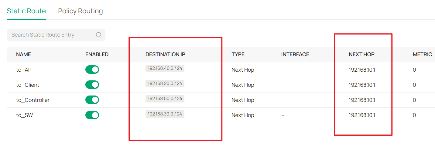
At this point, the subnets in the network are 192.168.10.0/24, 192.168.20.0/24, 192.168.30.0/24, 192.168.40.0/24, and 192.168.50.0/24. Since the gateway LAN IP belongs to 192.168.10.0/24, no manual route is required for this subnet. Therefore, four static routes are required, with the next hop set to 192.168.10.1, which is the Core Switch Default VLAN interface.
If you are not using an Omada Gateway, simply configure these static routes on your gateway. If you are using an Omada Gateway and it has already been adopted, follow next step to configure the static routes on the Omada Gateway via the Controller.
Step 3. Configure Static Routes on the Omada Gateway (Optional)
Go to Network Settings > Transmission > Routing > Static Route, then click Create New Route.
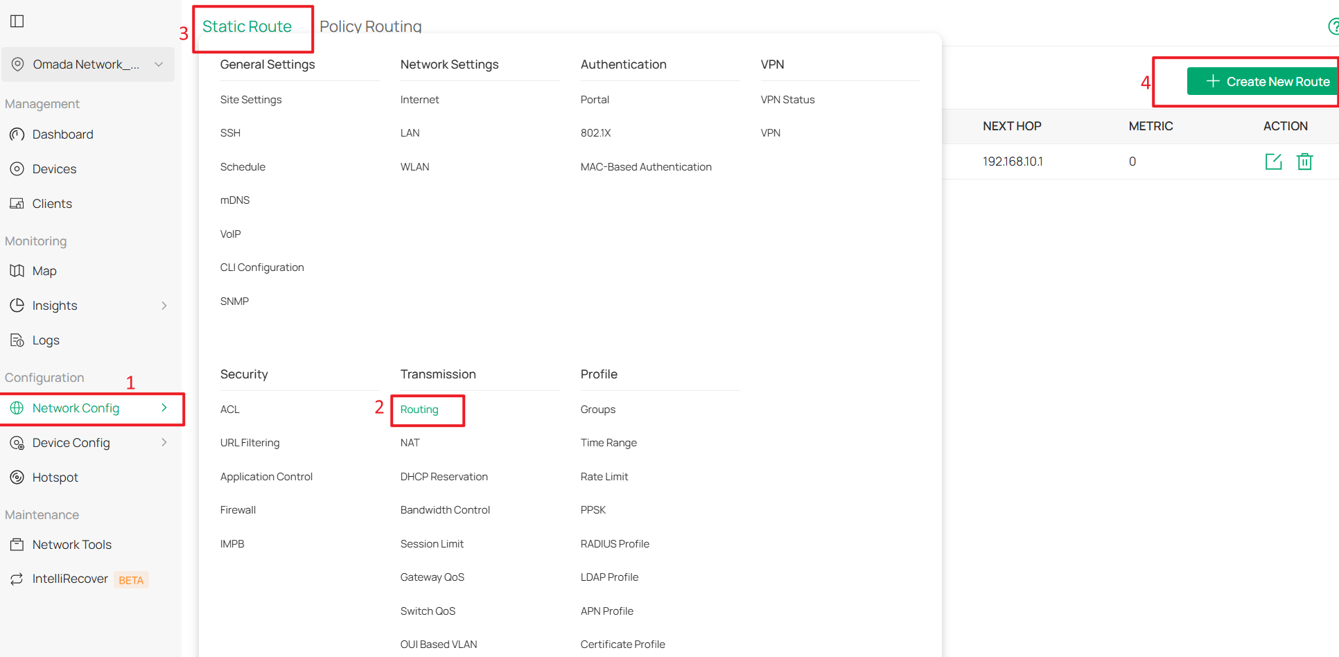
During the gateway pre-configuration, a static route for 192.168.50.0/24 has already been configured. Therefore, only three additional static routes are required.
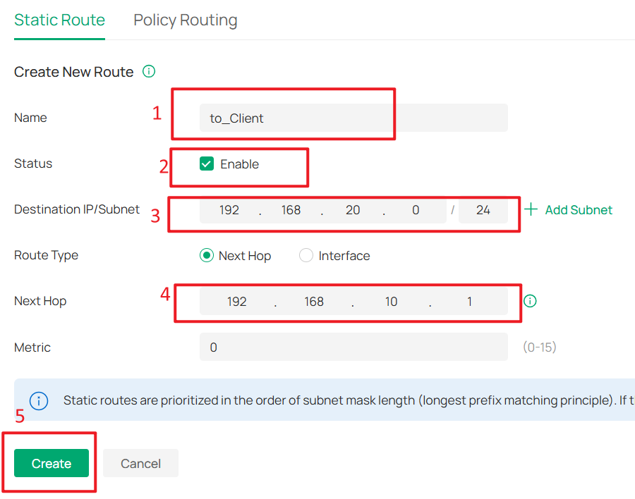
Set the Destination IP/Subnet of these routes to 192.168.20.0/24, 192.168.30.0/24, and 192.168.40.0/24, respectively. Set the route type to Next Hop, and configure the next hop address as the Core Switch Default Network interface IP address (192.168.10.1). Click Create to add each static route.
The final result should appear as shown below:
Step 4. Add Additional Switches and APs (Optional)
To add more switches and APs to the network, simply connect them to switch ports where the Native Network is set to Default and Network Tags Setting is set to Allow All.
They will then successfully obtain IP addresses from the Default Network (192.168.10.0/24). After they are adopted, follow the previous steps to change their Management VLAN.
Verification
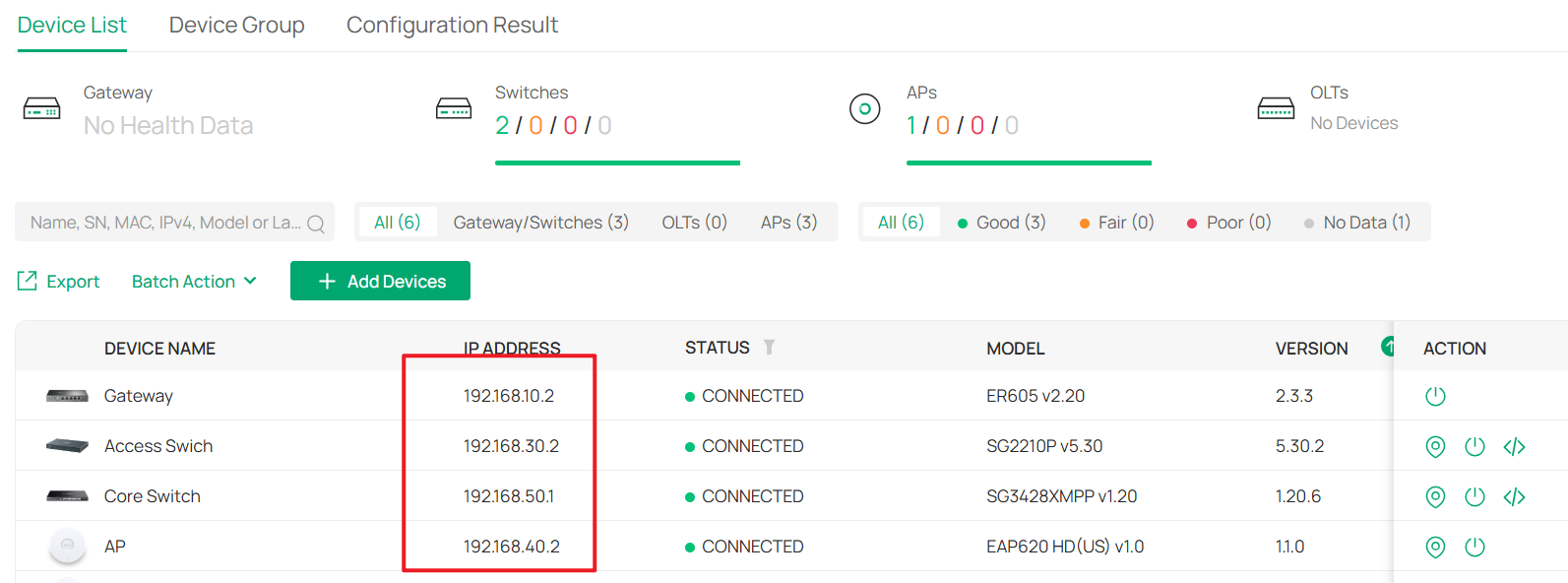
After this configuration, the gateway, switches and APs are in different management Networks.
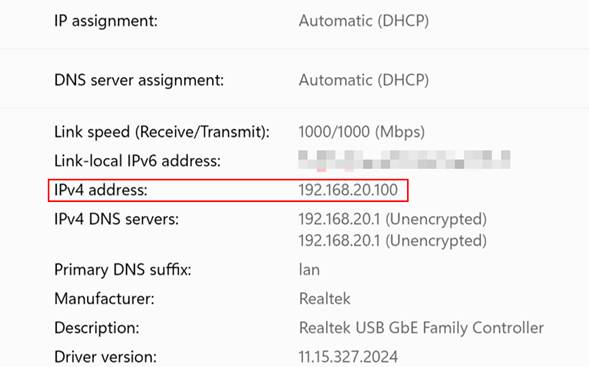
The wired PC connected on the switch is obtaining IP address from the clients VLAN 192.168.20.0/24:
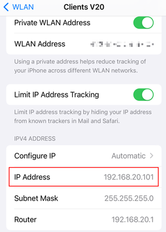
The phone connected wirelessly is obtaining IP address from clients VLAN 192.168.20.0/24:
The client is unable to access managed network devices, while Internet connectivity remains normal.
Conclusion
This guide demonstrated how to deploy a business network using dedicated management VLANs for the gateway, core switch, switches, and APs, while placing wired and wireless clients in a separate client VLAN to isolate them from the management network.
It also explained how to add new devices to an existing network and integrate either an Omada gateway or a third-party gateway into the deployment.
To learn more about each function and configuration, please visit Support Home to download or check the manual for your product.
