


Contents
Introduction
Before Omada Controller V6, when adopting a switch on controller, the default configuration will be applied to the switch and override all the previous pre-configuration done in standalone mode. This could cause inconvenience while adopting switches to a network which management VLAN is not the default VLAN. If the default configuration, especially the default VLAN interface, overrides the pre-configuration done on the switch, it will be disconnected after adoption and hard to recover.
Starting from Omada Network V6, if you are using the switch firmware compatible with Omada Network V6, the following pre-configuration will be kept after adoption, enhancing the adoption experience in a running network:
- Management VLAN and Interface
- Static IP of the Interface
- Static routes
- Native VLAN on the port
- Port speed
- Link Aggregation Group (LAG) settings
Requirements
- Omada Controller V6 and above
- Omada Switches (Excluding Omada Agile Switches) with the latest firmware
Configuration
The content below provides an example of how the pre-configurations listed above are maintained after adoption. In this example, VLAN 200 and its interface will be created and set the static IP address as 192.168.200.100, then set this VLAN as the management VLAN; the controller is within the same subnet of VLAN 200, so the switch can only communicate with the controller via VLAN 200.
Pre-configuration on the Switch in Standalone Mode
Configure the management VLAN and interface (non-default VLAN), static IP address on the interface, static route, LAG, and change the native VLAN on ports as well as port speed.
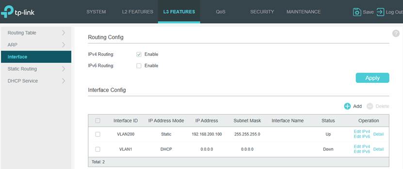
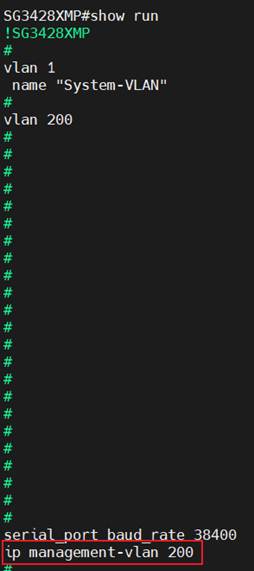
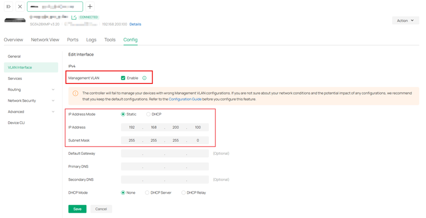
Step 1. Create a new VLAN as well as its VLAN interface, set up a static IP for it, and set this VLAN as the management VLAN.
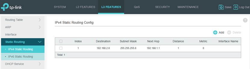
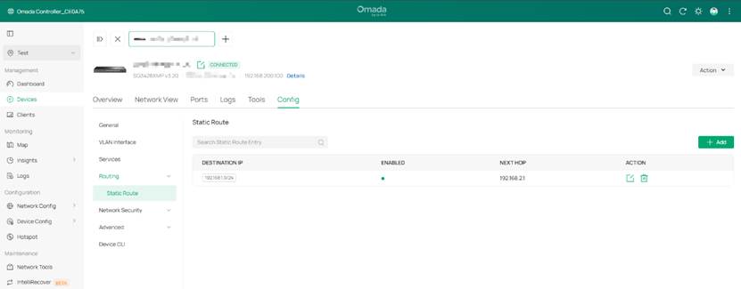
Step 2. Configure static routes.
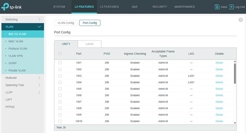
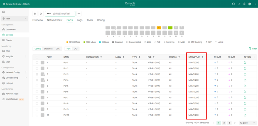
Step 3. Configure the Port’s native VLANs. In this example, set the PVID on the ports as 200 and set VLAN 200 as untagged on the ports.
Note: Currently, to maintain a port related settings after adopted, the management VLAN must set as the native VLAN on this port, which means that to set the management VLAN ID as PVID for this port and set the management VLAN as untagged on this port. This rule also applies to LAG ports, to keep the settings, user need to apply the configuration mentioned above to the LAG ports additionally, applying to LAG member ports only doesn’t take effect. For the port not meeting the requirements above, its settings will not be maintained after adoption. 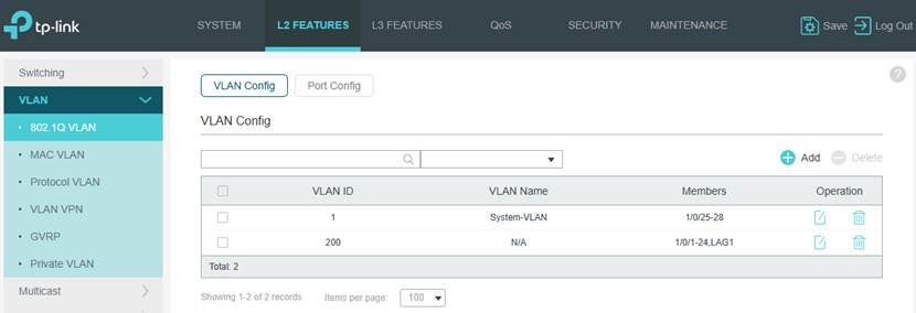
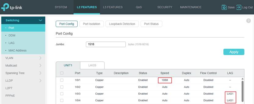
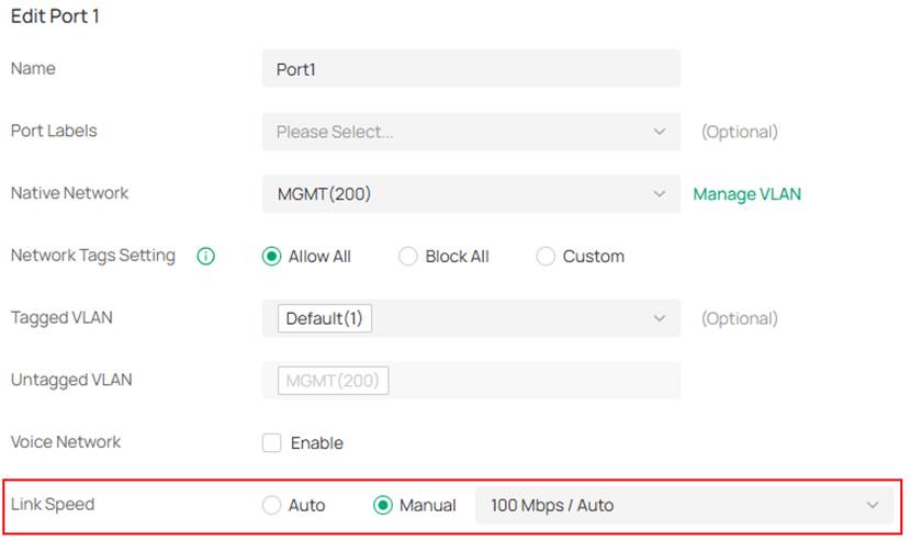
Step 4. Configure port speed and LAG. In this example, port 1’s speed was changed to 100Mbps and port 3 and 4 were configured as LAG 1.
Make Configuration on the Controller and Adopt the Switch
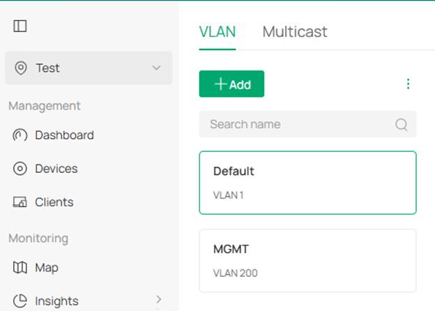
To maintain VLAN 200 and its network after adopting the switch, VLAN 200 itself must be created on the controller first.
Step 1. Create the corresponding VLANs on the controller, in this example, VLAN 200 needs to be created.
Step 2. On the controller, the switch should be shown as pending with the IP address in VLAN 200 network, click the Adopt button to adopt the switch. 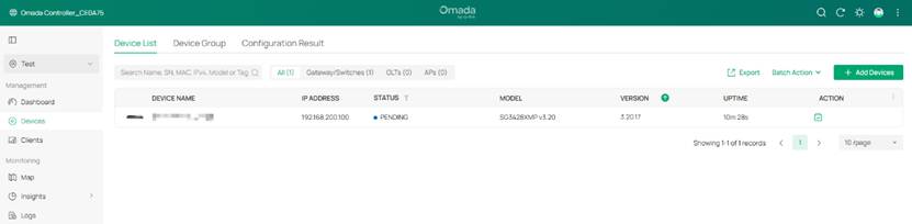
Verification
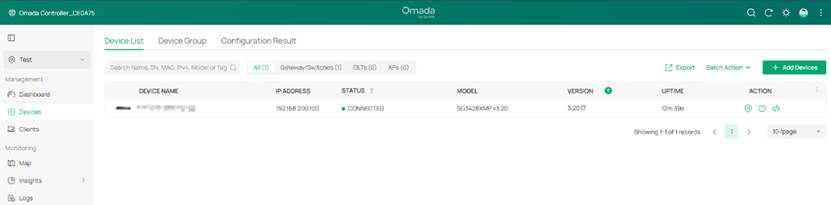
The switch should be successfully adopted and stay in connected status after adopted, together with its IP address in the VLAN 200 network. This indicates that the non-default management VLAN and the static IP address on the interface were maintained.
Check the device detailed info page, the related configurations should be the same as before.
- Management VLAN and Static IP of the Interface
- Static routes
- Native VLAN on the port
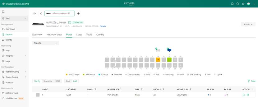
- Port speed
- LAG status
Conclusion
In this article, we have introduced which pre-configurations could be maintained after being adopted on the latest controller V6 and latest switch firmware. A brief example was also carried out for validation.
Get to know more details of each function and configuration please go to Download Center to download the manual of your product.
