


Contents
MPLS LDP Configuration Example
Configuration of LDP-based VPLS
Configuration of LDP-based H-VPLS
Introduction
In modern enterprise networks, organizations typically operate multiple geographically distributed sites, including headquarters, branch offices, and data centers. These sites require reliable connectivity to support access to internal applications, data exchange, and consistent business operations. For example, branch office users often need seamless access to centralized resources, such as ERP systems or file servers hosted at the headquarters. To enable efficient interconnection across dispersed locations, service providers deliver Layer 2 VPN (L2VPN) services that provide transparent connectivity, allowing remote sites to function as if they are part of the same local network.
To implement these services efficiently, MPLS (Multi‑Protocol Label Switching) is widely adopted as the underlying transport technology. MPLS improves forwarding performance and scalability by using label-based switching instead of traditional IP routing lookups. Based on MPLS, service providers can build Layer 2 VPN services that seamlessly transport Ethernet traffic over a wide area network while abstracting the underlying network complexity from end users.
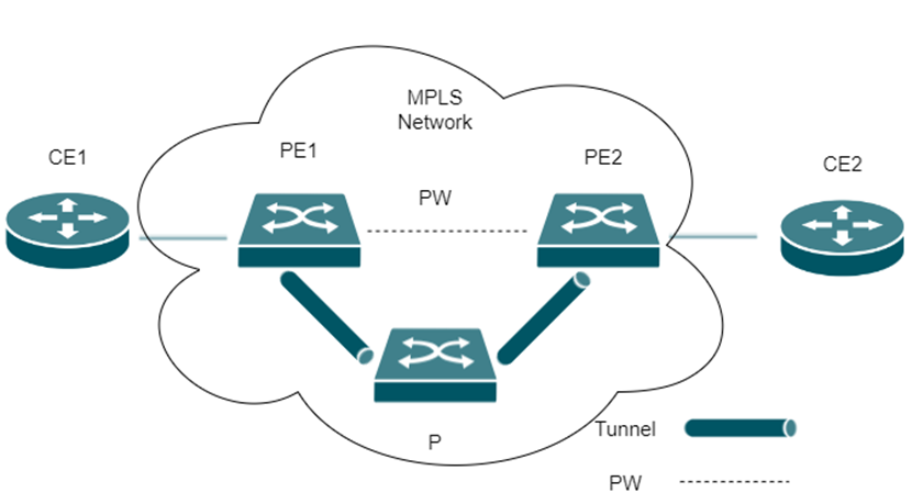
VPWS (Virtual Private Wire Service) is one of the key MPLS Layer 2 VPN technologies. It provides a point‑to‑point connection between two customer sites by emulating a dedicated physical link, often referred to as a “virtual circuit.” With VPWS, data is forwarded directly between the two endpoints without performing MAC address learning or broadcast replication. This makes it a simple and efficient solution for scenarios that require secure and stable communication between two locations, such as connecting a headquarters to a data center or linking two critical business systems.
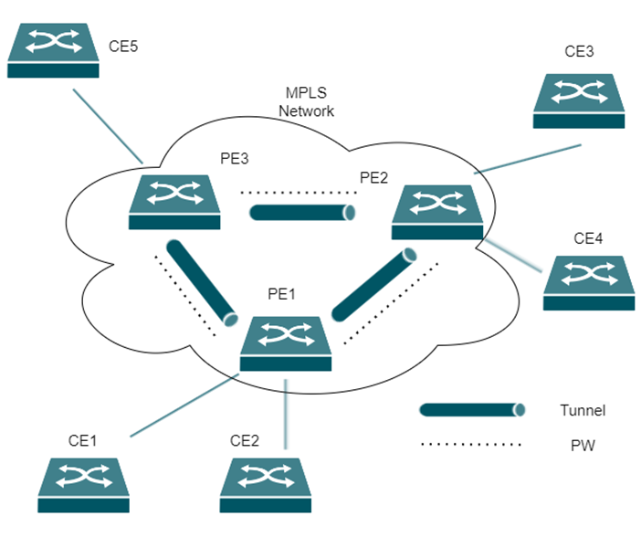
VPLS (Virtual Private LAN Service), on the other hand, extends this concept to multipoint connectivity. It allows multiple sites to be interconnected as if they are part of the same Ethernet LAN. In a VPLS network, provider edge devices emulate a virtual Layer 2 switch, enabling all connected sites to communicate with each other transparently. VPLS supports MAC address learning and broadcast forwarding, making it suitable for enterprise environments that require full mesh communication between multiple branches. Compared to VPWS, VPLS offers greater flexibility for multi‑site deployments, while still leveraging MPLS for efficient and scalable transport.
As illustrated, the entire VPLS network behaves like a single virtual switch. It establishes virtual links—also known as pseudowires (PWs)—between different sites within each VPN over MPLS tunnels. Through these PWs, Layer 2 user traffic is transparently forwarded between sites.
For Provider Edge (PE) devices, they learn source MAC addresses while forwarding packets and build MAC forwarding table entries accordingly. This process creates a mapping between MAC addresses, the user-facing Access Circuits (ACs), and the corresponding pseudowires (PWs), enabling correct traffic forwarding across the VPLS network.
Requirements
- Omada Campus switches (firmware version 1.20.1 or above)
MPLS LDP Configuration
MPLS LDP is a protocol that establishes Label switching path(LSP), enabling the network to transmit data efficiently and providing the foundation for services such as VPWS and VPLS.
MPLS LDP CLI Commands
The following table lists commonly used CLI commands for MPLS and MPLS LDP configuration, including their functions for setup, control, and troubleshooting.
|
No. |
CLI Command |
Function |
|
1 |
mpls |
Enables MPLS globally and on interfaces |
|
2 |
mpls ldp |
Enables LDP globally and on interfaces |
|
3 |
lsr-id |
Configures the LSR ID (Router ID) of the device (in LDP view) |
|
4 |
transport-address |
Configures the transport address for LDP sessions (in LDP view) |
|
5 |
targeted-peer <ip-address> |
Configures targeted LDP peers for L2VPN services such as VPWS and VPLS (in LDP view) |
|
6 |
explicit-null |
Enables explicit NULL label configuration (in LDP view) |
|
7 |
label control-mode {independent | ordered} |
Configures the LDP label distribution control mode (in LDP view) |
|
8 |
pwe3 |
Enables PWE3 signaling capability and allows dynamic VPWS to carry control information (in LDP view) |
|
9 |
timer hello hold |
Configures LDP Hello hold time (in LDP view) |
|
10 |
timer hello interval |
Configures Hello transmission interval (in LDP view) |
|
11 |
timer keepalive hold |
Configures Keepalive hold time (in LDP view) |
|
12 |
timer keepalive interval |
Configures Keepalive transmission interval (in LDP view) |
|
13 |
timer targeted-hello hold |
Configures targeted Hello hold time (in LDP view) |
|
14 |
timer targeted-hello interval |
Configures targeted Hello transmission interval (in LDP view) |
|
15 |
mpls ldp timer hello hold |
Configures Hello hold time on interfaces |
|
16 |
mpls ldp timer hello interval |
Configures Hello interval on interfaces |
|
17 |
mpls ldp timer keepalive hold |
Configures Keepalive hold time on interfaces |
|
18 |
mpls ldp timer keepalive interval |
Configures Keepalive interval on interfaces |
|
19 |
show mpls adapter |
Displays MPLS hardware adapter information |
|
20 |
show mpls ftn |
Displays MPLS Forwarding Table (FTN) information |
|
21 |
show mpls ldp adjacency |
Shows LDP adjacency relationships |
|
22 |
show mpls ldp downstream |
Displays downstream LDP information |
|
23 |
debug mpls ldp |
Enables LDP debugging |
|
24 |
show mpls ldp debug |
Displays LDP debug information |
|
25 |
show mpls ldp fec |
Displays LDP FEC mappings |
|
26 |
show mpls ldp instance |
Displays LDP instance information |
|
27 |
show mpls ldp interface |
Displays LDP interface status |
|
28 |
show mpls ldp global |
Displays global LDP status and information |
|
29 |
show mpls ldp route |
Displays LDP routing information |
|
30 |
show mpls ldp session |
Displays detailed LDP session information |
|
31 |
show mpls ldp upstream |
Displays upstream LDP information |
|
32 |
show mpls ilm |
Displays Incoming Label Map (ILM) information |
|
33 |
show mpls static-lsp |
Displays static LSP information (used in static MPLS or hybrid scenarios) |
|
34 |
show mpls ldp vc |
Displays LDP-based VPWS virtual circuit information |
|
35 |
show mpls ldp vpls |
Displays LDP-based VPLS information |
Note:
No 6: Label 0 (Explicit NULL) means that the egress (last-hop) device keeps the MPLS label (0 for IPv4) so that it can apply QoS or special handling, instead of removing the label before forwarding the packet.
No 33: Static LSPs represent the static implementation mode of LDP, and they are also supported in our system. Different deployment combinations are supported, including static L2VPN over static MPLS, static L2VPN over LDP, and dynamic L2VPN over LDP.
MPLS LDP Configuration Example
Before configuring LDP, it is necessary to ensure network-layer connectivity between all nodes by configuring static routes or an IGP such as OSPF. After the configuration is completed, an LDP session is established, enabling communication between sites through LDP-based label switching.
The configuration typically involves assigning IP addresses to all interfaces, setting up Loopback addresses as LSR IDs, and advertising these routes through OSPF. Then MPLS and MPLS LDP are enabled globally on all devices, with the LSR ID and transport address configured accordingly. MPLS and LDP must also be enabled on the relevant interfaces. Finally, CE devices are configured with appropriate interface routing, completing the setup and allowing end-to-end connectivity across the network.
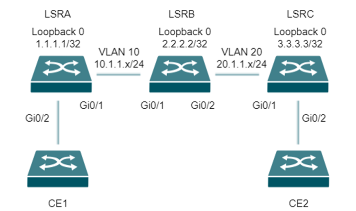
Step 1. LSR A Configuration
CLI:
#
mpls
mpls ldp
lsr-id 1.1.1.1
transport-address 1.1.1.1
#
interface loopback 1
ip address 1.1.1.1 255.255.255.255
#
interface vlan 10
ip address 10.1.1.1 255.255.255.0
mpls
mpls ldp
#
interface gigabitEthernet 1/0/1
switchport general allow vlan 10 tagged
#
interface gigabitEthernet 1/0/2
no switchport
ip address 100.1.1.1 255.255.255.0
#
router ospf 1
network 10.1.1.0 255.255.255.0 area 0
network 1.1.1.1 255.255.255.255 area 0
Step 2. LSR B Configuration
CLI:
#
mpls
mpls ldp
lsr-id 2.2.2.2
transport-address 2.2.2.2
#
#
interface vlan 10
ip address 10.1.1.2 255.255.255.0
mpls
mpls ldp
#
interface vlan 20
ip address 20.1.1.1 255.255.255.0
mpls
mpls ldp
#
interface loopback 1
ip address 2.2.2.2 255.255.255.255
#
interface gigabitEthernet 1/0/1
switchport general allow vlan 10 tagged
#
interface gigabitEthernet 1/0/2
switchport general allow vlan 20 tagged
#
router ospf 1
network 10.1.1.0 255.255.255.0 area 0
network 20.1.1.0 255.255.255.0 area 0
network 2.2.2.2 255.255.255.255 area 0
Step 3. LSR C Configuration
CLI:
#
mpls
mpls ldp
lsr-id 3.3.3.3
transport-address 3.3.3.3
#
interface loopback 1
ip address 3.3.3.3 255.255.255.255
#
interface vlan 20
ip address 20.1.1.2 255.255.255.0
mpls
mpls ldp
#
interface gigabitEthernet 1/0/1
switchport general allow vlan 20 tagged
#
interface gigabitEthernet 1/0/2
no switchport
ip address 200.1.1.1 255.255.255.0
#
router ospf 1
network 20.1.1.0 255.255.255.0 area 0
network 3.3.3.3 255.255.255.255 area 0
VPWS Configuration
VPWS CLI Commands
The following are commonly used CLI commands for VPWS.
|
No. |
Function |
Description |
CLI Commands |
|
1 |
Establish LDP peer for VPWS connection |
Establish LDP targeted peers. VPWS connections rely on LDP targeted sessions between PE devices. |
targeted-peer <ip-address> |
|
2 |
Enable MPLS L2VPN |
Enable L2VPN globally. This command applies to both dynamic (LDP-based) and static L2VPN services. |
mpls l2vpn |
|
3 |
Establish VPWS connection |
Create a Virtual Circuit (VC) between PE devices. If labels are not configured, dynamic LDP signaling is used; otherwise, static VPWS is established. |
xconnect vc-id peer <peer-ip> [in-label <in> out-label <out>] {raw | tagged} |
|
4 |
Tear down VPWS connection |
Remove the VPWS connection by deleting the configured VC. |
no xconnect |
|
5 |
View VPWS connection status |
Display configuration and operational status of VC connections for monitoring and troubleshooting. |
show mpls vc [detail] |
Note: VPWS is a point-to-point connection. When a VLAN interface is used as the AC interface, only one Layer 2 physical port should be configured in the VLAN. If no physical port exists in the VLAN, the VPWS connection cannot be established. If multiple physical ports are configured in the VLAN, only one port forwards traffic, which may lead to unintended behavior.
VPWS Configuration Example
Before you start configuring LDP-based VPWS, ensure that all nodes can reach each other at the network layer by setting up static routes or using an IGP such as IS-IS. After you complete the configuration, the system establishes a VPWS Layer 2 VPN tunnel, which allows you to achieve reliable point‑to‑point communication between sites.
To configure VPWS, assign IP addresses to all interfaces and configure Loopback addresses as LSR IDs, then advertise these routes using IS-IS.
Next, enable MPLS and MPLS LDP globally and configure the LSR ID, transport address, and targeted peers. You also need to enable MPLS and LDP on the relevant interfaces. After that, enable MPLS L2VPN on the PE devices, create the LDP-based VPWS connections, and finally configure routing on CE devices to complete the setup.
If LDP is not required, or if intermediate nodes in the service provider network do not support LDP, you can deploy static VPWS or VPLS instead. In this case, you need to manually configure labels between PE devices, and the VPN service does not rely on LDP signaling. This approach is suitable for scenarios where dynamic signaling is unavailable or restricted.
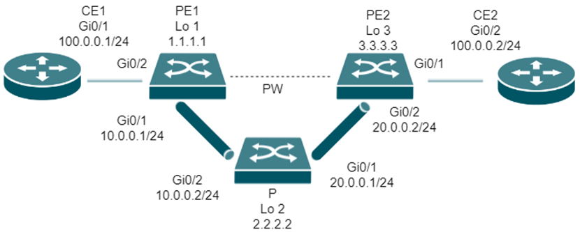
Step 1. PE1 Configuration
CLI:
router isis 100
net 00.0001.0000.0000.1111.00
#
mpls
mpls ldp
lsr-id 1.1.1.1
transport-address 1.1.1.1
targeted-peer 3.3.3.3
exit-targeted-peer
#
mpls l2vpn
#
interface vlan 1
ip address-alloc dhcp
#
interface loopback 1
ip address 1.1.1.1 255.255.255.255
ip router isis 100
#
interface gigabitEthernet 1/0/1
no switchport
ip address 10.0.0.1 255.255.255.0
ip router isis 100
mpls
mpls ldp
#
interface gigabitEthernet 1/0/2
no switchport
no ip address
xconnect 23 peer 3.3.3.3 raw
Step 2. P Configuration
CLI:
router isis 100
net 00.0001.0000.0000.1112.00
#
mpls
mpls ldp
lsr-id 2.2.2.2
transport-address 2.2.2.2
#
interface loopback 2
ip address 2.2.2.2 255.255.255.255
ip router isis 100
#
interface gigabitEthernet 1/0/1
no switchport
ip address 20.0.0.1 255.255.255.0
ip router isis 100
mpls
mpls ldp
#
interface gigabitEthernet 1/0/2
no switchport
ip address 10.0.0.2 255.255.255.0
ip router isis 100
mpls
mpls ldp
Step 3. PE2 Configuration
CLI:
router isis 100
net 00.0001.0000.0000.1113.00
#
mpls
mpls ldp
lsr-id 3.3.3.3
transport-address 3.3.3.3
targeted-peer 1.1.1.1
exit-targeted-peer
#
mpls l2vpn
#
interface vlan 1
ip address-alloc dhcp
#
interface loopback 3
ip address 3.3.3.3 255.255.255.255
ip router isis 100
#
interface gigabitEthernet 1/0/1
no switchport
no ip address
xconnect 23 peer 1.1.1.1 raw
#
interface gigabitEthernet 1/0/2
no switchport
ip address 20.0.0.2 255.255.255.0
ip router isis 100
mpls
mpls ldp
VPLS Configuration
VPLS CLI Commands
The following are commonly used CLI commands for VPLS.
|
No. |
Function |
Description |
CLI |
|
1 |
Enable MPLS and LDP |
Enable MPLS and LDP globally to prepare the transport network. |
mpls |
|
2 |
Establish LDP peer for VPLS |
Establish LDP targeted peers. VPLS (LDP‑based) relies on targeted LDP sessions between PE devices. |
targeted-peer <peer-ip> |
|
3 |
Enable MPLS L2VPN |
Enable MPLS L2VPN globally. This command applies to both static and dynamic VPLS services. |
mpls l2vpn |
|
4 |
Create VSI |
Create a VSI instance to define the VPLS service. |
vsi <vpls-name> vsi-id <vpls-id> |
|
5 |
Configure signaling |
Configure the signaling protocol for the VSI (dynamic or static). |
signaling {static | ldp} |
|
6 |
Configure encapsulation |
Set the encapsulation type for Layer 2 frames (default is tagged). |
encapsulation {tagged | raw} |
|
7 |
Configure peers |
Configure VPLS peers to establish connectivity between PE devices. |
peer <peer-ip> [in-label <in> out-label <out>] [encapsulation raw/tagged] [spoke] |
|
8 |
Enable/disable VSI |
Enable or disable the VSI instance as needed (optional). |
shutdown |
|
9 |
Bind interfaces |
Bind AC interfaces to the VSI to connect user traffic to the VPLS network. |
l2vpn-binding vsi <vpls-name> |
|
10 |
Verify status |
Verify and monitor VPLS configuration and operational status. |
show vpls |
Note:
Step 7:
This step applies to LDP-based VPLS, where you only need to configure the peer IP address. Static VPLS is not covered in this section and requires additional label configuration. The spoke option is used only in H‑VPLS and is not applicable to standard VPLS.
Step 8:
This step is optional. The VSI is enabled by default. You only need to use these commands when you want to disable or re-enable the service during maintenance or troubleshooting.
Configuration of LDP-based VPLS
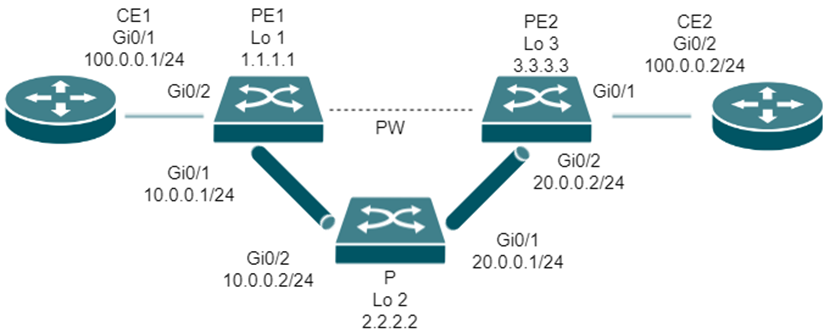
The configuration of VPLS generally follows a structured approach and can be implemented in two modes: dynamic (LDP-based) and static. First, the underlay network must be established by ensuring IP connectivity between all nodes using static routes or an IGP such as IS-IS. Then, MPLS is enabled in the network to provide transport capabilities.
For dynamic VPLS, MPLS LDP is also enabled so that PE devices can automatically establish label-switched paths (LSPs) and exchange signaling information. On PE devices, MPLS L2VPN is enabled, and a VSI (Virtual Switching Instance) is created to represent the VPLS service. LDP-based peers are then configured between PE devices to build the VPLS service dynamically. After that, interfaces on the private network side (ACs) are bound to the VSI to provide connectivity for private network traffic. Finally, CE devices are configured to provide Layer 3 access if required.
For static VPLS, LDP is not required. Instead, labels and peer relationships are configured manually between PE devices. Although the overall network topology and service model remain the same as in dynamic VPLS, the configuration differs in that signaling is not automatically established. This approach is suitable for environments where LDP is not supported or not required. For H‑VPLS scenarios, both static mode and dynamic mode are also supported.
Step 1. PE1 Configuration
CLI:
router isis 100
net 00.0001.0000.0000.1111.00
#
mpls
mpls ldp
lsr-id 1.1.1.1
transport-address 1.1.1.1
targeted-peer 3.3.3.3
exit-targeted-peer
#
mpls l2vpn
#
vsi Temple-vsi vsi-id 200
signaling ldp
peer 3.3.3.3
#
#
interface loopback 1
ip address 1.1.1.1 255.255.255.255
ip router isis 100
#
interface gigabitEthernet 1/0/1
no switchport
ip address 10.0.0.1 255.255.255.0
ip router isis 100
mpls
mpls ldp
#
interface gigabitEthernet 1/0/2
no switchport
no ip address
l2vpn-binding vsi Temple-vsi
Step 2. P Configuration
CLI:
router isis 100
net 00.0001.0000.0000.1112.00
#
mpls
mpls ldp
lsr-id 2.2.2.2
transport-address 2.2.2.2
#
#
interface vlan 1
ip address-alloc dhcp
#
interface loopback 2
ip address 2.2.2.2 255.255.255.255
ip router isis 100
#
interface gigabitEthernet 1/0/1
no switchport
ip address 20.0.0.1 255.255.255.0
ip router isis 100
mpls
mpls ldp
#
interface gigabitEthernet 1/0/2
no switchport
ip address 10.0.0.2 255.255.255.0
ip router isis 100
mpls
mpls ldp
Step 3. PE2 Configuration
CLI:
router isis 100
net 00.0001.0000.0000.1113.00
#
mpls
mpls ldp
lsr-id 3.3.3.3
transport-address 3.3.3.3
targeted-peer 1.1.1.1
exit-targeted-peer
#
mpls l2vpn
#
vsi Temple-vsi vsi-id 200
signaling ldp
peer 1.1.1.1
#
#
interface vlan 1
ip address-alloc dhcp
#
interface loopback 3
ip address 3.3.3.3 255.255.255.255
ip router isis 100
#
interface gigabitEthernet 1/0/1
no switchport
no ip address
l2vpn-binding vsi Temple-vsi
#
interface gigabitEthernet 1/0/2
no switchport
ip address 20.0.0.2 255.255.255.0
mpls
mpls ldp
Configuration of LDP-based H-VPLS
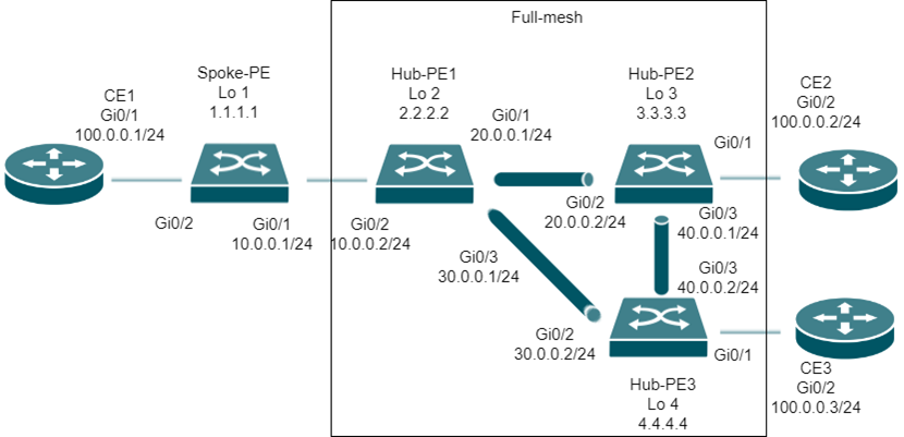
H‑VPLS (Hierarchical Virtual Private LAN Service) is an enhanced and scalable form of VPLS designed for large‑scale networks. When the number of devices in a VPLS domain grows, a full‑mesh VPLS topology becomes complex and costly. H‑VPLS addresses this issue by introducing a hierarchical structure that separates access nodes (UPEs) from service/core nodes (SPEs). This layered design simplifies the network topology, reduces the number of VPLS peer connections, and lowers overall deployment and operational costs, while still providing transparent Layer‑2 connectivity for users.
The configuration of LDP‑based H‑VPLS follows a clear step‑by‑step approach. First, IP connectivity between all nodes must be ensured using static routes or an IGP such as IS‑IS. MPLS and MPLS LDP are then enabled globally and on all relevant interfaces, with Loopback addresses configured as LSR IDs. MPLS L2VPN is enabled on PE devices.
On SPE devices, a VSI is created and full‑mesh VPLS peers are established between SPEs, while peers facing UPEs are configured as spoke peers. On UPE devices, a VSI is also created, but only normal mesh peers toward SPEs are configured. Finally, CE interfaces are configured to complete user access, enabling efficient and scalable L2VPN services across large networks.
The following is a reference application example and CLI configuration commands.
Step 1. Spoke‑PE Configuration
CLI:
router isis 100
net 00.0001.0000.0000.1111.00
#
mpls
mpls ldp
lsr-id 1.1.1.1
transport-address 1.1.1.1
targeted-peer 2.2.2.2
exit-targeted-peer
#
mpls l2vpn
#
vsi Temple-vsi vsi-id 200
signaling ldp
peer 2.2.2.2
#
#
interface vlan 1
ip address-alloc dhcp
#
interface loopback 1
ip address 1.1.1.1 255.255.255.255
ip router isis 100
#
interface gigabitEthernet 1/0/1
no switchport
ip address 10.0.0.1 255.255.255.0
ip router isis 100
mpls
mpls ldp
#
interface gigabitEthernet 1/0/2
no switchport
no ip address
l2vpn-binding vsi Temple-vsi
Step 2. Hub‑PE 1 Configuration
CLI:
router isis 100
net 00.0001.0000.0000.1112.00
#
mpls
mpls ldp
lsr-id 2.2.2.2
transport-address 2.2.2.2
targeted-peer 1.1.1.1
exit-targeted-peer
targeted-peer 3.3.3.3
exit-targeted-peer
targeted-peer 4.4.4.4
exit-targeted-peer
#
mpls l2vpn
#
vsi Temple-vsi vsi-id 200
signaling ldp
peer 1.1.1.1 spoke
peer 3.3.3.3
peer 4.4.4.4
#
#
interface vlan 1
ip address-alloc dhcp
#
interface loopback 2
ip address 2.2.2.2 255.255.255.255
ip router isis 100
#
interface gigabitEthernet 1/0/1
no switchport
ip address 20.0.0.1 255.255.255.0
ip router isis 100
mpls
mpls ldp
#
interface gigabitEthernet 1/0/2
no switchport
ip address 10.0.0.2 255.255.255.0
ip router isis 100
mpls
mpls ldp
#
interface gigabitEthernet 1/0/3
no switchport
ip address 30.0.0.1 255.255.255.0
ip router isis 100
mpls
mpls ldp
Step 3. Hub‑PE 2 Configuration
CLI:
router isis 100
net 00.0001.0000.0000.1113.00
#
mpls
mpls ldp
lsr-id 3.3.3.3
transport-address 3.3.3.3
targeted-peer 2.2.2.2
exit-targeted-peer
targeted-peer 4.4.4.4
exit-targeted-peer
#
mpls l2vpn
#
vsi Temple-vsi vsi-id 200
signaling ldp
peer 2.2.2.2
peer 4.4.4.4
#
#
interface vlan 1
ip address-alloc dhcp
#
interface loopback 3
ip address 3.3.3.3 255.255.255.255
ip router isis 100
#
interface gigabitEthernet 1/0/1
no switchport
no ip address
l2vpn-binding vsi Temple-vsi
#
interface gigabitEthernet 1/0/2
no switchport
ip address 20.0.0.2 255.255.255.0
ip router isis 100
mpls
mpls ldp
#
interface gigabitEthernet 1/0/3
no switchport
ip address 40.0.0.1 255.255.255.0
ip router isis 100
mpls
mpls ldp
Step 4. Hub‑PE 3 Configuration
CLI:
router isis 100
net 00.0001.0000.0000.1114.00
#
mpls
mpls ldp
lsr-id 4.4.4.4
transport-address 4.4.4.4
targeted-peer 2.2.2.2
exit-targeted-peer
targeted-peer 3.3.3.3
exit-targeted-peer
#
mpls l2vpn
#
vsi Temple-vsi vsi-id 200
signaling ldp
peer 2.2.2.2
peer 3.3.3.3
#
#
interface vlan 1
ip address-alloc dhcp
#
interface loopback 4
ip address 4.4.4.4 255.255.255.255
ip router isis 100
#
interface gigabitEthernet 1/0/1
no switchport
no ip address
l2vpn-binding vsi Temple-vsi
#
interface gigabitEthernet 1/0/2
no switchport
ip address 30.0.0.2 255.255.255.0
ip router isis 100
mpls
mpls ldp
#
interface gigabitEthernet 1/0/3
no switchport
ip address 40.0.0.2 255.255.255.0
ip router isis 100
mpls
mpls ldp
Conclusion
This FAQ introduces the VPWS/VPLS feature and explains how to configure it using the switch CLI.
Get to know more details of each function and configuration please go to Download Center to download the manual of your product.
