


Contents
Introduction
This article will introduce how to configure separate management VLANs for Omada managed switches and APs and a client VLAN other than VLAN 1 and isolate them with the clients connected.
When configuring the network, many customers would like to change the management VLANs for the controller, gateway, AP and switch, then set another VLAN for clients, in this way, different kinds of devices are managed in different VLANs, and the clients connected won’t be able to access the devices, enhancing the network security.
This guide suits the configuration for a completely new network for SOHO scenario usage which means you don’t have any configurations like management VLANs before, and also the network scale is simple and typical. If you want to configure a set of professional business network or already have a set of network configuration and want to integrate the Omada devices into the network, please refer to the How to configure Management VLANs for Omada Switches and APs (for Business scenario).
Usually, the topologies are like the following, connecting the controller directly on gateway:

As shown in the topology, the final goal is to shutdown VLAN 1 from the network, set VLAN20 for clients usage, all the clients connected will obtain IP address at 192.168.20.x/24, set VLAN 30 for switch management, and the switches will use a management IP at 192.168.30.x/24, VLAN 40 for AP management, and the APs will use a management IP at 192.168.40.x/24, for gateway and controller, their VLAN will still remain default, but change to another VLAN ID, you can also change the IP addresses for them.
The detailed configuration steps based on the example shown in the topologies above will be introduced in later paragraphs.
Requirements
- Omada Controller (Software Controller / Hardware Controller / Cloud Based Controller, V6.0 and above)
- Omada Smart, L2+ and L3 switches
- Omada APs
- Omada Gateway
Configuration
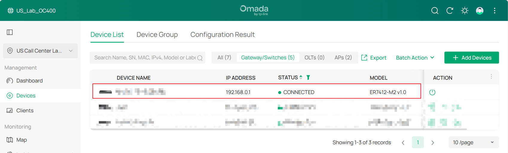
Step 1. Adopt the gateway in default VLAN.
Step 2. Create the Networks needed.
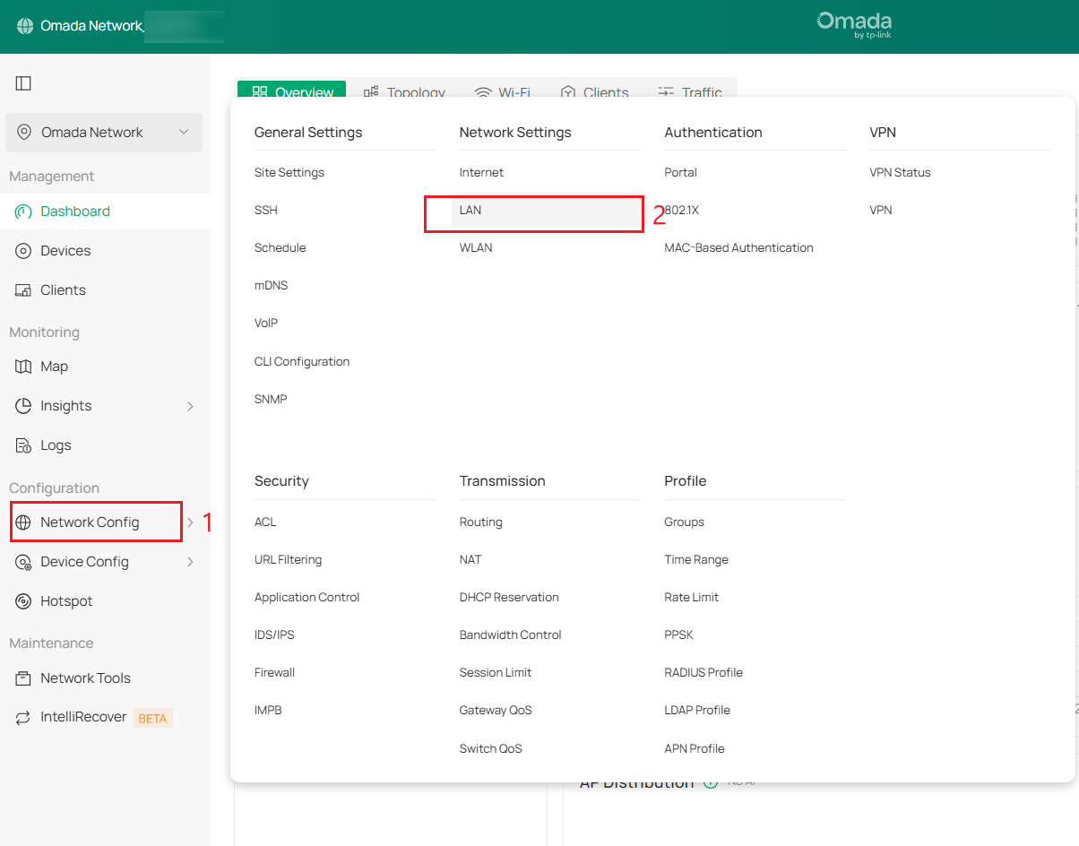
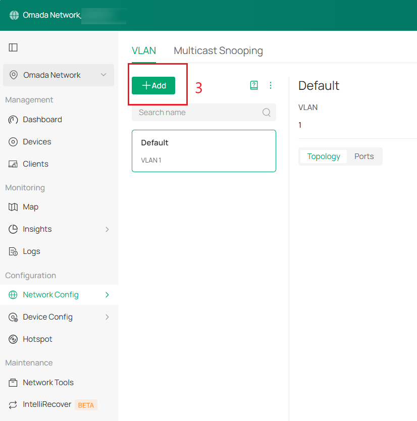
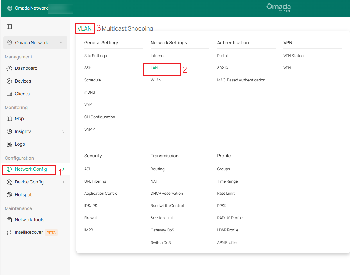
First, create the Client Network (VLAN 20), SW MGMT Network (VLAN 30), and AP MGMT Network (VLAN 40). Go to Network Config > Network Settings > LAN > VLAN, click +Add to create a new LAN network.
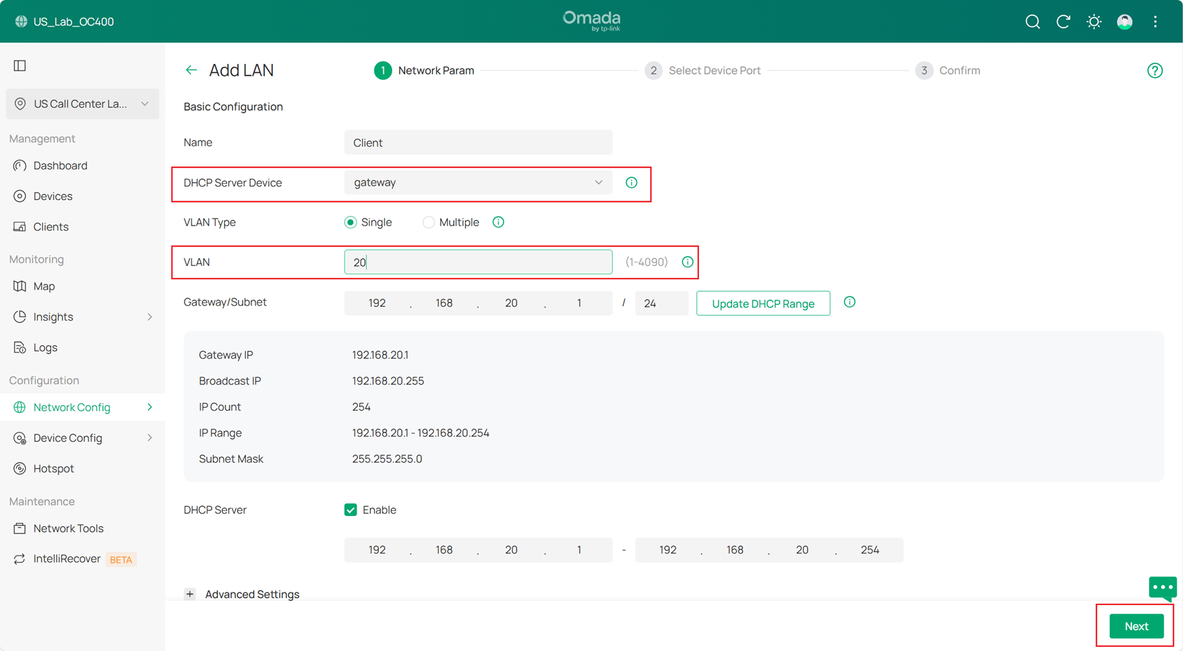
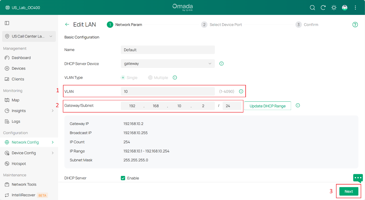
Below is the example of Client Network (VLAN 20), set the DHCP Server Device to gateway and VLAN, and then configure Gateway Address/Subnet. And click Next to Select Device Port, click Skip and Apply to apply the configuration.
Then create SW MGMT Network, AP MGMT Network and Core MGMT Network as the same method.
Step 3. Configure the default VLAN.
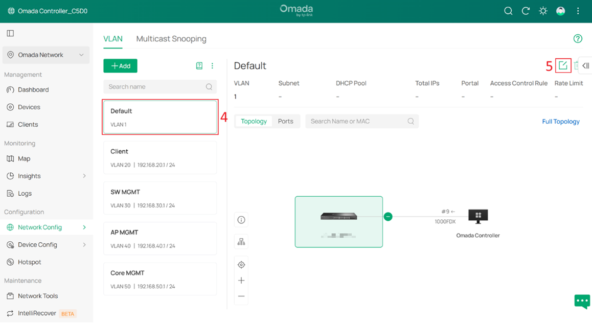
Go to Network Config > Network Settings > LAN > VLAN, select Default, and click Edit.
Change the VLAN ID and subnet IP address so that the Default Network no longer uses VLAN 1. In this example, change it to VLAN 10. For the Gateway/Subnet, set it to 192.168.10.x/24. In this example, it is set to 192.168.10.2, which is the gateway IP address.
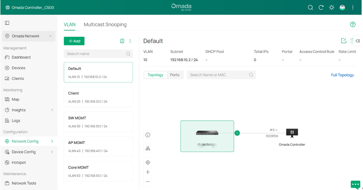
The result should appear as shown below:
Step 4. Connect and adopt all switches and APs.
After the switches and APs are connected, they should obtain IP addresses from the Default Network (subnet 192.168.10.0/24).
Step 5. Configure the Management VLAN for switches.
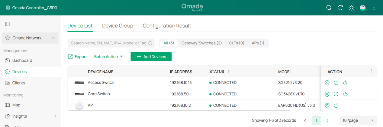
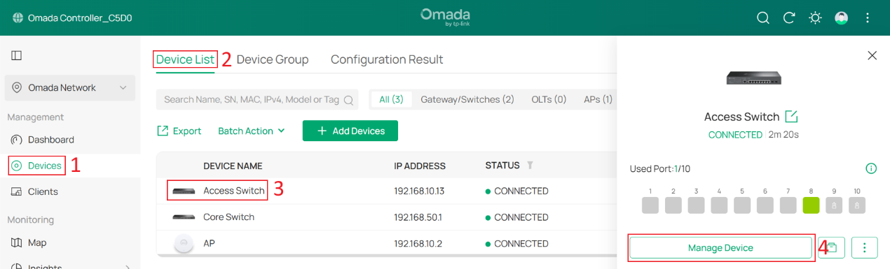
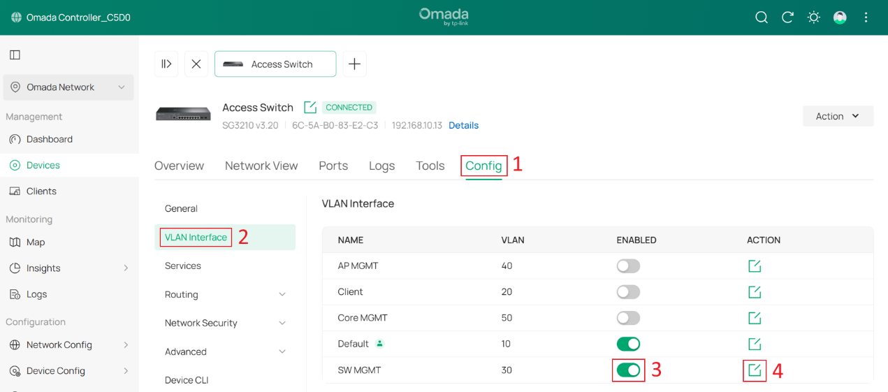
Go to Devices > Device List, click a switch and Manage Device to enter its private configuration page, then go to Config > VLAN Interface, Enable SW MGMT and click Edit.
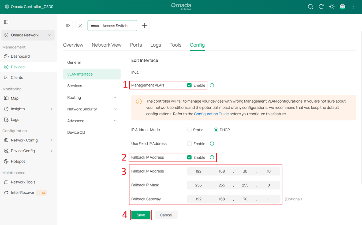
Tick the Enable box to set this VLAN interface as the Management VLAN. Optionally, configure the Fallback IP, Fallback IP Mask and Fallback Gateway. These settings are used when the device fails to obtain an IP address via DHCP, ensuring continued management access.
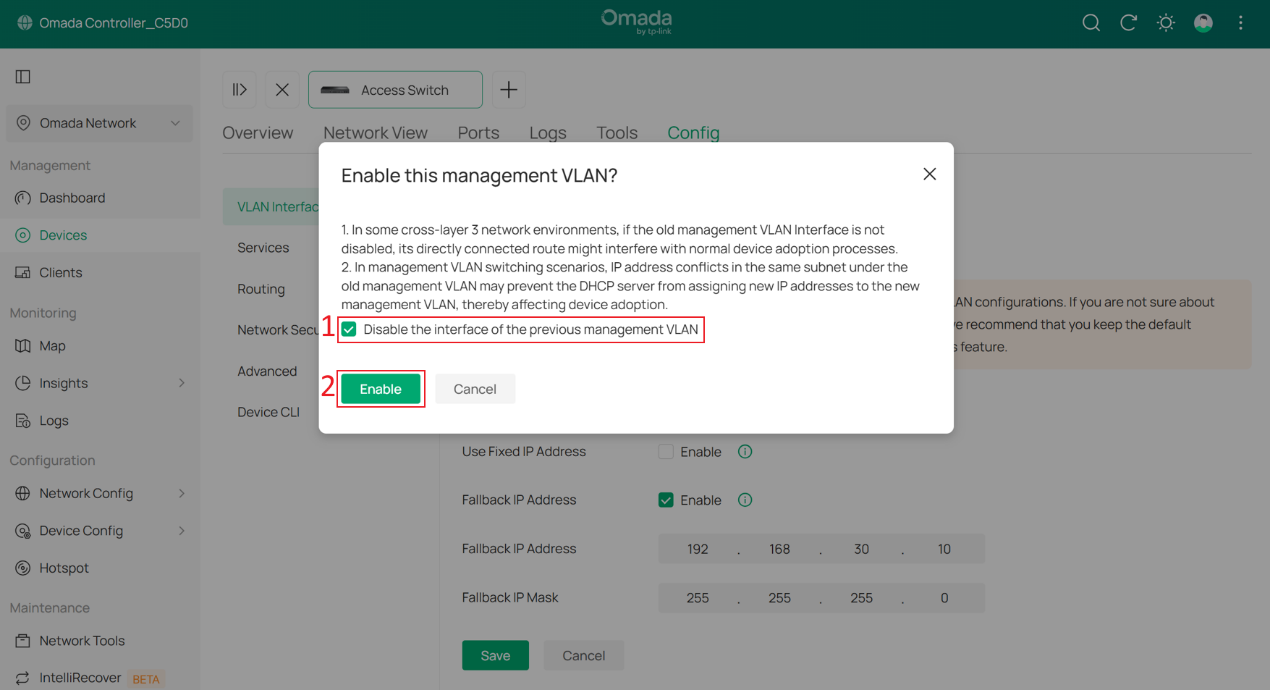
In this example, they are set to 192.168.30.10, 255.255.255.0 and 192.168.30.1. Click Save.
In the pop-up window, check Disable the interface of the previous management VLAN.
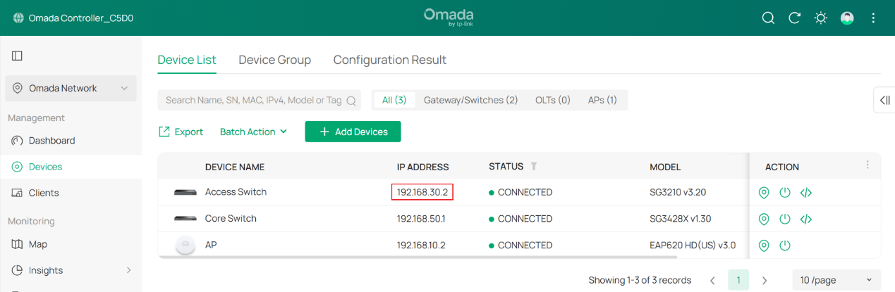
Wait a moment for the configuration to take effect. The switch may be reprovisioned during this process. Once the Management VLAN switch is complete, you will find that the switch’s IP address has changed to the subnet of SW MGMT.
Step 6. Configure the Management VLAN for APs.
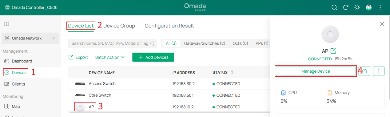
Go to Devices > Device List, click an AP and Manage Device to enter its private configuration page, then go to Config > General.
Change Management VLAN to Custom, and set LAN Network to AP MGMT.
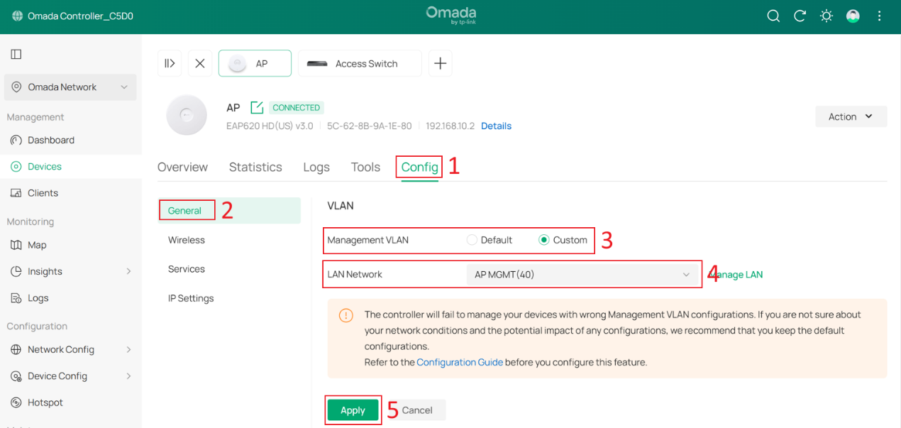
Wait a moment for the configuration to take effect. Once completed, you will find that the AP’s IP address has changed.
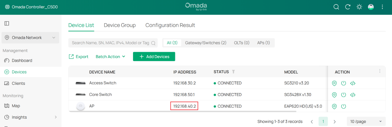
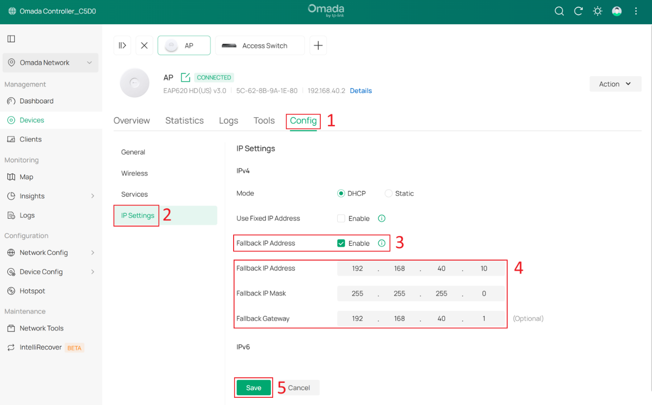
Optionally, you can configure the Fallback IP, Fallback IP Mask and Fallback Gateway by go to Config > IP Settings. In this example, they are set to 192.168.40.10, 255.255.255.0, and 192.168.40.1.
Step 7. Configure switch port VLAN configuration for the Client Network.
To ensure that all wired clients can obtain IP addresses from the Client Network, we need to change the port VLAN configuration of all downlink ports on the switches that are directly connected to end devices.
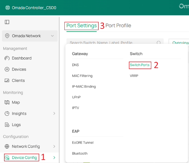
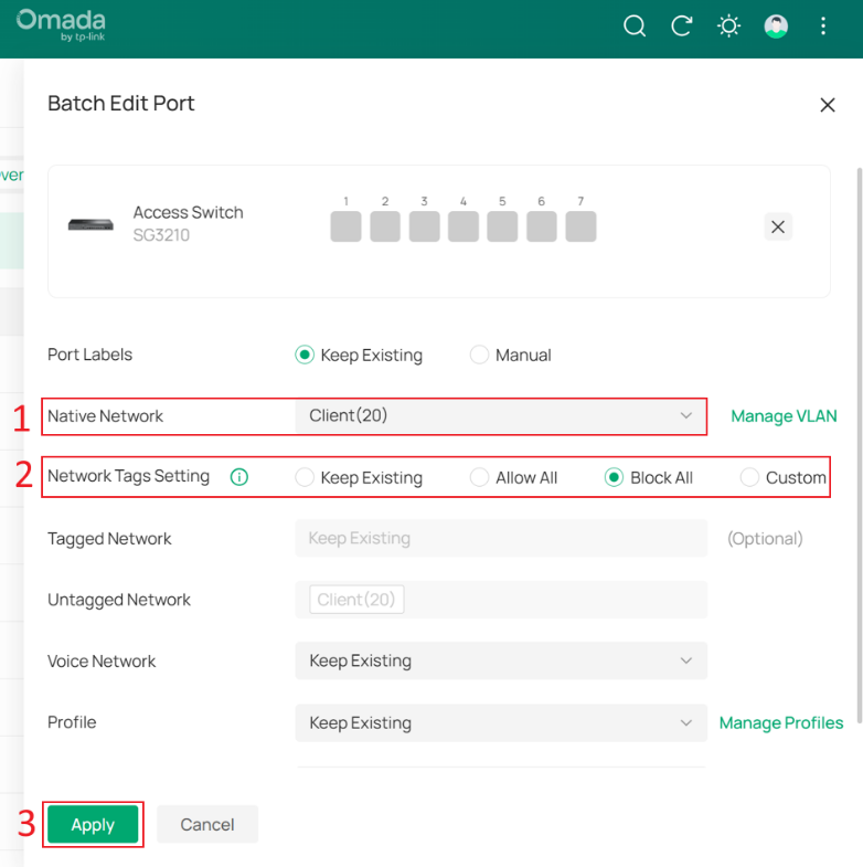
Go to Device Config > Switch > Switch Ports, select the downlink ports that are directly connected to client devices, and then click Edit Selected to batch modify their port profiles.
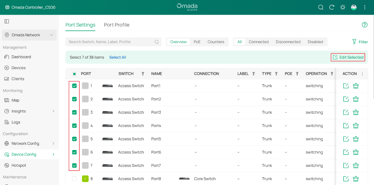
Change the Native Network of these ports to Client, set Network Tags Setting to Block All, and then click Apply to save the configuration.
Step 8. Configure the SSID for wireless clients.
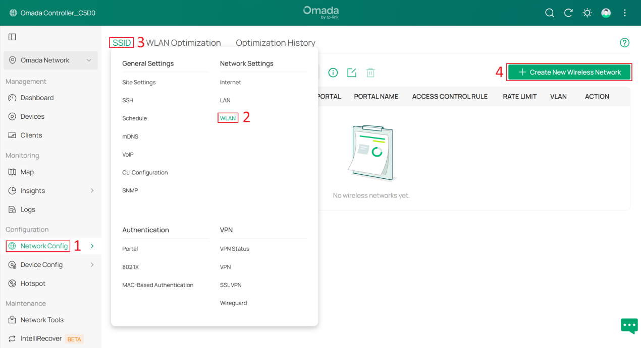
Go to Network Config > Network Settings > WLAN > SSID, and click +Create New Wireless Network.
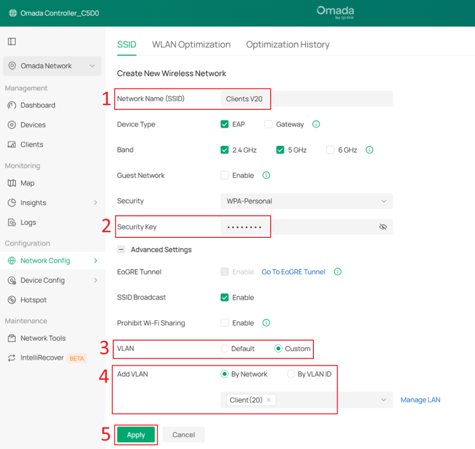
Set the SSID name and password, then expand Advanced Settings. Set VLAN to Custom, select By Network under Add VLAN, and choose the Client network that was created earlier.
Click Apply to save the configuration.
Note that after SSID VLAN is configured, all packets sent by clients under that SSID will carry the corresponding VLAN tag. Similarly, only packets with the VLAN tag corresponding to that SSID VLAN can be forwarded to clients under that SSID.
If both SSID VLAN and Dynamic VLAN are configured on the same SSID, Dynamic VLAN takes higher priority.
Step 9. Create IP Groups and ACL Rules to prevent clients from accessing the Controller and other Omada Devices.
Currently, some networks use the Core Switch as the DHCP server, so they cannot be selected as a Network in Switch ACL rules. Therefore, we must first create IP Groups and then create ACL rules based on these IP Groups.
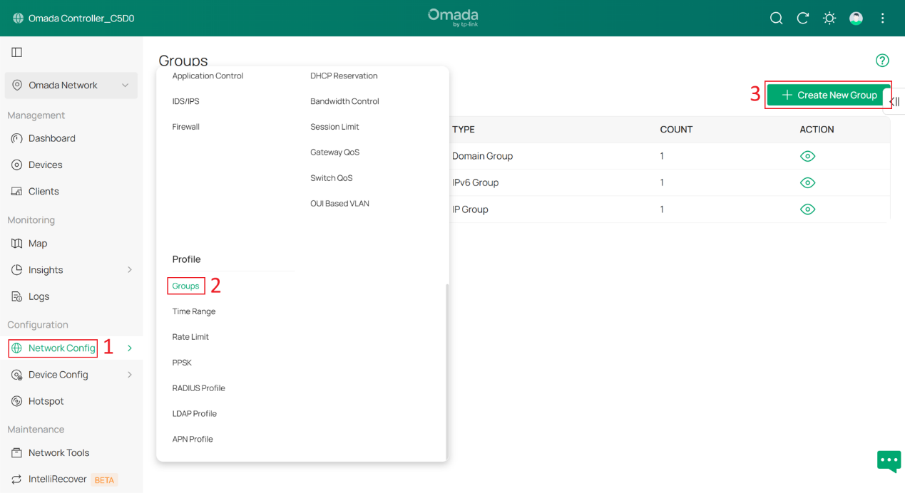
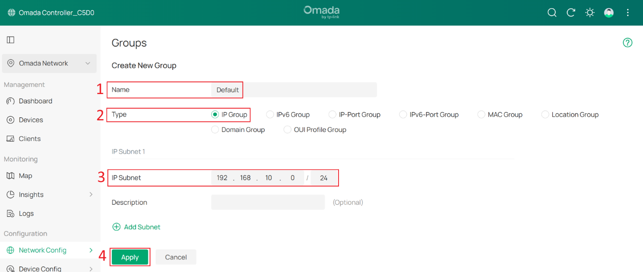
Go to Network Config > Profile > Groups, and click +Create New Group.
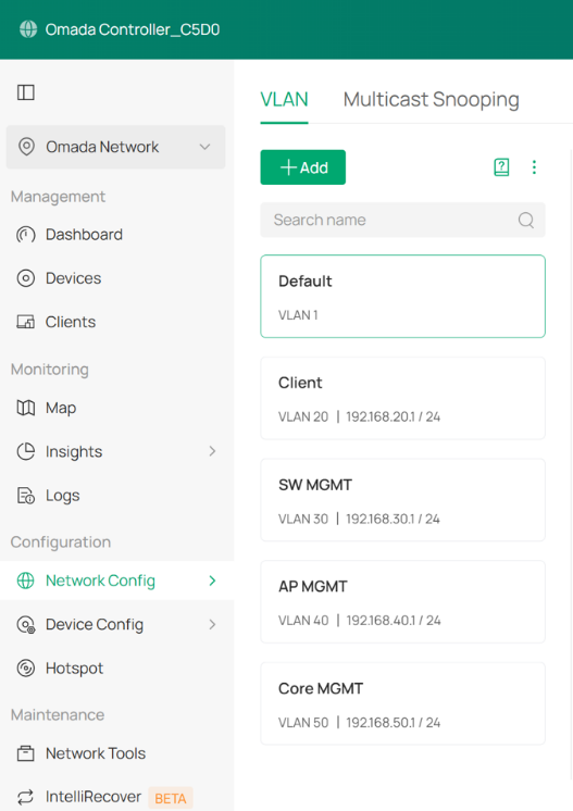
Create one IP Group for each subnet. In this example, there are five subnets: Default, Client, SW MGMT, AP MGMT, and Core MGMT.
Enter a group name, set the Type to IP Group, and enter the network address of each subnet in IP Subnet. For example, the IP subnet of the Default group is 192.168.10.0/24. Click Apply to save the configuration.
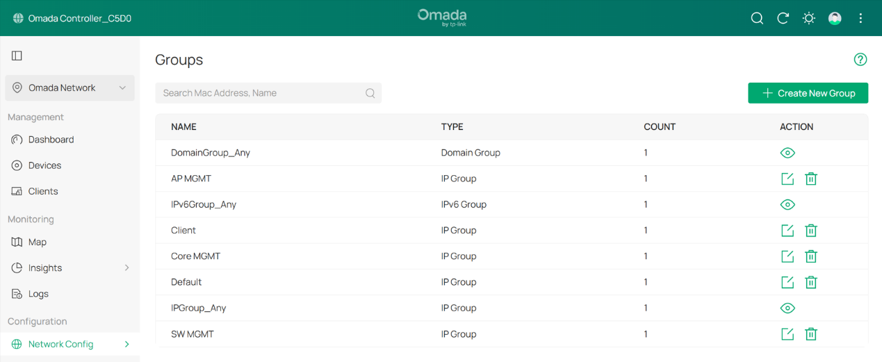
The result should appear as shown below:
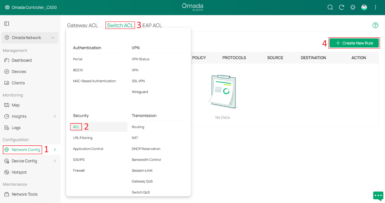
Next, go to Network Config > Security > ACL > Switch ACL, and click +Create New Rule to create a new ACL rule.
Enter a rule name as the Description, select Deny for Policy, and choose All for Protocol. For both Source and Destination, set the type to IP Group. Select the Client group as the Source, and select all other management groups as the Destination. Click Create to apply the rule.
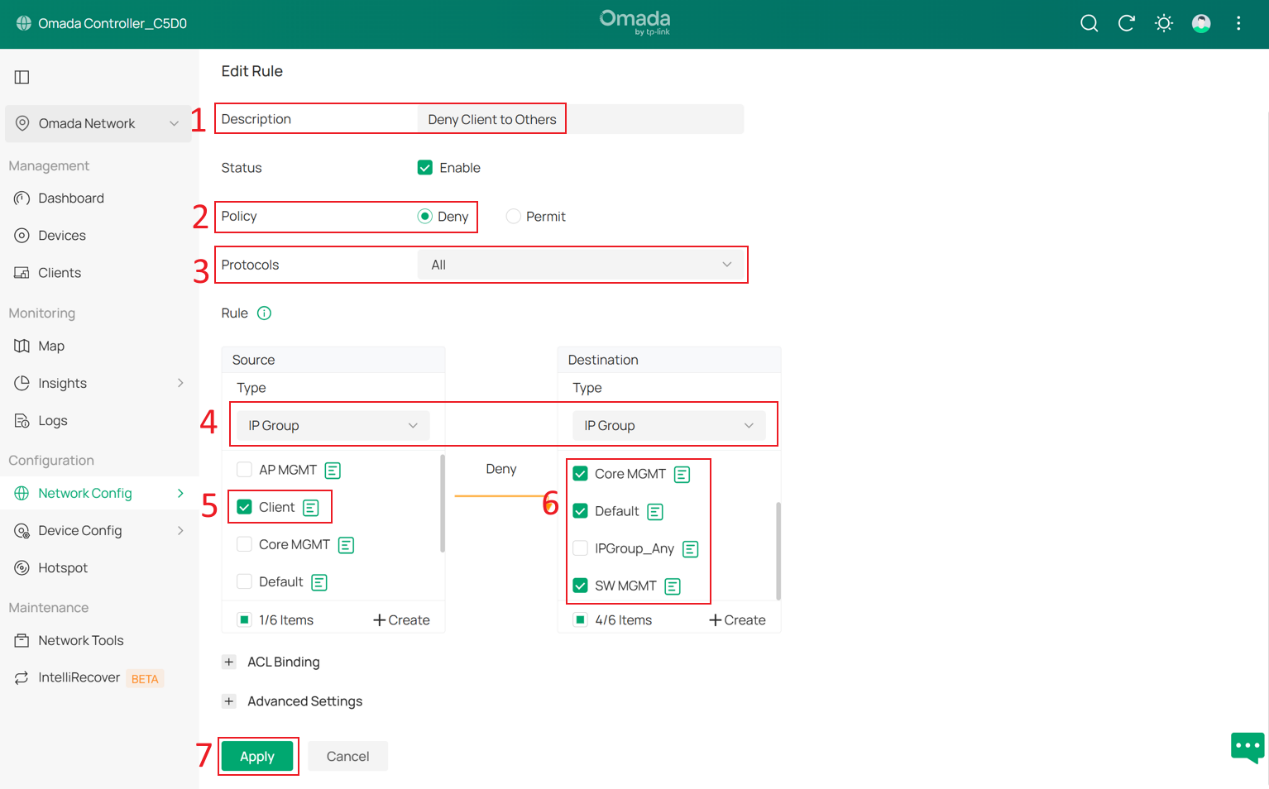
With this ACL rule in place, when client devices connect and obtain IP addresses from the 192.168.20.0/24 subnet, they will be unable to access the Omada Controller or other Omada devices, thereby enhancing overall network security.
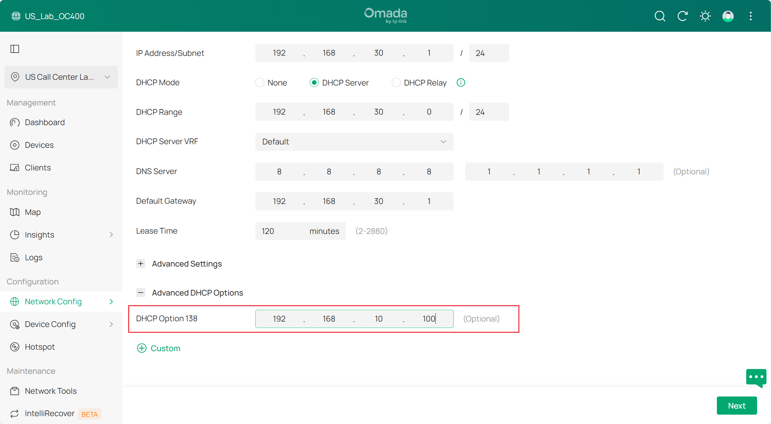
Step 10. Set DHCP Option 138 on all DHCP Servers.
DHCP Option 138 is used to inform devices of the Controller’s IP address during the DHCP process. This configuration is required because eventually all network devices will not be in the same VLAN; they need DHCP Option 138 to discover the Controller and be adopted.
In this example, DHCP Option 138 is set to 192.168.10.100, and the Controller will be assigned this IP address in later steps.
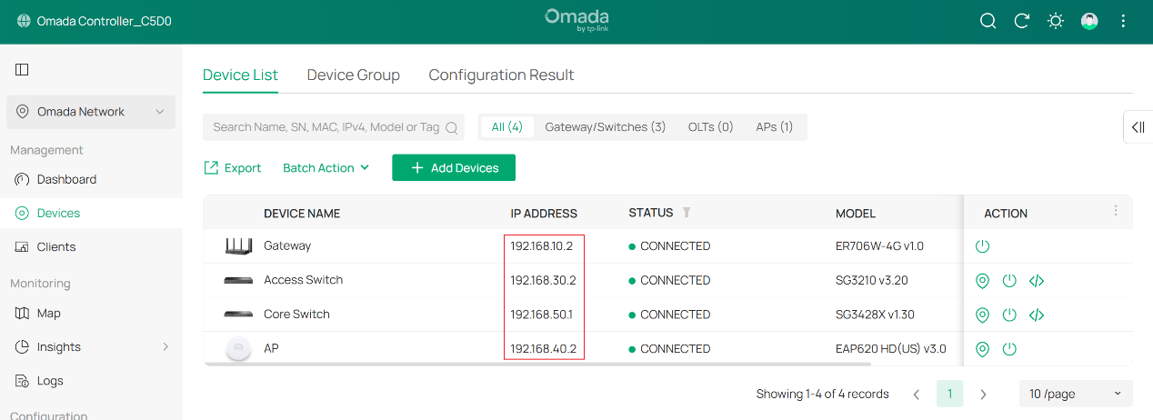
Final result should be like this:
Verification
After this configuration, the gateway, switches and APs are in different management Networks.
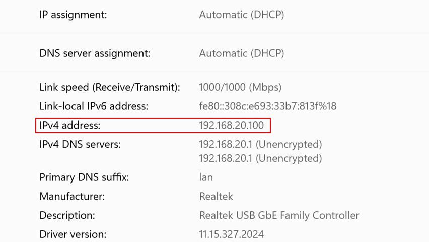
The wired PC connected on the switch is obtaining IP address from the clients VLAN 192.168.20.0/24 :
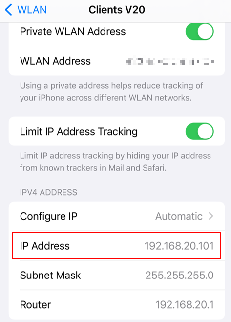
The phone connected wirelessly is obtaining IP address from clients VLAN 192.168.20.0/24:
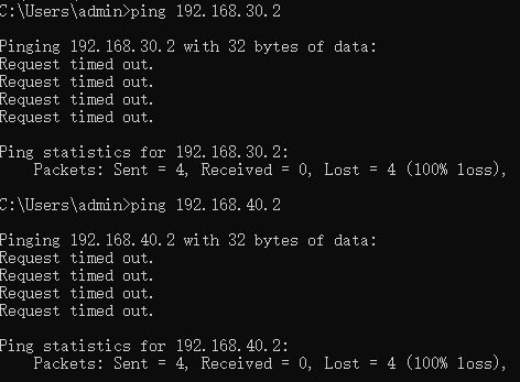
The client cannot access managed network devices:
Conclusion
Till now we have introduced how to set up a new network and use different VLAN networks to manage gateways, switches, APs, then connect clients in a specific VLAN and isolate them with the network devices.
Get to know more details of each function and configuration please go to Download Center to download the manual of your product.

