


Scenario 1: Via Port Forwarding & Omada discovery utility/Inform URL/DHCP option 138
Scenario 2: Via VPN Tunnel & DHCP option 138
Introduction
In enterprise networks, devices are often deployed across different subnets, making it common for Omada devices and the Omada Controller to reside in separate network segments. Supporting device adoption and management across subnets enables centralized control without changing existing network designs. This capability simplifies deployment, reduces maintenance costs, and improves scalability and operational efficiency, which is essential for distributed, campus, and multi-branch network environments.
This article introduces different methods for adopting devices across subnets over the Internet and using Omada Controller v6 and higher.
Requirements
- Omada Discovery Utility
- Omada Software/Hardware/Cloud-Based Controller
- Omada Devices(Gateway/EAP/Switch)
Check compatible devices here: Omada Controller Compatibility List
Configuration
Scenario 1: Via Port Forwarding & Omada discovery utility/Inform URL/DHCP option 138
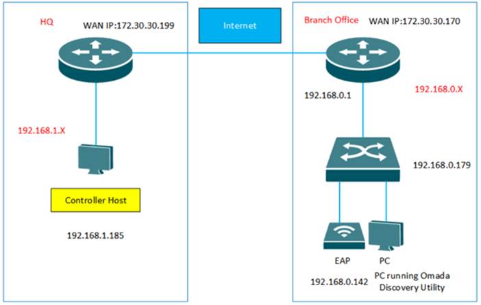
A classic office scenario is shown below. The headquarters and the branch office are connected via the Internet. In HQ, there is an Omada Controller and a gateway in subnet 192.168.1.0/24. In the Branch Office, there is an EAP, a switch and a gateway in subnet 192.168.0.0/24.
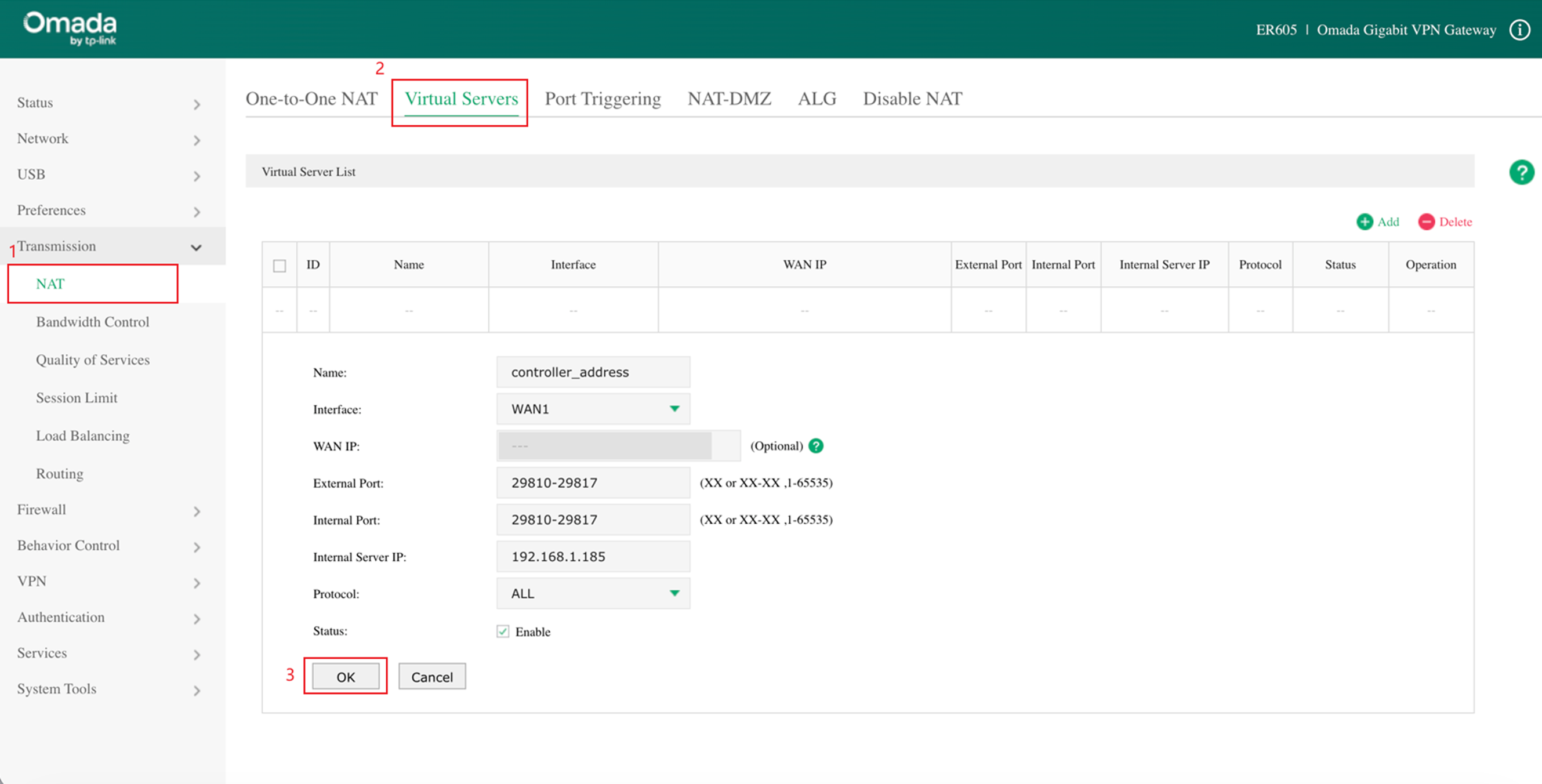
Step 1. Configure Port Forwarding rules on gateway (taking ER605 as an example) in HQ for Controller Host (192.168.1.185). Please go to Transmission>NAT>Virtual Server and configure a virtual server for TCP&UDP port, ranging from 29810 to 29817.
Note: If your devices are not crossing the Internet and are all under the same gateway, with only different VLANs, you can skip this step.
Step 2. Three methods for Omada Controller to discover the Omada devices in the Branch Office.
-
Method 1: Omada Discovery Utility
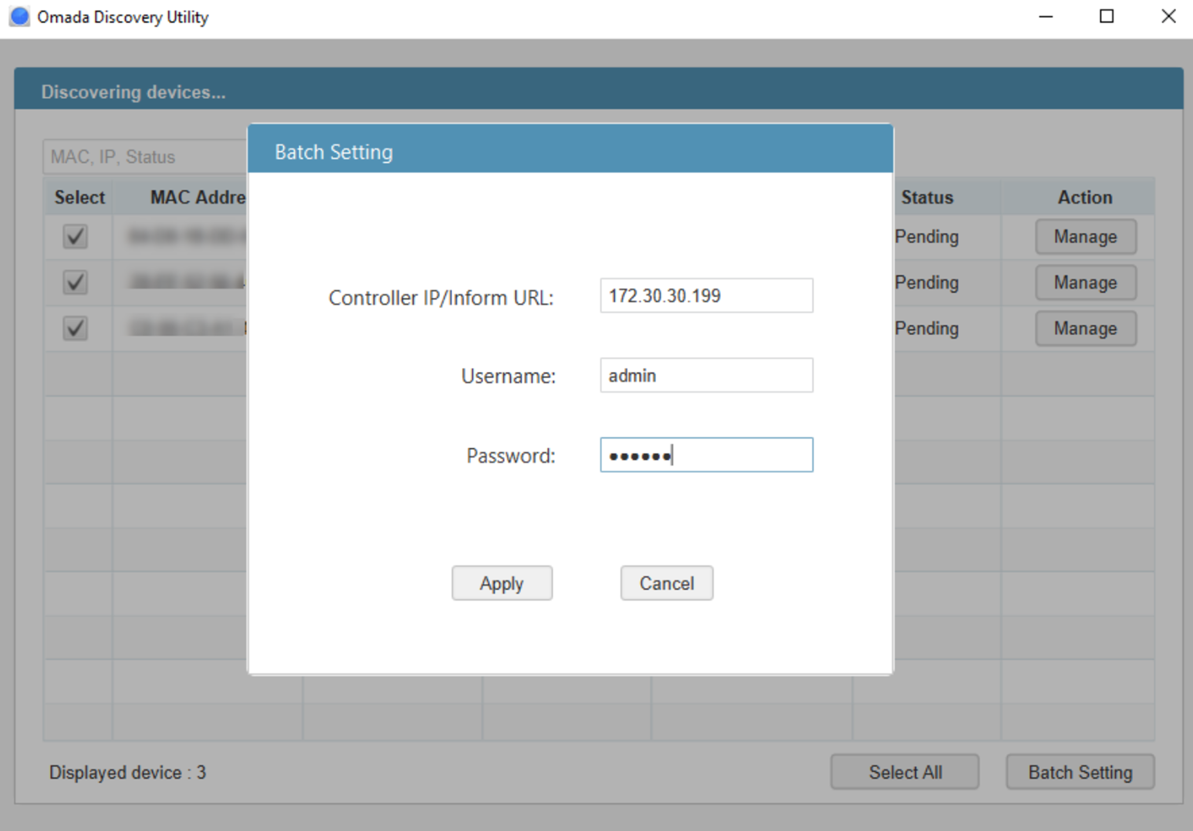
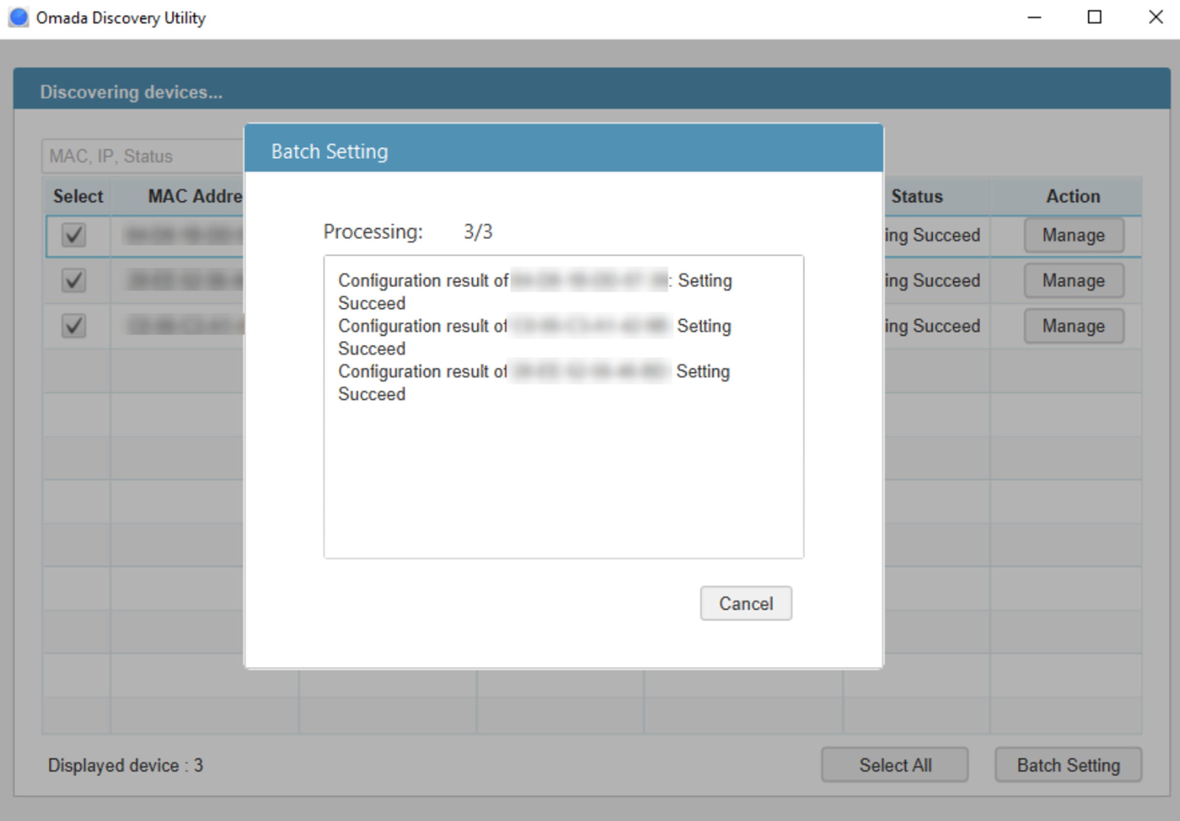
Run Omada Discovery Utility in Branch Office, select the Omada devices, and click “Batch Setting”. Fill in the Controller Hostname/IP with WAN IP address of ER605 in HQ which is 172.30.30.199 and the Username/Password of the Omada devices. At last, click “Apply”. The default username/Password of the devices is admin/admin. If the Username and Password of Omada devices are not the same, please manage the devices one by one.
-
Method 2: Controller Inform URL
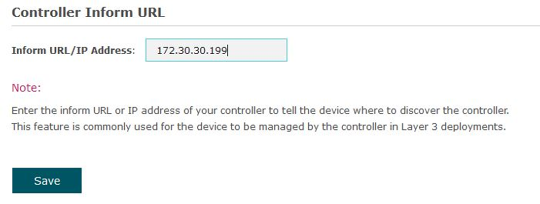
In Standalone mode, please go to System Tools/System-Controller settings of every Omada device, fill in the Controller IP/Inform URL with the WAN IP address of ER605 in HQ which is 172.30.30.199. Then click Save.
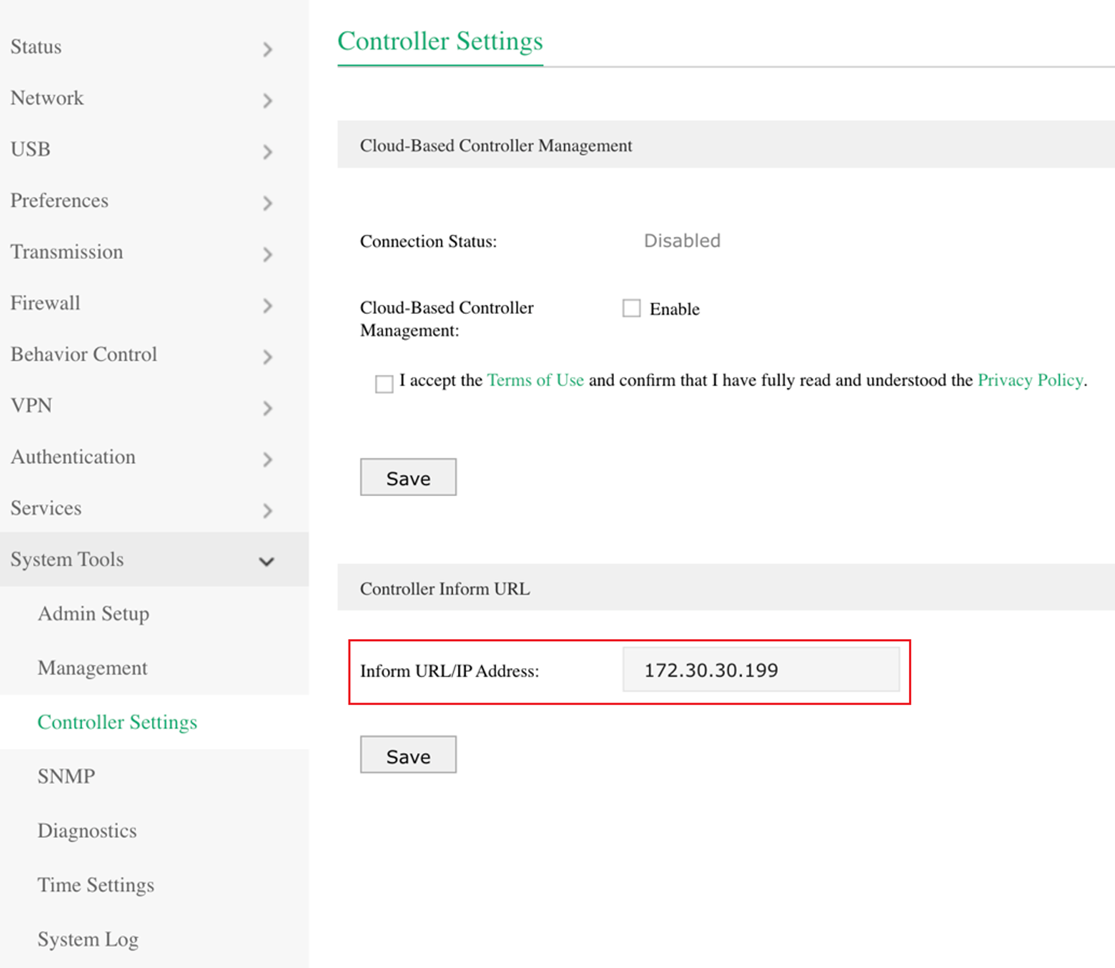
Configuration screenshot of switch Controller Settings in standalone mode.
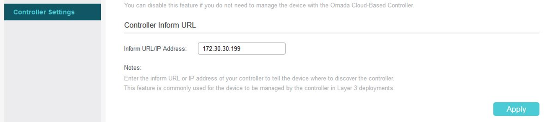
Configuration screenshot of EAP660 Controller Settings in standalone mode.
-
Method 3: DHCP Option 138
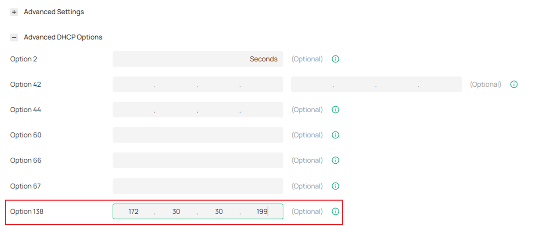
Use Omada Discovery Utility or set Controller Inform URL to adopt the ER605 in Branch Office on another site. And then go to Network Config > LAN, click Edit/Add button of the LAN where the DHCP clients are located. Enable DHCP Server and configure common DHCP parameters. Then click Advanced DHCP Options and specify Option 138 as the Controller’s IP address, which is the WAN IP of ER605 in HQ. Click Save.
To make DHCP Option 138 take effect, you need to renew DHCP parameters for the DHCP clients. One possible way is to disconnect the switch and EAP and then reconnect them.
Note: If you do not use Omada Gateway, you also can use DHCP Server which supports the option 138 feature to finish the configuration.
Step 3. After finishing the configuration of the Omada devices in the Branch Office will appear on the “PENDING” list of Omada Controller, which means you can adopt and manage these devices now.
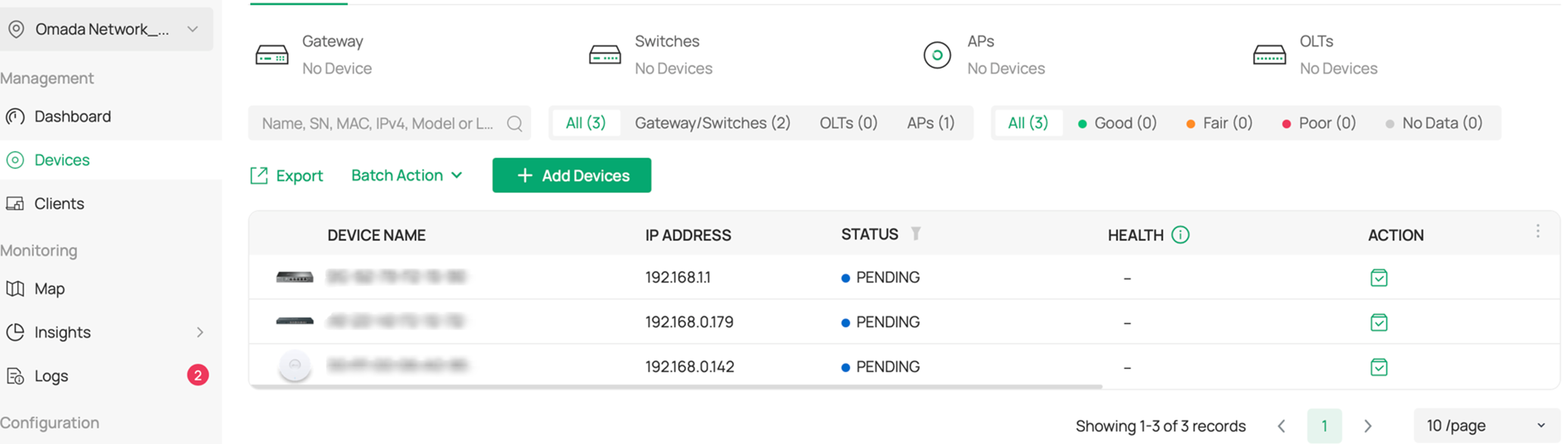
Note: If you have adopted a gateway in the default site, please click “Add New Site” in the drop-down list of Sites and configure the parameters of the Branch Office. Because one site can only adopt one gateway.
Scenario 2: Via VPN Tunnel & DHCP option 138
As shown below, the HQ and Branch Office are connected with each other through the IPSec VPN tunnel. In HQ, there is an Omada Controller and an ER605(VPN router) in subnet 192.168.1.0/24. In the Branch Office, there is an EAP2, a switch as the DHCP Server (supporting DHCP option 138), and an ER605 (VPN router) in subnet 192.168.10.0/24.
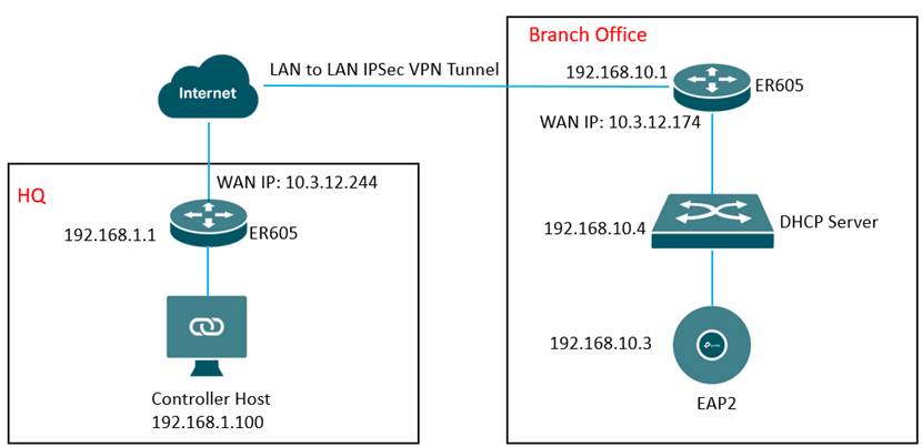
Step 1. Configurations on the switch in the Branch Office.
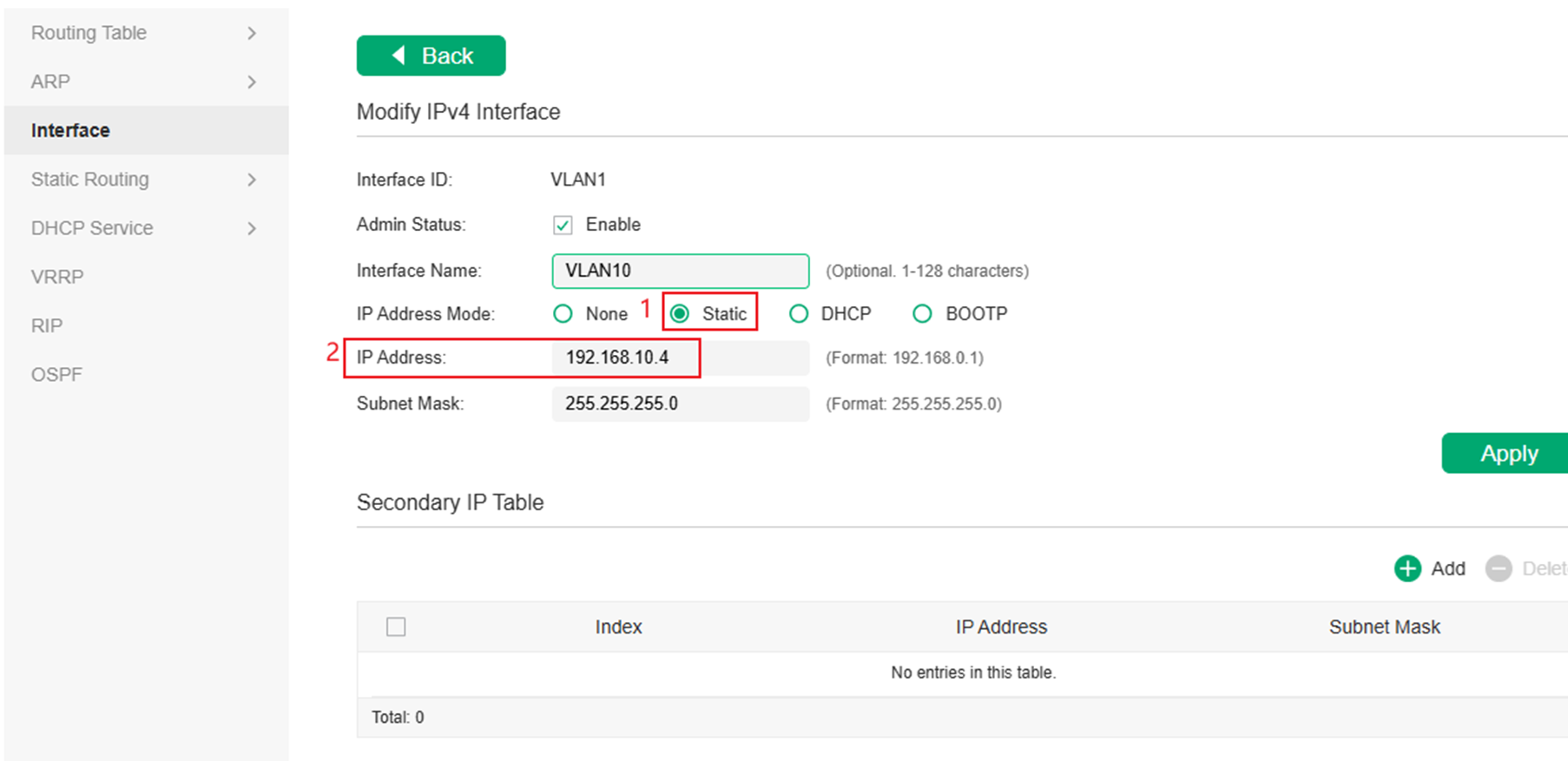
Change the switch’s default IP address to 192.168.10.4 to avoid IP conflict with the gateway.
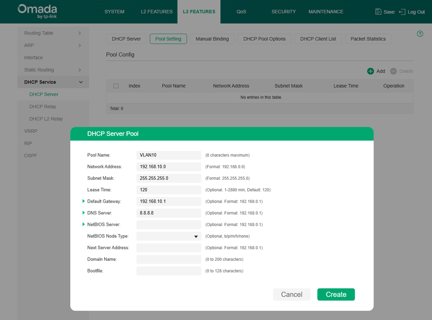
Enable DHCP Server Function on switch and set DHCP Option138 as the IP address of Remote Omada Controller Host (192.168.1.100). And then the DHCP Server will tell the EAPs where the Omada Controller is, so that the Omada Controller and EAPs can communicate with each other among different subnets.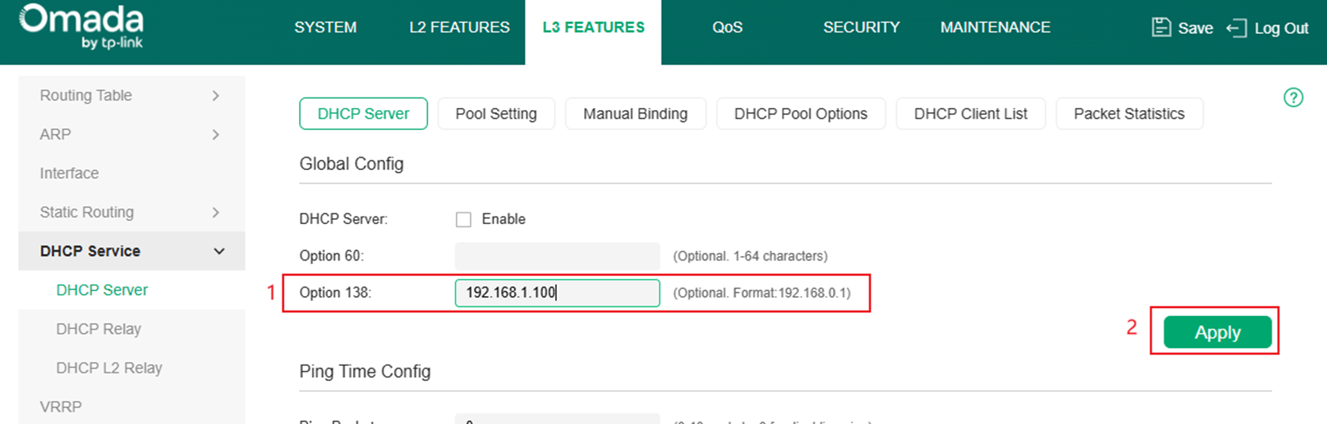
Configure the DHCP IP Address Pool (192.168.10.0/24) for EAP in the Branch Office.
Step 2. Set up Site-to-Site Manual IPsec VPN Tunnels.
- Create a new VPN policy on the Gateway managed by Omada Controller in headquarter
Note: IPSec VPN is used as an example for demonstration. Establishing other types of VPN tunnels can also be used to achieve device adoption.
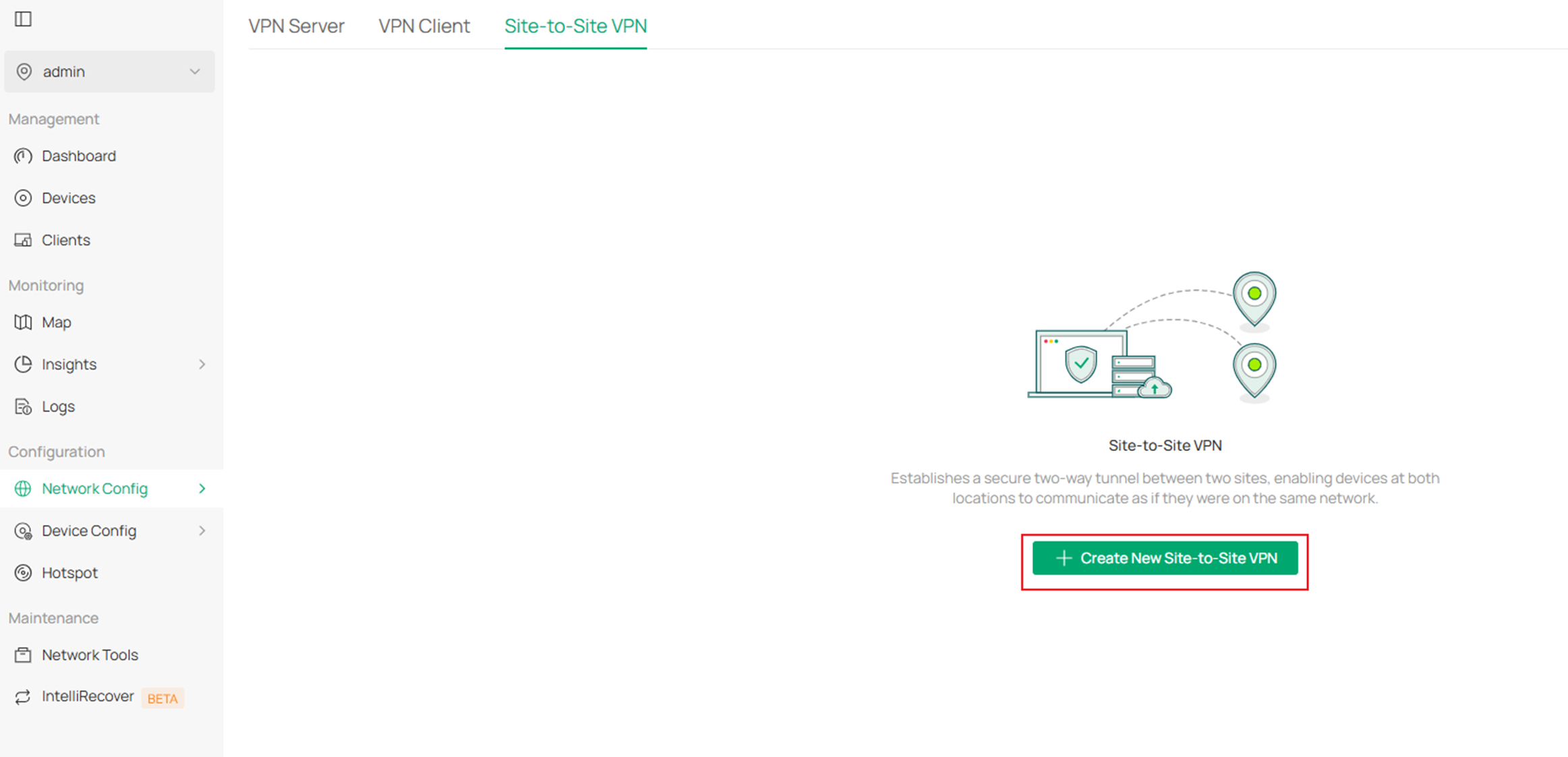
Create a new VPN policy on the Gateway managed by Omada Controller in HQ. Go to Network Config > VPN> Site-to-Site VPN and click Create New Site-to-Site VPN.
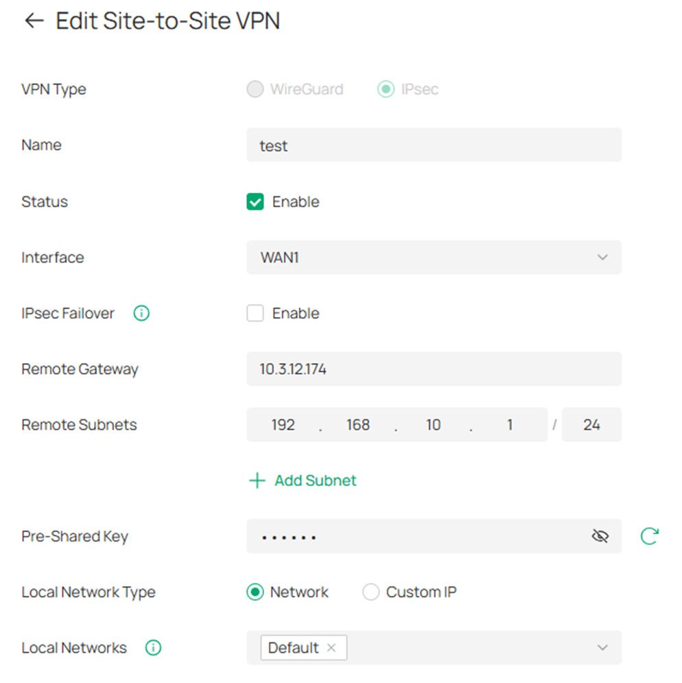
Configure the parameters for the new VPN policy. Enter a name to identify the VPN policy, select the VPN Type for the new entry as IPsec and the Mode as Manual. Then configure the corresponding parameters and save them.
|
Interface |
Select the WAN port on which the VPN tunnel will be established. |
|
Remote Gateway |
Enter the WAN IP address of Gateway in the Branch Office (10.3.12.174). |
|
Remote Subnets |
Enter the IP address range of the LAN in the Branch Office (192.168.10.1/24). |
|
Local Networks |
Select the networks in the headquarters (LAN 1), and the VPN policy will be applied to the selected networks. |
|
Pre-Shared Key |
Enter the Pre-Shared Key (PSK) that serves as an authentication key. The gateway in the headquarters and the Branch Office must use the same PSK for authentication. |
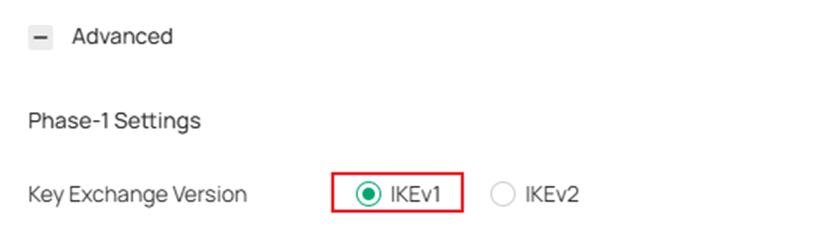
Note: When gateway in Branch Office is in standalone mode, click Advanced Settings and select IKEv1 as Key Exchange Version. IKEv1 only supports a single local network.
If the Omada Gateway is behind a NAT device, make sure that UDP port 500 and UDP port 4500 are open on the NAT device, and set up the Local ID Type / Remote ID Type as Name.
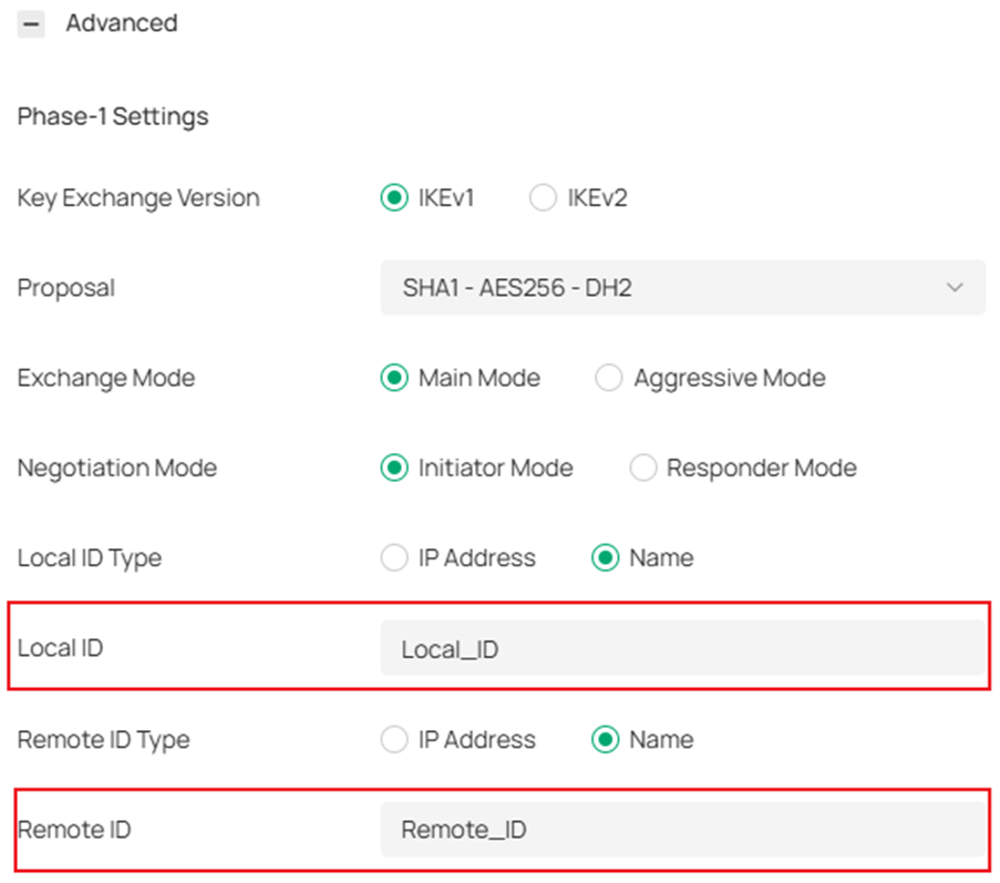
- Create a new VPN policy on the gateway in the branch office
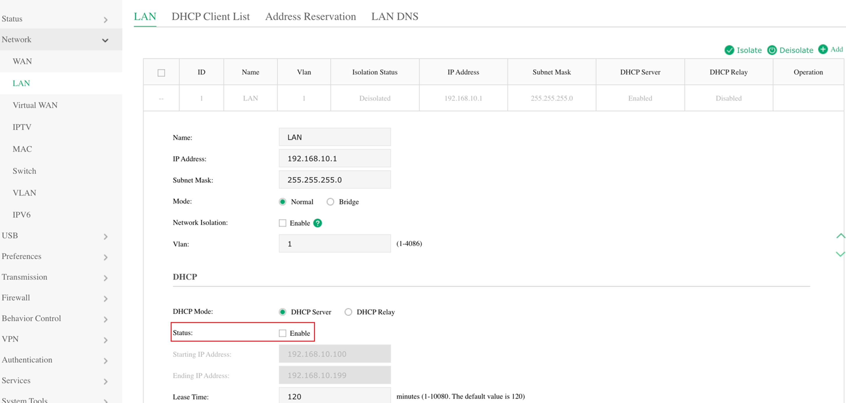
Disable the DHCP server function on ER605 in the Branch Office.
Go to VPN > IPsec > IPsec Policy and click Add.
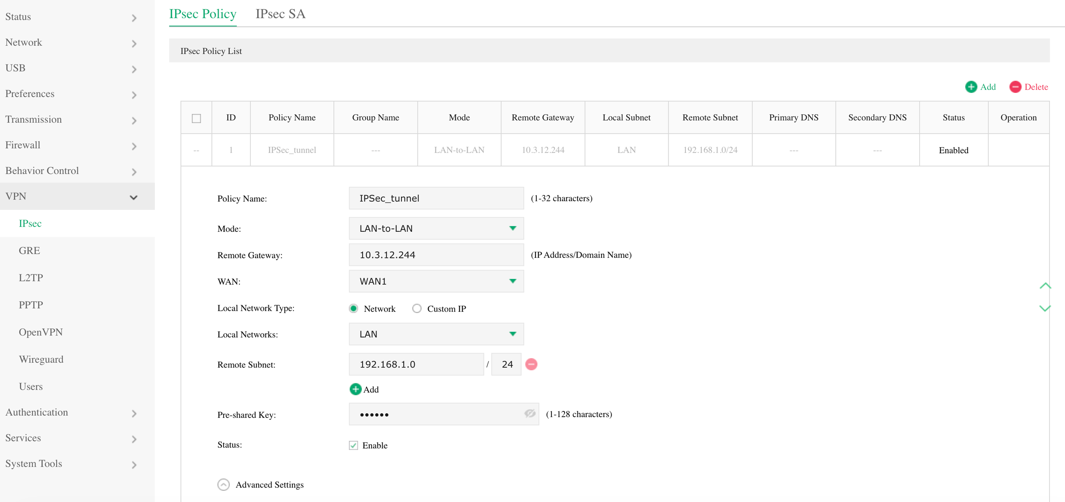
|
Remote Gateway |
Enter the WAN IP address of the Gateway in the Branch Office (10.3.12.244). |
|
WAN |
Select the WAN port on which the VPN tunnel will be established. |
|
Local Networks |
Select the networks in the headquarters (LAN), and the VPN policy will be applied to the selected networks. |
|
Remote Subnet |
Enter the IP address range of the LAN in the Branch Office (192.168.1.0/24). |
|
Pre-Shared Key |
Enter the Pre-Shared Key (PSK) that serves as an authentication key. The gateway in the headquarters and the Branch Office must use the same PSK for authentication. |
|
Status |
Check the box to enable the VPN tunnel. |
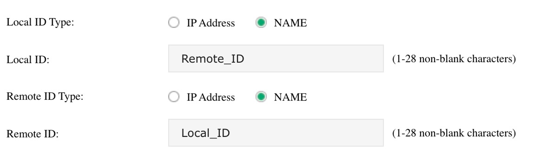
Note: If the router is behind a NAT device, make sure that UDP port 500 and UDP port 4500 are open on the NAT device, and set up the Local ID Type / Remote ID Type as Name in Phase-1 Settings.
For the Omada managed gateway in headquarters, go to Network Config > VPN Status > Site-to-Site VPN>IPsec and check the IPsec entries.

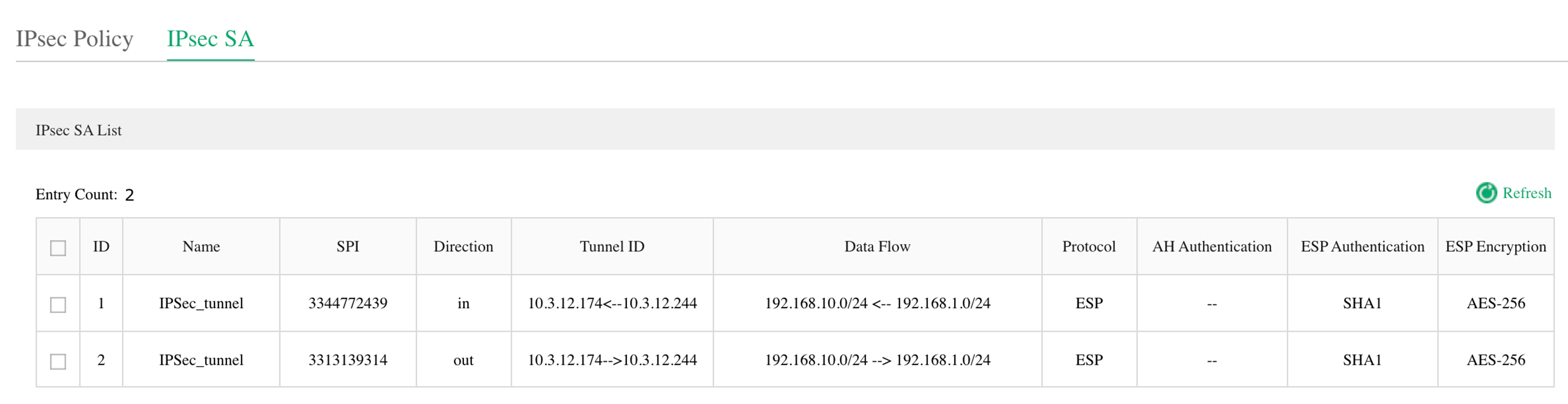
For ER605, go to VPN > IPsec > IPsec SA and check the IPsec SA entries. When corresponding entries are displayed in the tables, the VPN tunnel is successfully established.
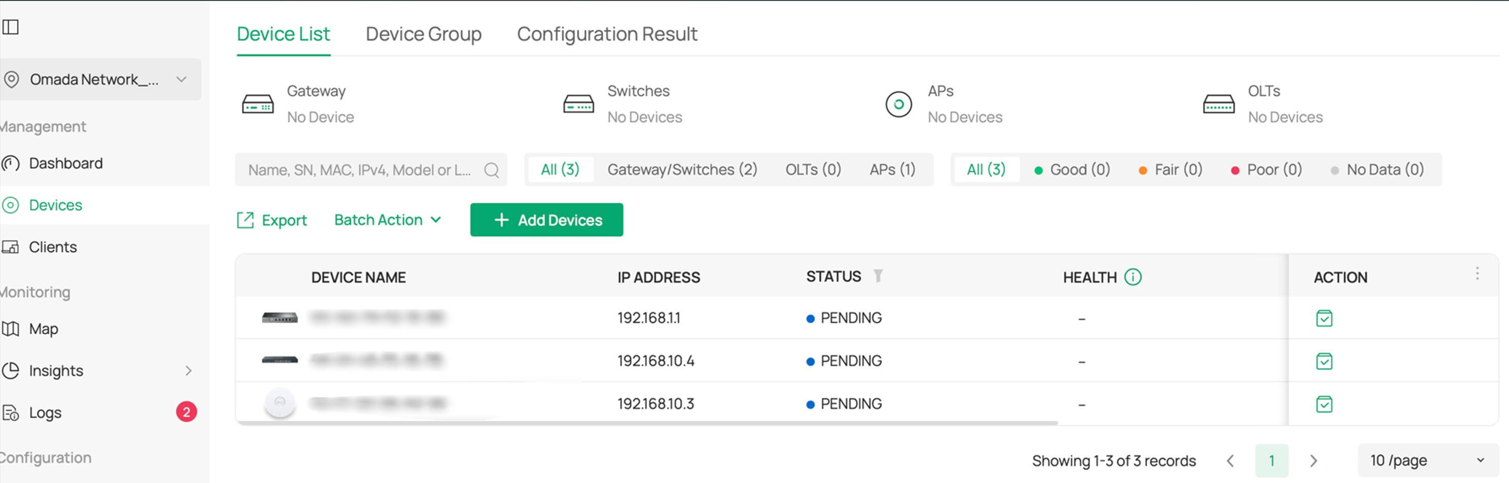
Step 3. Run the Omada Controller. The EAP will appear on Omada Controller’s “pending” list, which means you adopt and manage this EAP now shown in the list.
Conclusion
This article describes how to discover and adopt devices across subnets on the Omada Controller under two classic office network scenarios.
To learn more about each function and configuration, please visit Support Home to download or check the manual for your product.
QA
Q1: If devices are not across the Internet but only across different subnets, which steps in this document should be followed to discover and manage the devices?
A1: You can still use the Omada Discovery Utility/Inform URL/DHCP option 138 methods mentioned in Scenario 1 and enter the IP address of the Omada Controller.
