


Contents
Introduction
802.1Q VLANs allow administrators to logically separate a network into multiple broadcast domains using the same physical switch infrastructure. This guide explains how to create VLAN networks in Omada Controller and assign them to Omada switch ports as tagged or untagged networks based on the connected device and port purpose. Proper VLAN configuration helps isolate network traffic while allowing uplink ports to carry multiple VLANs between network devices.
Requirements
- Omada Agile, Access, Access Plus, Access Pro, Access Max, Aggregation, Campus Switch
- Omada Controller (Software Controller / Hardware Controller / Cloud-Based Controller, v6.0 and above)
Configuration
In this example, the third-party router has VLAN interfaces for VLANs 1, 10, and 20. Switch port G1/0/1 connects to the router and carries VLAN 1 as the native untagged network, while VLANs 10 and 20 are carried as tagged networks. Port G1/0/2 is configured with VLAN 10 as its native and untagged network, and port G1/0/3 is configured with VLAN 20 as its native and untagged network. This places each connected client into its assigned VLAN while allowing traffic from both VLANs to reach their respective gateway interfaces through the shared uplink.
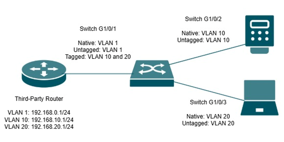
Note: VLANs separate traffic into different Layer 2 broadcast domains. If the router permits inter-VLAN routing, devices in VLAN 10 and VLAN 20 may still communicate. Configure ACL or firewall rules if communication between the VLANs must be blocked.
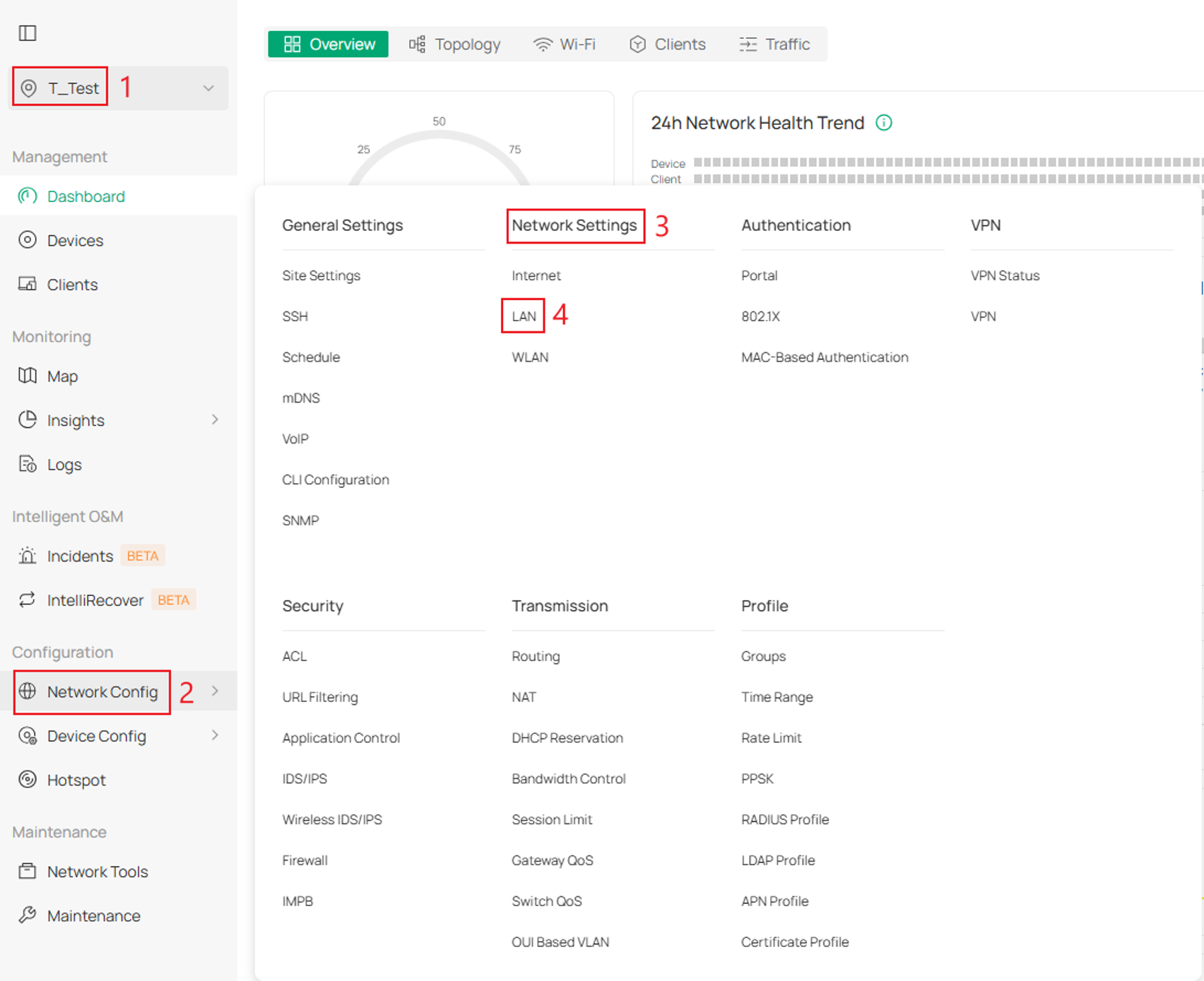
Step 1. Log into the Controller and navigate to your Site > Network Config > Network Settings > LAN.
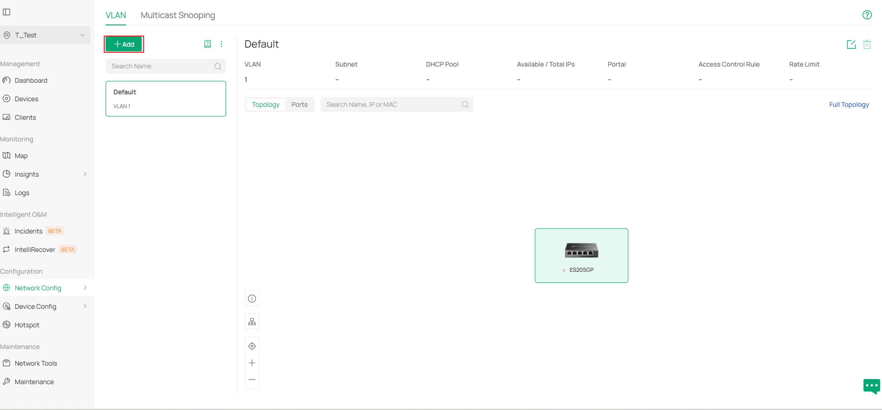
Step 2. Next, click Add to create a VLAN and fill in the parameters.
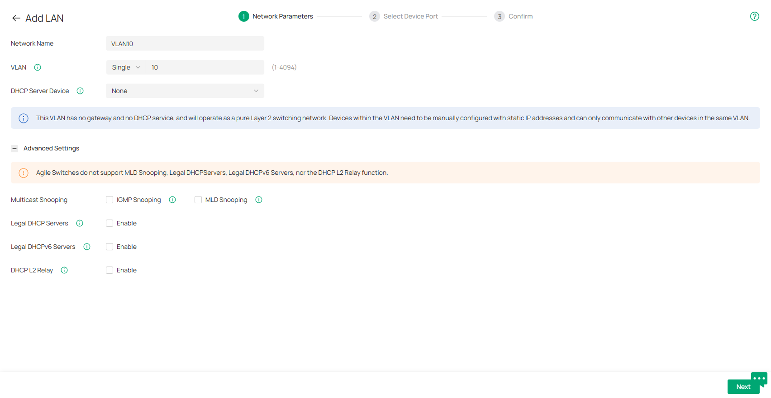
When creating an 802.1Q VLAN, make sure to switch the DHCP Server Device to None.
Click Next once complete.
Parameters:
Network Name: Enter a name to identify the network.
VLAN: Used to specify the VLAN ID. To create multiple VLANs at once, select Multiple.
DHCP Server Device: Select the DHCP Server device for the network.
Multicast Snooping: Select the Multicast Snooping function to be enabled. For more detailed configuration requirements, please visit the LAN-Multicast Snooping page.
IGMP Snooping: Click the checkbox to monitor IGMP (Internet Group Management Protocol) traffic and thereby manage multicast traffic.
MLD Snooping: Click the checkbox to monitor MLD (Multicast Listener Discovery) traffic and thereby manage IPv6 multicast traffic.
Legal DHCP Servers: Click the checkbox to specify legal DHCP servers for the network. With legal DHCP servers configured, Omada Gateways and Switches ensure that clients get IP addresses only from the DHCP servers specified here.
Legal DHCPv6 Servers: Click the checkbox to specify legal DHCPv6 servers for the network. With legal DHCPv6 servers configured, Omada Gateways and Switches ensure that clients get IPv6 addresses only from the DHCPv6 servers specified here.
DHCP L2 Relay: With DHCP L2 relay enabled, Omada switches configure the Option 82 field of the DHCP packets and transmit the packets in the LAN.
Step 3. Select the client-facing ports that should be configured as Access ports for the VLAN. Leave the router uplink unselected. Any unselected port that remains in Trunk mode will automatically carry the VLAN as tagged traffic.
Click Next once complete.
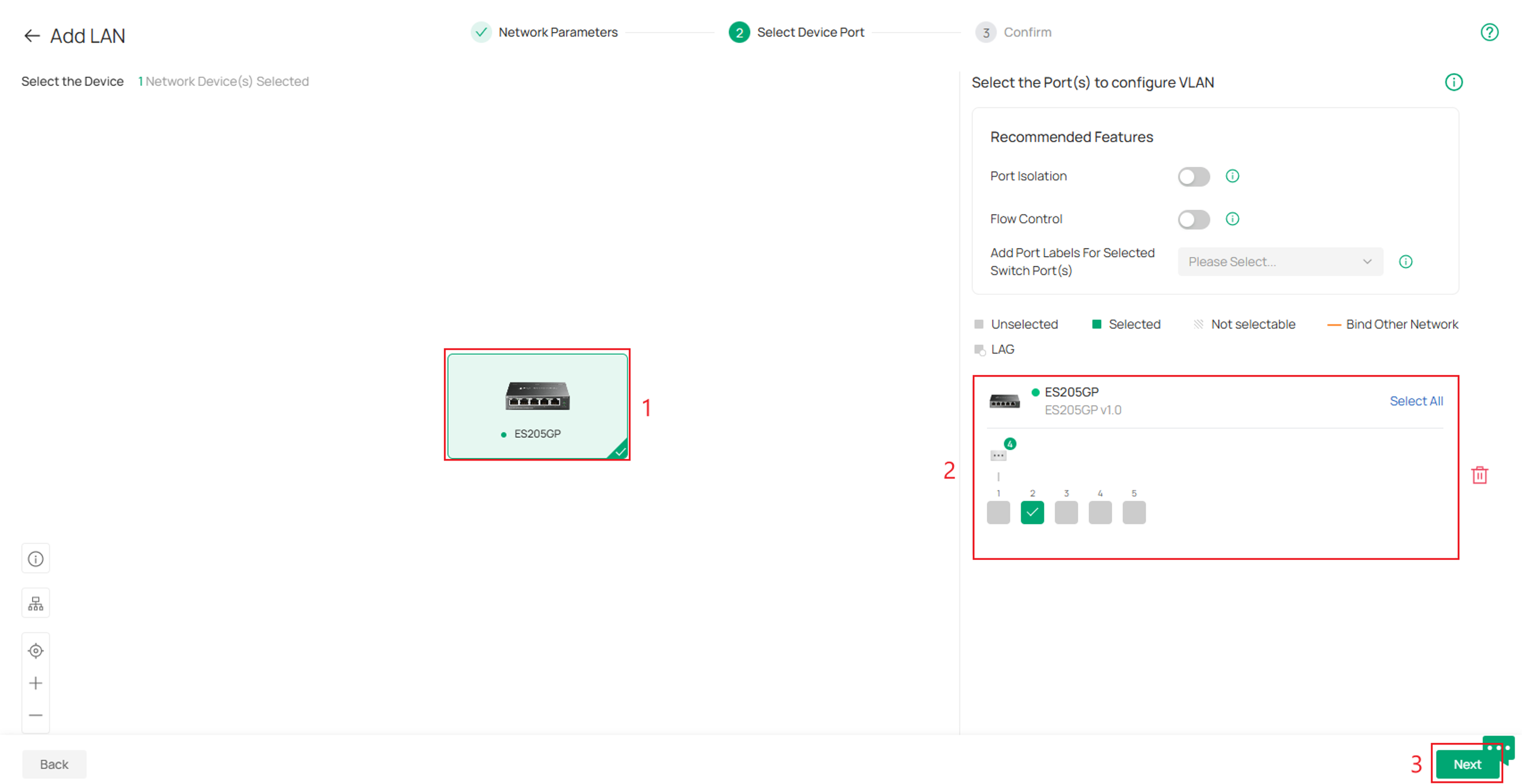
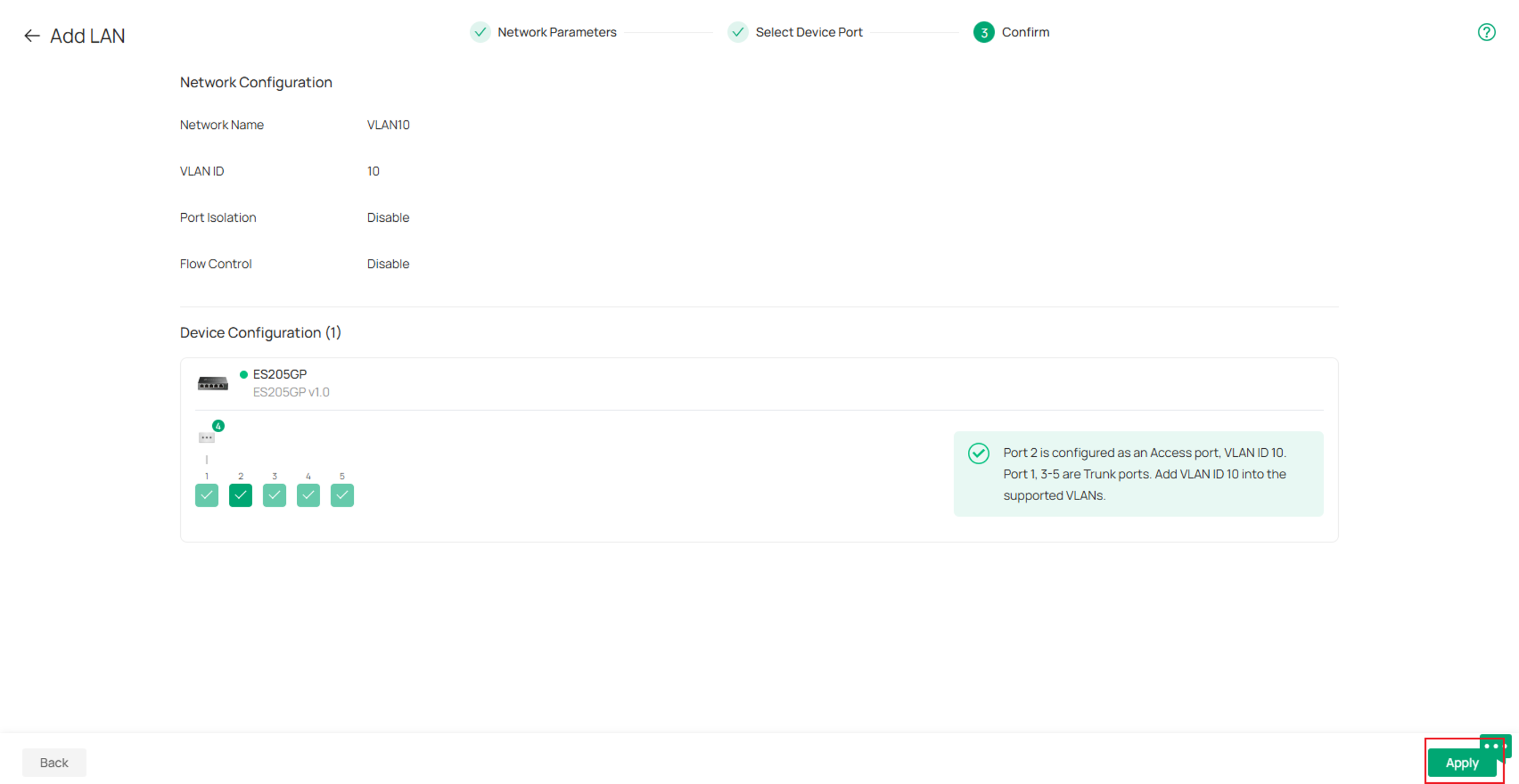
Step 4. Go over the VLANs configs on the next page and once complete click Apply.
Repeat steps 2-4 to create the remaining 802.1Q VLANs.
Verification
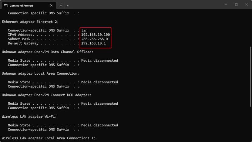
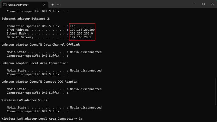
Connect a client to each configured access port and verify that it receives an IP address from the expected VLAN subnet.
Conclusion
IEEE 802.1Q VLANs allow an Omada switch to separate Layer 2 traffic while carrying multiple VLANs over a shared physical uplink. By configuring uplink ports with tagged VLANs and client-facing ports with the appropriate untagged VLAN, devices can be assigned to their intended networks. A VLAN-aware router or gateway is required to provide DHCP, internet access, and routing between VLANs when needed.
To learn more about each function and configuration, please visit Support Home to download or check the manual for your product.
QA
Q1: Why does a client lose network access after being assigned to a VLAN?
A1: Verify that the router has a corresponding VLAN interface and DHCP server, the VLAN is tagged on the router-to-switch uplink, and the client-facing switch port has the VLAN configured as native/untagged. Configuring the VLAN only on the switch does not provide the client with an IP address, default gateway, or internet access.
