


Contents
Introduction
OSPF (Open Shortest Path First) is a dynamic routing protocol that enables Layer 3 devices to automatically exchange routing information and select the best path for network traffic. By eliminating the need for manual route configuration, OSPF simplifies network management and adapts automatically to topology changes.
Omada Controller supports OSPFv2 for IPv4 on supported Omada switches, allowing dynamic routing to be centrally configured and managed. This article demonstrates how to configure OSPF on Omada switches in Controller Mode, including OSPF area configuration, network advertisement, route redistribution, and route verification.
Understanding OSPF
OSPFv2 is a link-state routing protocol designed for IPv4 networks. Unlike static routing, OSPF dynamically learns and updates routes by exchanging topology information with neighboring OSPF devices.
OSPF devices exchange link-state information through Link State Update (LSU) packets, which contain one or more Link State Advertisements (LSAs). Based on the received LSAs, each device builds a Link State Database (LSDB) that represents the network topology. Because all devices within the same OSPF domain maintain a synchronized LSDB, they have a consistent view of the network and can independently calculate optimal routes using the Dijkstra Shortest Path First (SPF) algorithm.
To improve scalability and reduce routing overhead, OSPF organizes networks into logical areas. Devices within the same area exchange detailed topology information, while summarized routing information is used for destinations in other areas.
Key OSPF area requirements include:
- Area IDs can be represented as either decimal values (0 to 4,294,967,295) or IPv4 dotted-decimal values (0.0.0.0 to 255.255.255.255).
- Area 0 (0.0.0.0) is the Backbone Area.
- All non-backbone areas must connect directly or indirectly to Area 0.
- Area IDs are 32-bit values.
Examples:
- Area 0 = 0.0.0.0
- Area 1 = 0.0.0.1
- Area 2 = 0.0.0.2
By default, OSPF advertises networks associated with OSPF-enabled interfaces. Route redistribution extends OSPF reachability by allowing additional routes, such as static routes, connected routes on non-OSPF interfaces, or routes learned through other routing protocols, to be advertised throughout the OSPF domain.
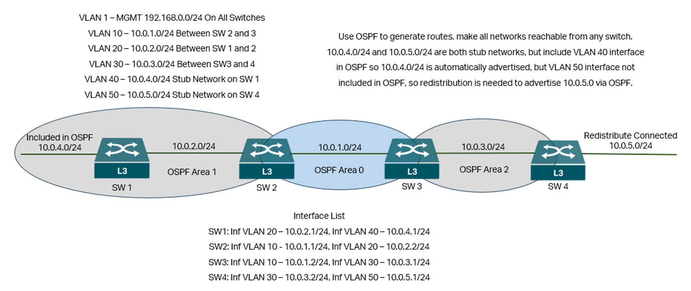
The example in this article uses a simple network topology to demonstrate how OSPF enables Omada switches to dynamically exchange routing information and provide end-to-end connectivity between all participating subnets.
Requirements
- Omada Campus Switch, Omada L3/Lite L3 Switch (SG5xxx/SX6xxx)
- Omada Controller v6.2 and above
Configuration
The configuration will be based on the topology below:
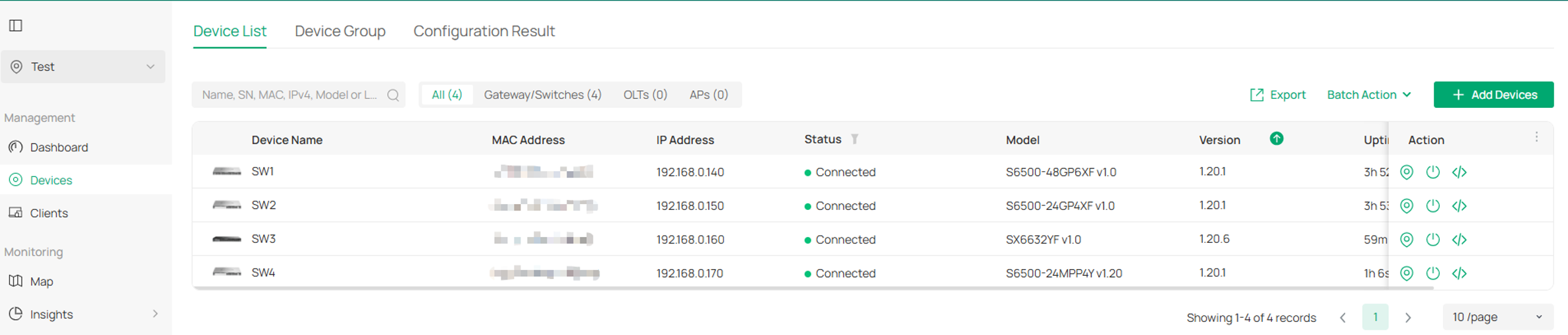
Step 1. Adopt all switches on Omada Controller. At this point, the VLAN 1 used for management is ready.
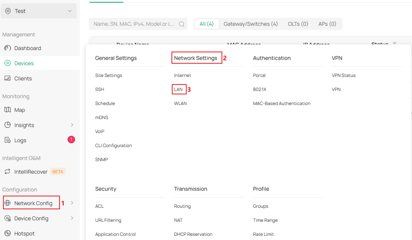
Step 2. Create the VLANs. Go to Network Config -> Network Settings -> LAN.
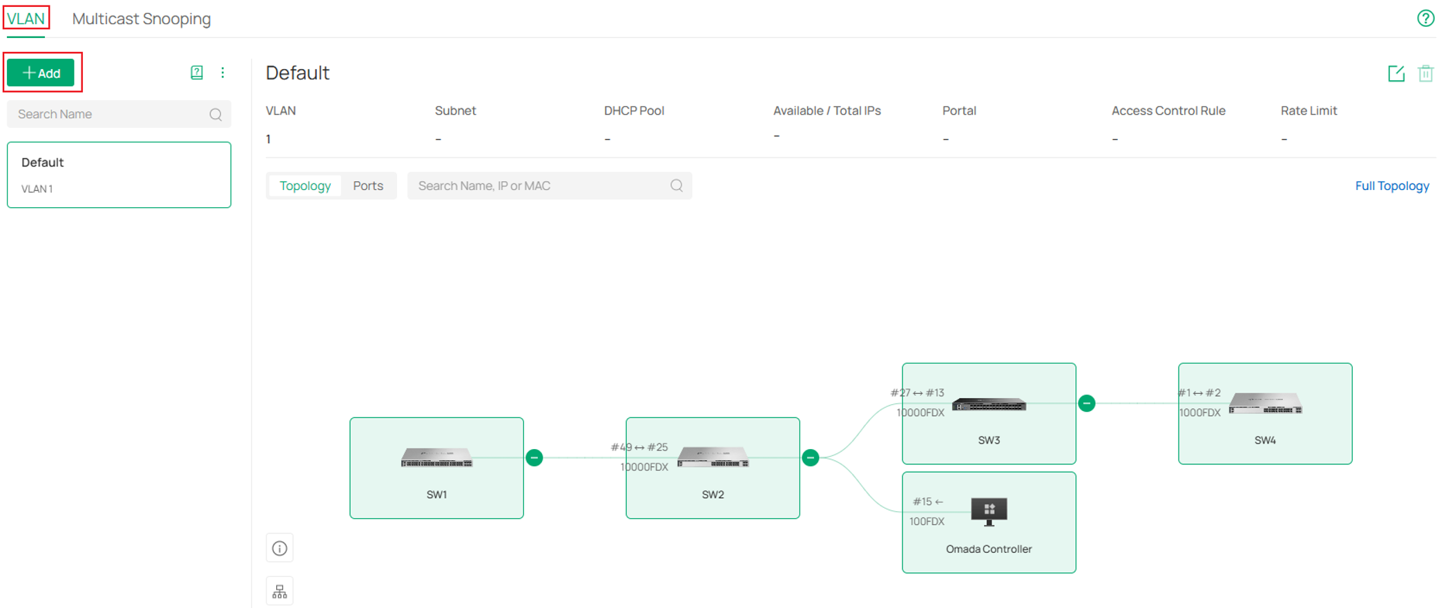
Click Add button in VLAN page.
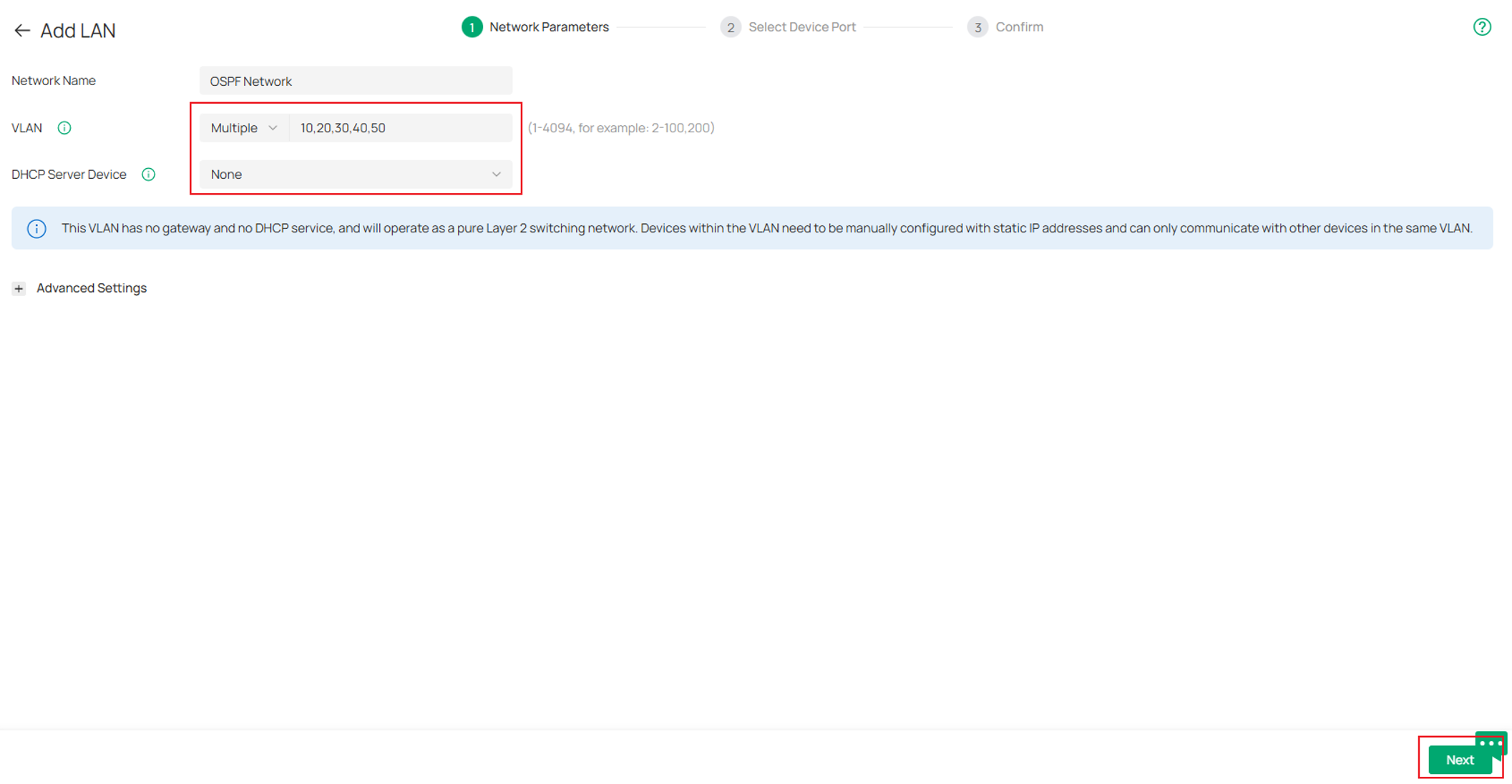
Name the VLANs, choose None for DHCP Server Device, Multiple for VLAN and enter the 5 VLANs prepared for OSPF, seperated with comma. Click Next to proceed.
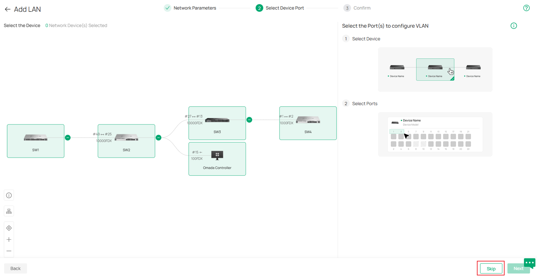
Click Skip in the next page, we will adjust port VLAN status in following steps.
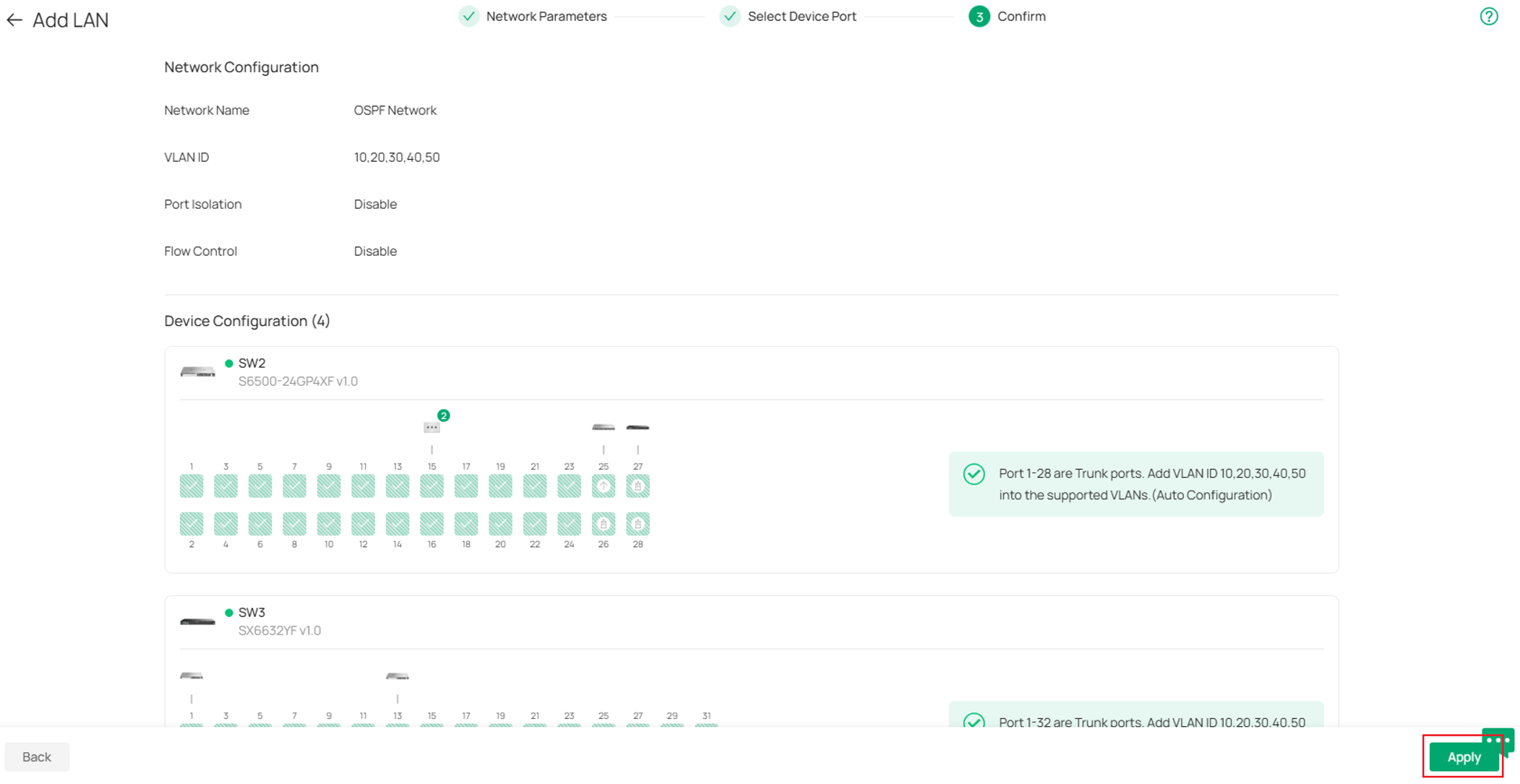
Confirm the info and click Apply to proceed.
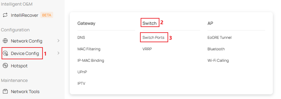
Step 3. Remove unused VLANs from switches cascade ports. Go to Device Config -> Switch -> Switch Ports.
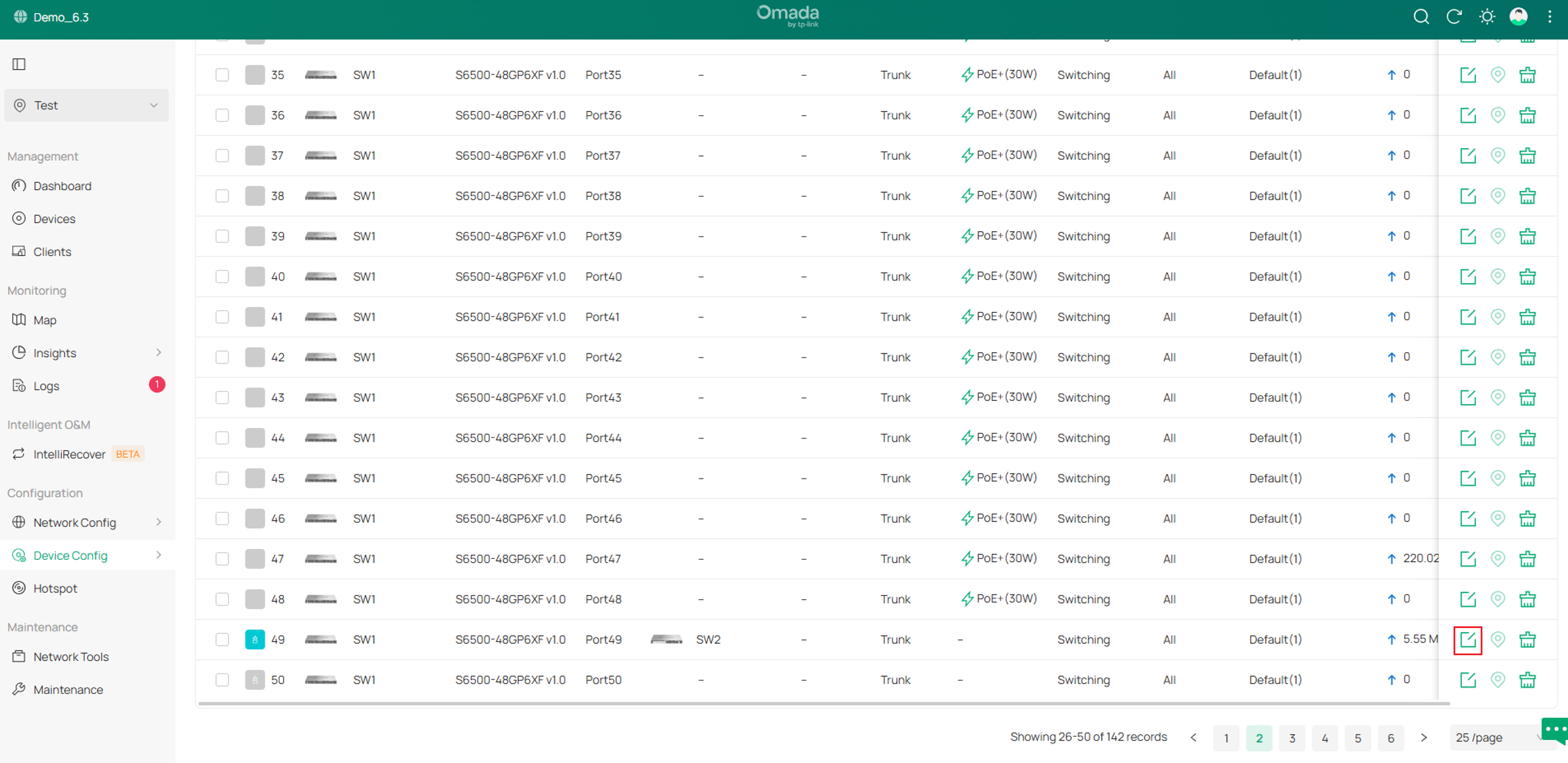
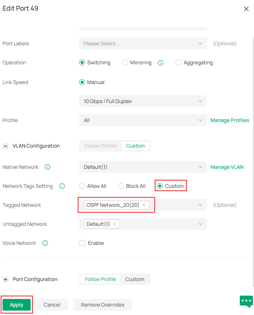
In VLAN Configuration section, choose Custom for Network Tags Setting, set VLAN 20 as Tagged Network only. Click Apply.
Change the port VLAN status for other cascade ports on all switches as needed, leave only the cascade VLANs between switches and the MGMT VLAN on cascade ports. To prevent clients receiving unnecessary OSPF traffic, user could also change accordingly on the downlink ports to remove any unnecessary VLANs.
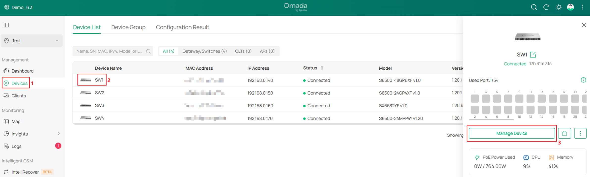
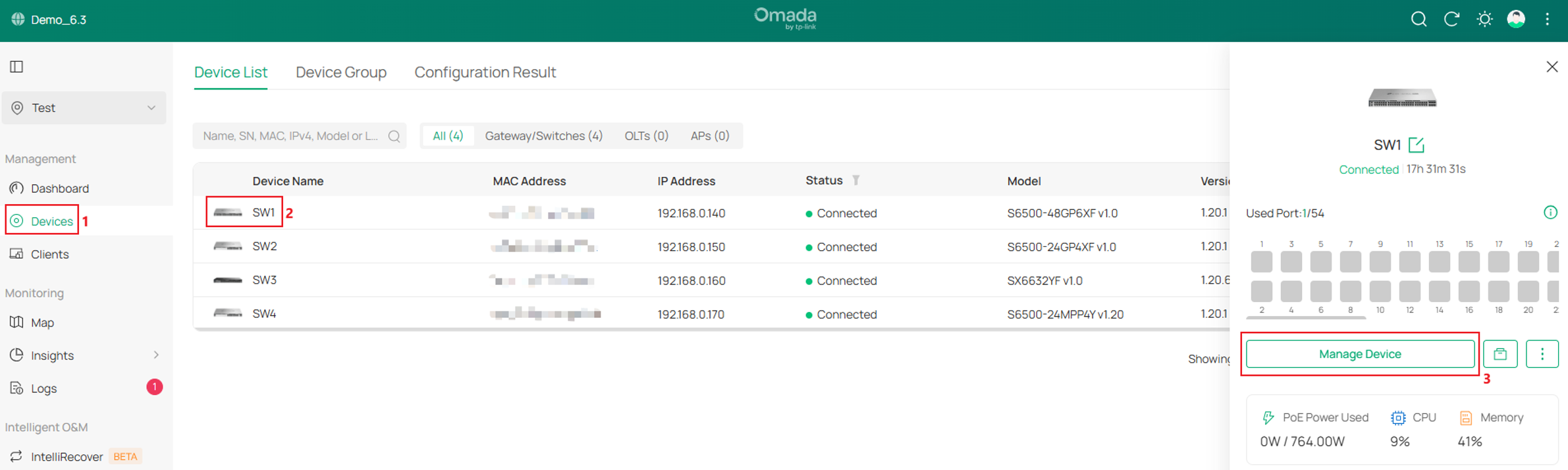
Step 4. Enable corresponding VLAN Interfaces on each switches and configure static IP addresses. Take SW1 as example, go to Devices, click SW1, go to Manage Device.
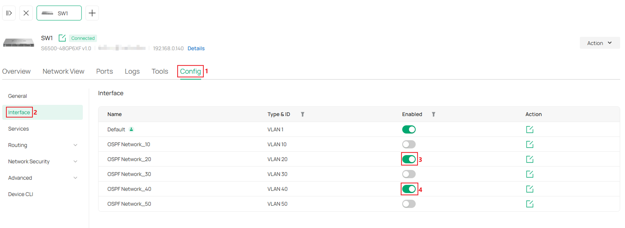
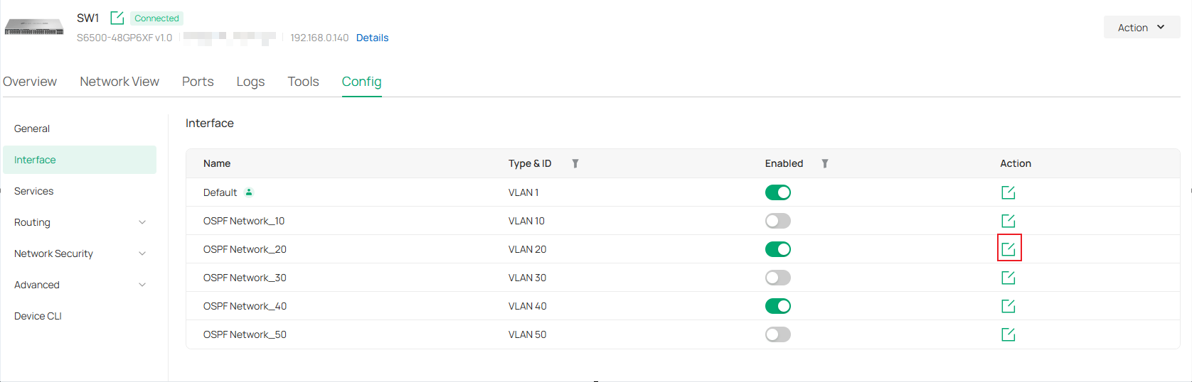
Go to Config -> Interface, tick to enable the interfaces for corresponding VLANs. For example, on SW1, enable interface for VLAN 20 and VLAN 40.
Take VLAN 20 interface as example, click the Edit button.
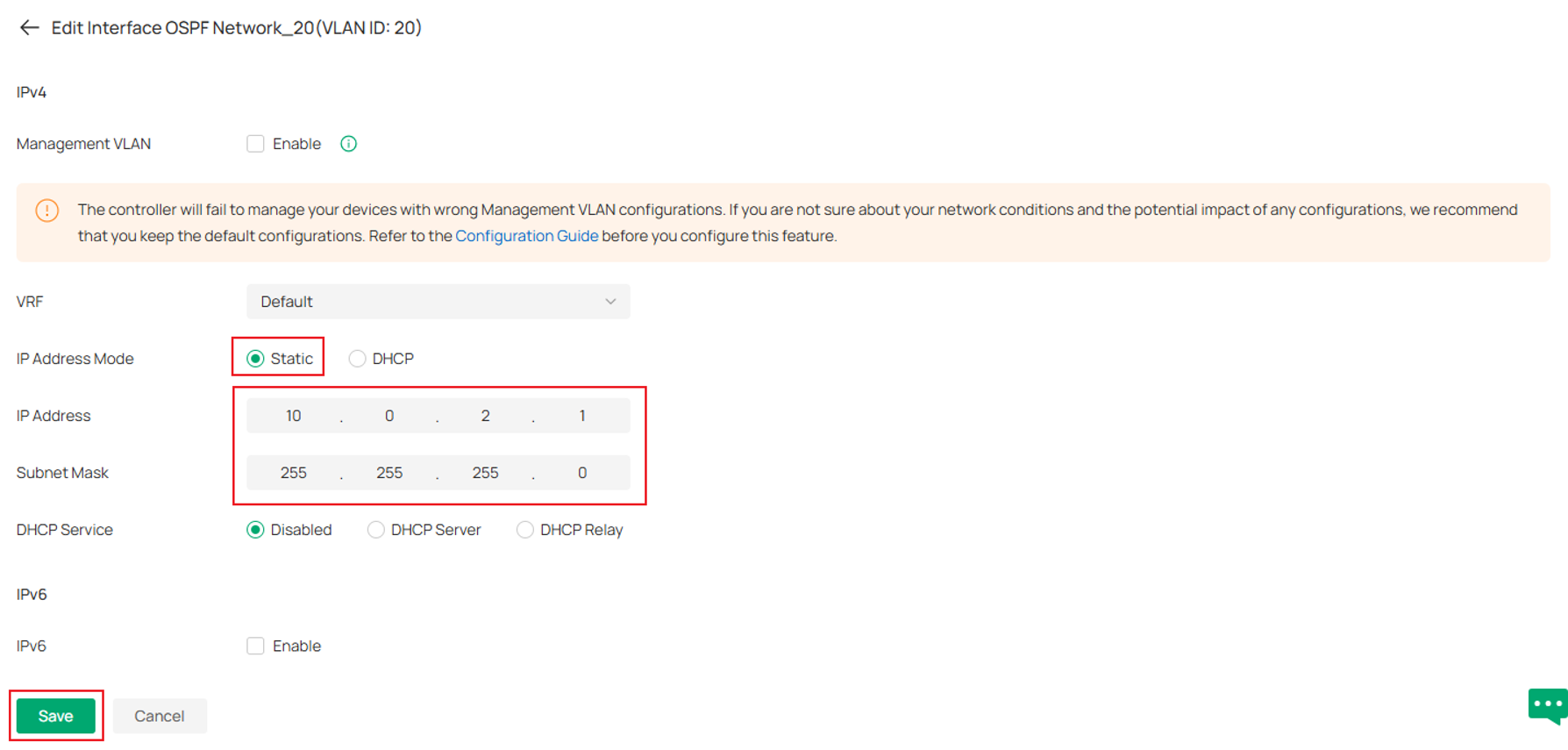
Set IP Address Mode as Static, enter the IP Address and Subnet Mask as introduced, click Save button to proceed.
Set all interfaces as planned on all switches same as described above.
Step 5. Create OSPF process and add networks on SW1. Go to Devices, click SW1, go to Manage Device.
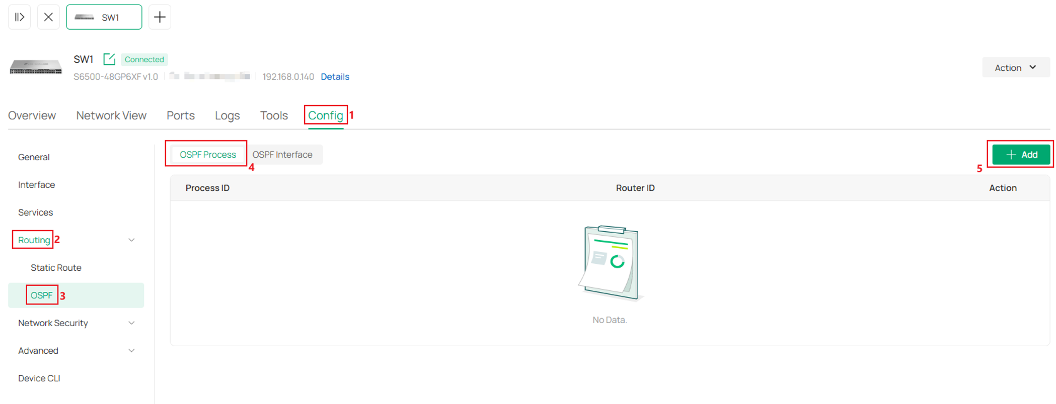
Go to Config -> Routing -> OSPF, in OSPF Process, click Add.
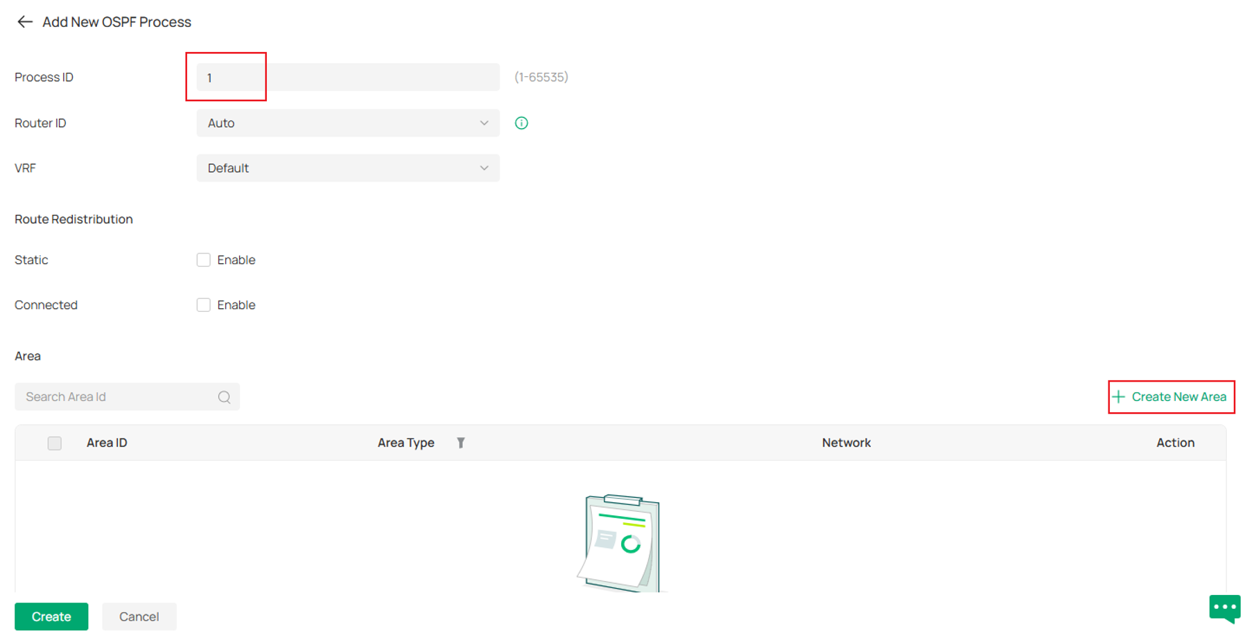
Enter a Process ID, please note that the Process ID doesn’t need to match on peer side, it’s only the marker locally as Omada Switches support running multiple OSPF processes at the same time. Then click Create New Area.
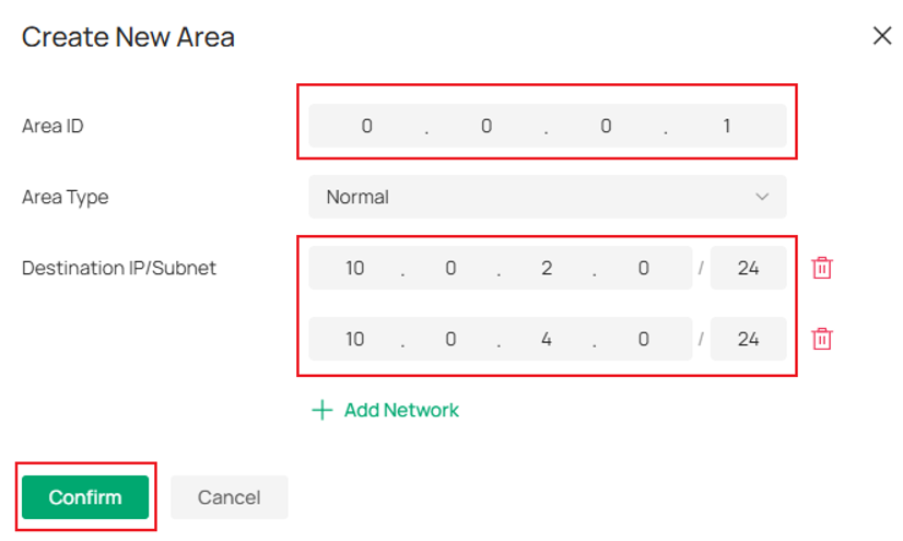
Enter the Area ID (Area 1 as planned), then click Add Network and add the VLAN 20, VLAN 40 networks to this OSPF process, putting them in Area 1. Click Confirm to proceed.
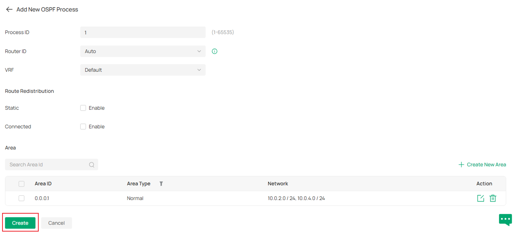
Review the details and click Create to finish creating OSPF process on SW1.
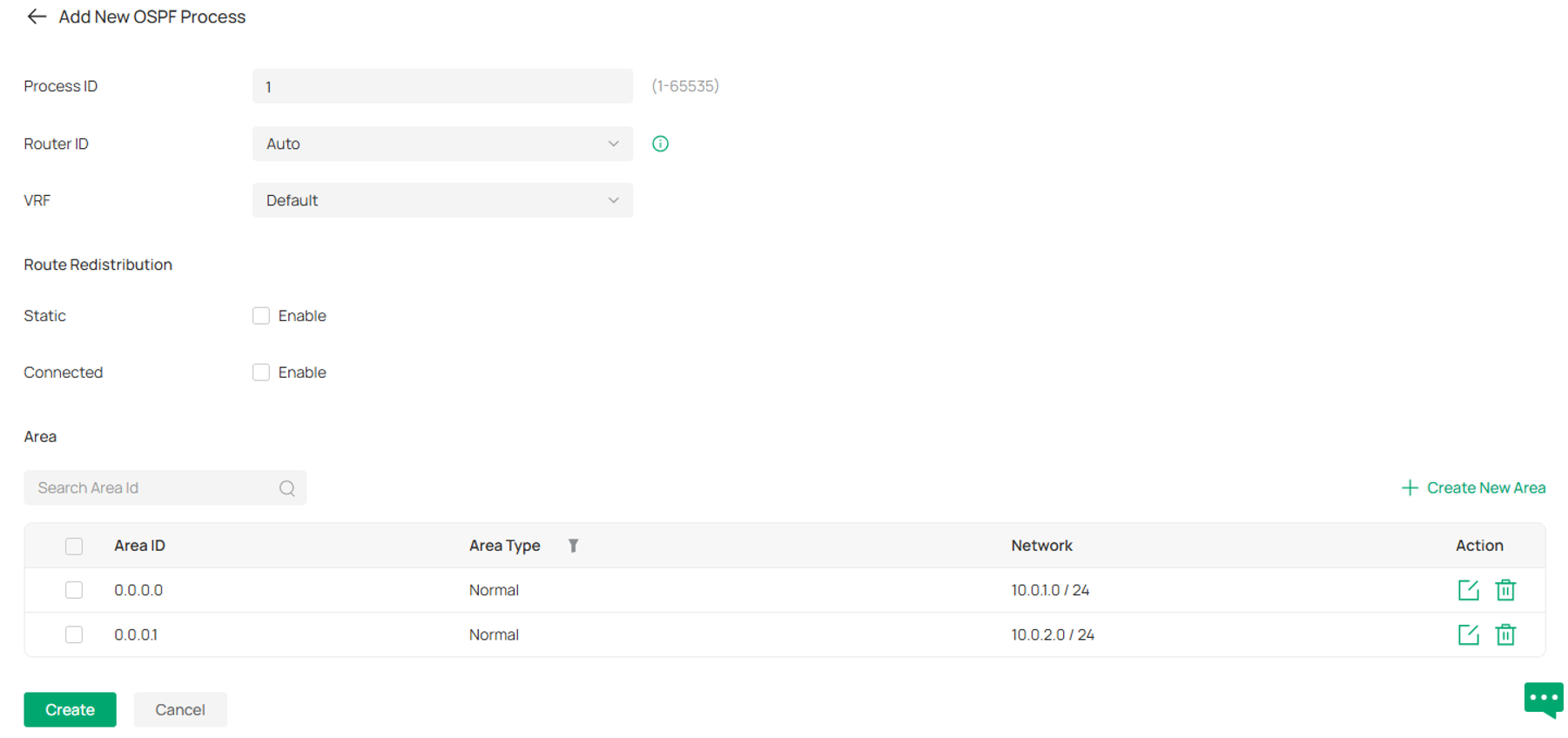
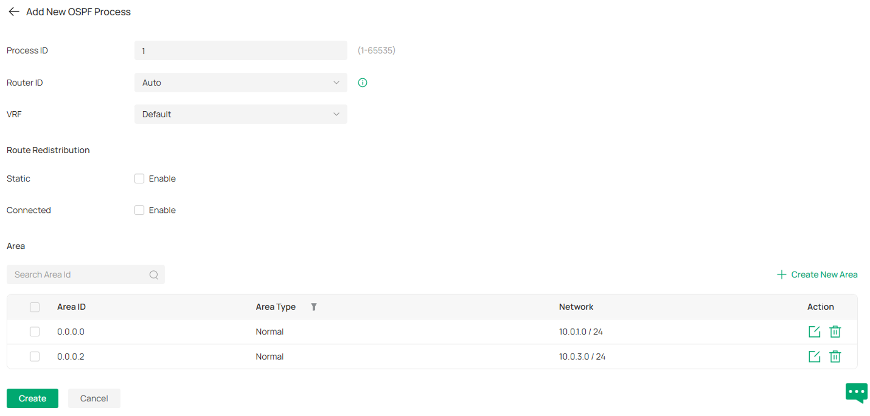
Step 6. Create OSPF process and related configuration on SW2, the steps are the same as introduced before, but according to example topology, we are adding two areas, Area 0 and 1 on SW2, for the networks, 10.0.1.0/24 is added to Area 0, 10.0.2.0/24 is added to Area 1.
Step 7. Create OSPF process and related configuration on SW3, the steps are the same as introduced before, but according to example topology, we are adding two areas, Area 0 and 2 on SW3, for the networks, 10.0.1.0/24 is added to Area 0, 10.0.3.0/24 is added to Area 2.
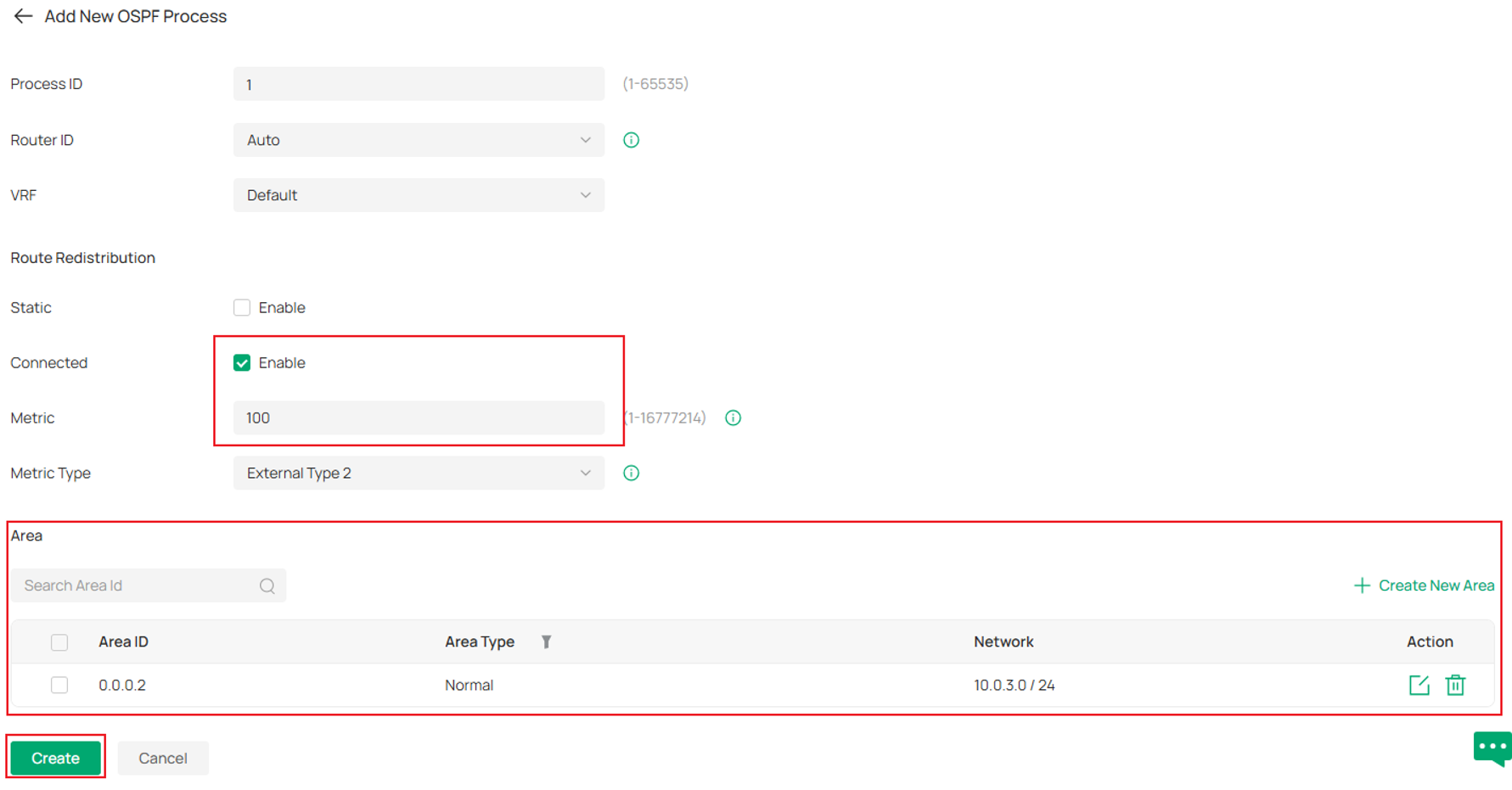
Step 8. Create OSPF process and related configuration on SW4, the steps are the same as introduced before, but according to example topology, we are adding only Area 2, the network 10.0.3.0/24 is added to Area 2 and the network 10.0.5.0/24 is not added to OSPF, but we will redistribute it to make it also advertised in OSPF. After adding Area 2 and 10.0.3.0/24 to it, tick the Enable for Connected in Route Redistribution, as 10.0.5.0/24 is a Connected Route generated by interface VLAN 50 we created. Enter the Metric for it. Review the details, click Create to finish the configuration.
The OSPF configuration on all four switches are finished as shown above.
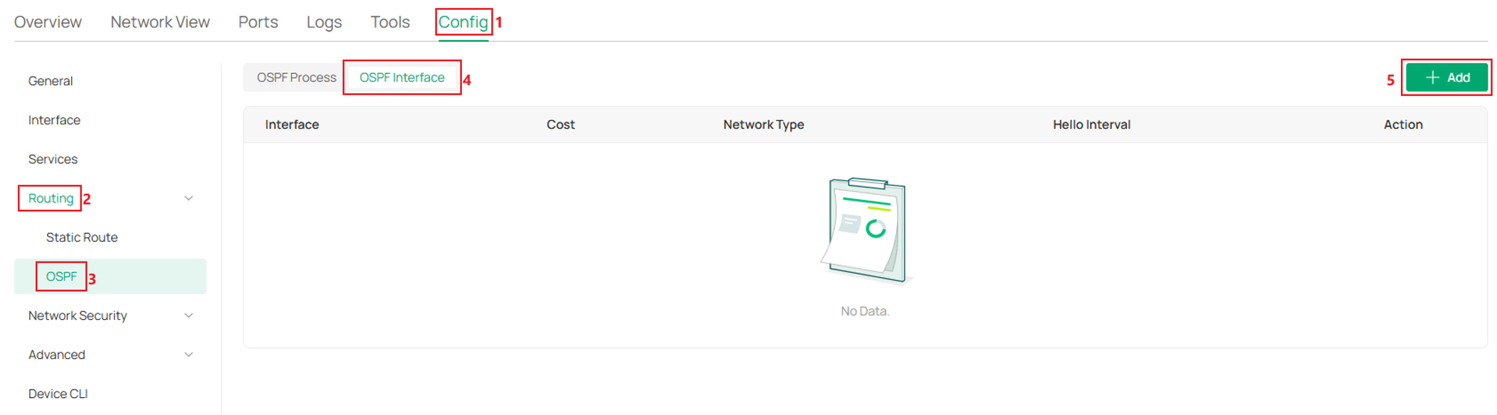
Step 9. (Optional) To change or configure OSPF interface network type, interface cost, hello interval, dead interval, OSPF authentication, go to Config -> Routing -> OSPF -> OSPF Interface, click Add.
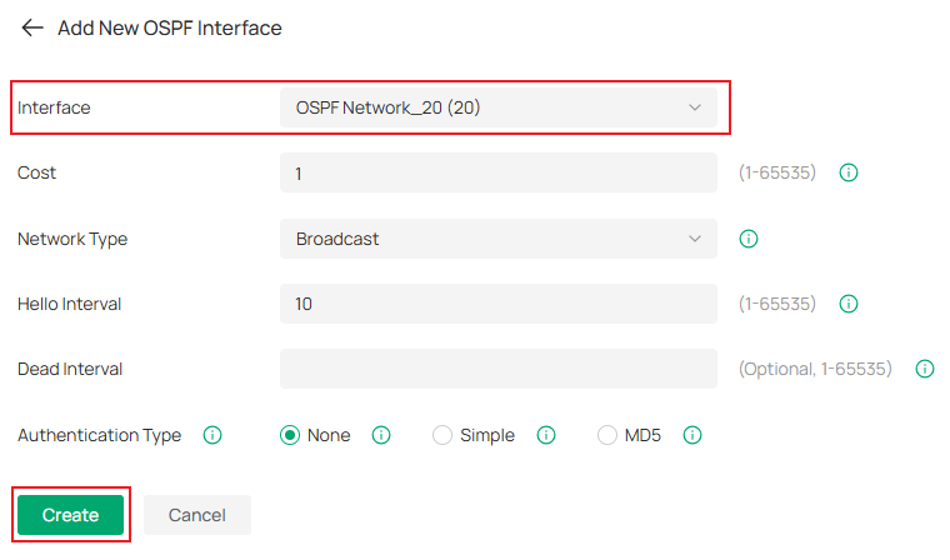
Select the interface which needs to be modified, then configure as needed and click Create to save the config.
Verification
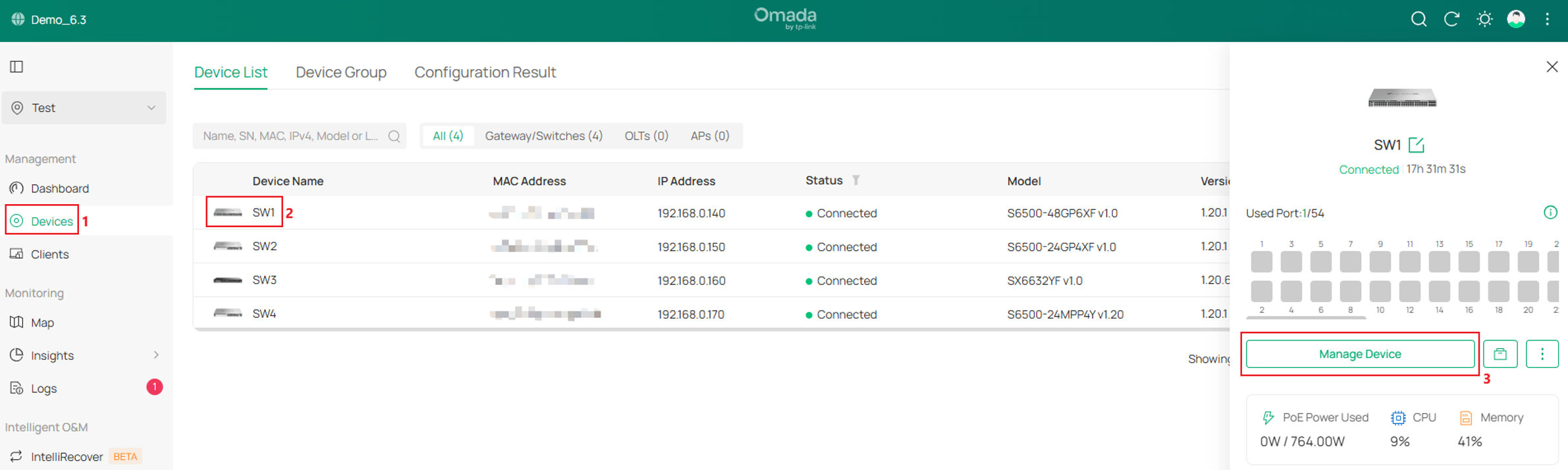
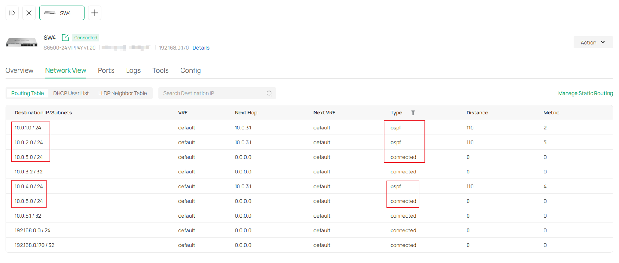
On each switch, check the routing table to see if all subnets created are learnt via OSPF. Take SW1 as example, go to Devices, click SW1, go to Manage Device.
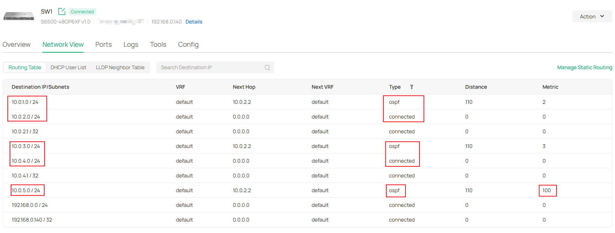
Go to Network View -> Routing Table. For SW1, 10.0.2.0/24 and 10.0.4.0/24 are connected routes, and the subnets attached on other switches, 10.0.1.0/24, 10.0.3.0/24 and 10.0.5.0/24 are learnt via OSPF, as their Type are marked as ospf. As 10.0.5.0/24 is the redistributed route configured on SW4 with Metric set to 100, its Metric is also shown as 100 in the Routing Table of SW1.
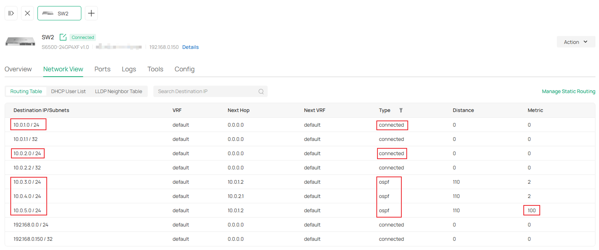
For SW2:
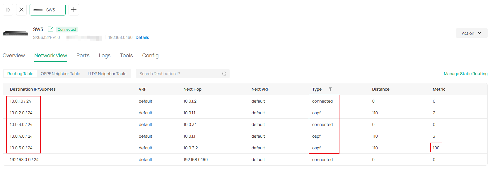
For SW3:
For SW4:
Conclusion
In this article, we have introduced the configuration process for OSPF with a simple topology for Omada Switches adopted on Omada Controller.
To learn more about each function and configuration, please visit Support Home to download or check the manual for your product.
