


Contents
Introduction
In enterprise deployments, network devices often need to adapt to different cabling conditions, uplink media types, and bandwidth requirements. To provide greater deployment flexibility, supported devices can dynamically determine and switch their uplink interfaces, enabling the same physical port to serve either upstream or downstream connectivity based on the network topology. Because uplink traffic carries management and service data, dynamic uplink operation is closely associated with Port VLAN settings, which define how traffic is tagged and forwarded across the network. In addition, when multiple Ethernet links are combined through Link Aggregation (LAG), uplink selection behavior and VLAN configuration must be coordinated to ensure proper traffic forwarding, bandwidth utilization, and link redundancy. Understanding the relationship among these features helps administrators deploy devices more efficiently while maintaining stable network access and management connectivity.
Requirements
-
Omada Controller v6.3 or above.
- The following model of Omada AP:
|
Model |
Hardware Version |
Firmware Version |
|
AP9788 |
1.0 |
1.0.0 or above |
Configuration
This section describes how to configure dynamic uplink port settings in both Controller and Standalone modes, including deployment scenarios with and without Link Aggregation (LAG).
In Controller Mode
Step 1. Discover and adopt the device in Omada Controller.
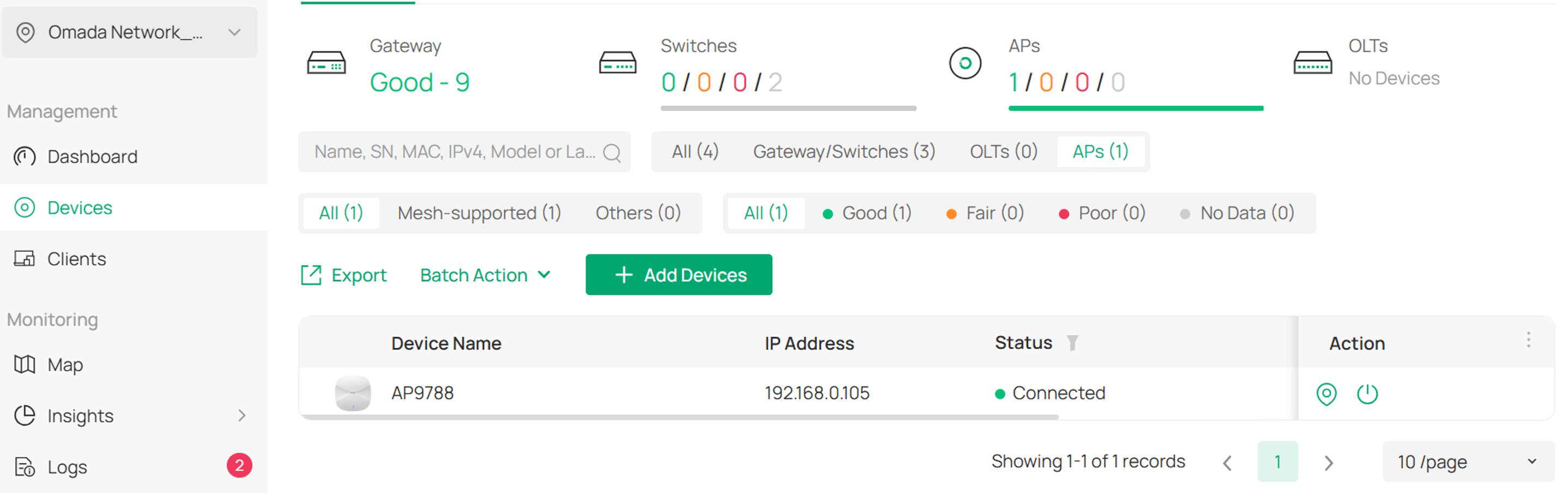
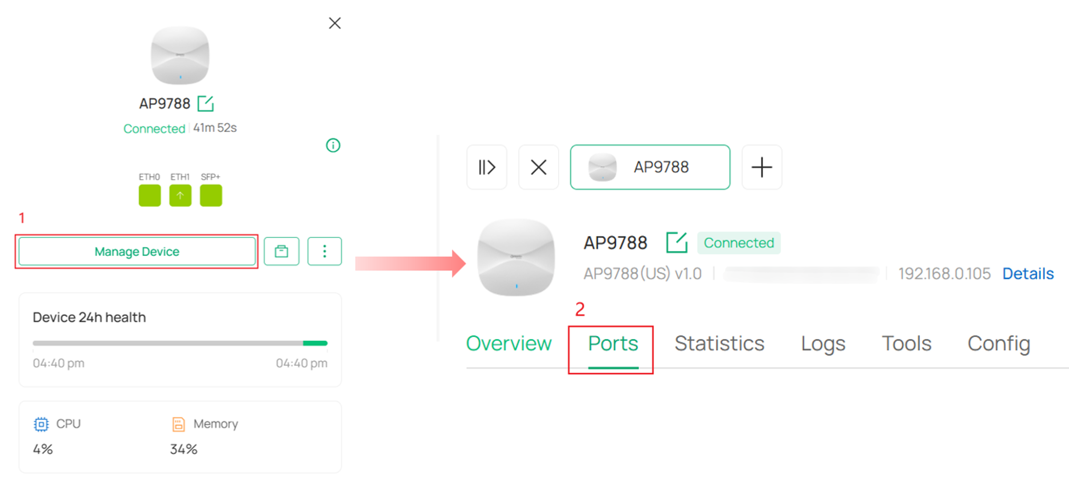
Step 2. Go to Manage Device > Ports in device private management page.
Step 3. You can configure uplink port settings on the Ports page. By default, the Uplink Port option is set to Auto.
Configuring an Uplink Port without LAG:
The AP9788 is equipped with three wired interfaces: ETH0, ETH1, and SFP+. To simplify deployment, the device automatically selects an uplink port when multiple interfaces are active.
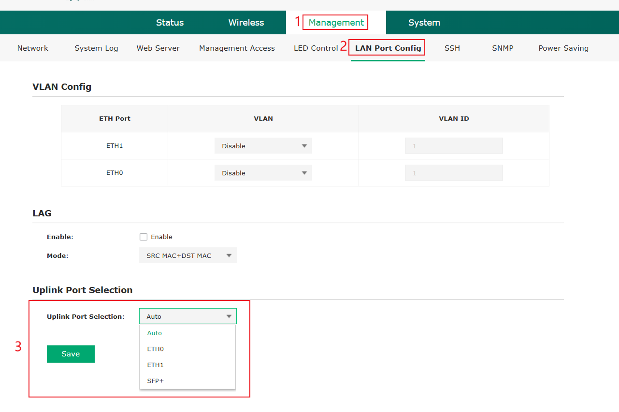
In Auto mode, the uplink selection priority is SFP+ > ETH1 > ETH0.
If the uplink port is manually specified as SFP+, ETH1, or ETH0, the selected interface is treated as the logical uplink port. 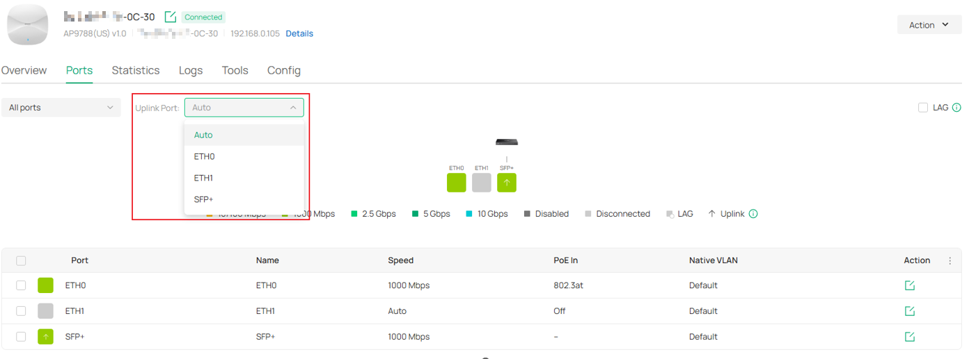
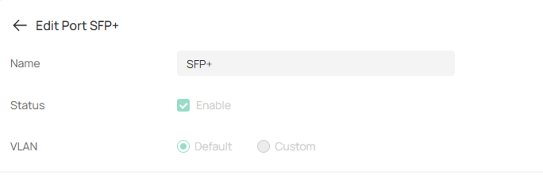
To prevent management connectivity issues caused by misconfiguration, Port Status and Port VLAN settings cannot be modified on the logical uplink port. These settings are configurable only on downlink ports.
In Omada Controller v6.3 or above, the uplink port indicator represents the physical uplink port, which is the port currently connected to the upstream network device. This behavior is consistent with the network topology view, and the physical uplink port itself cannot be manually configured.

The port that can be manually selected is the logical uplink port. The logical uplink port and the physical uplink port are determined independently and may not necessarily be the same interface.
After a logical uplink port is specified, Port VLAN settings become available for downlink ports. Certain features also rely on the logical uplink port to function correctly. For example, multicast rate limiting is applied only to traffic received through the logical uplink port.
Therefore, it is important to distinguish between the physical uplink port, which is used for actual upstream connectivity, and the logical uplink port, which serves as the reference port for feature configuration and traffic processing.
Configuring an Uplink Port with LAG:
LAG increases available bandwidth while providing link redundancy, ensuring higher network performance and reliability.
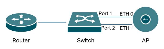
Note: It is strongly recommended to only connect Port 1 to ETH0 before completing all configurations. Because the two links without LAG configured will cause a loop problem, which may reduce the performance of the switch and even lead to network paralysis.
You can enable and configure Link Aggregation (LAG) from the upper-left corner of the Port page. For most deployments, the default LAG mode is recommended.
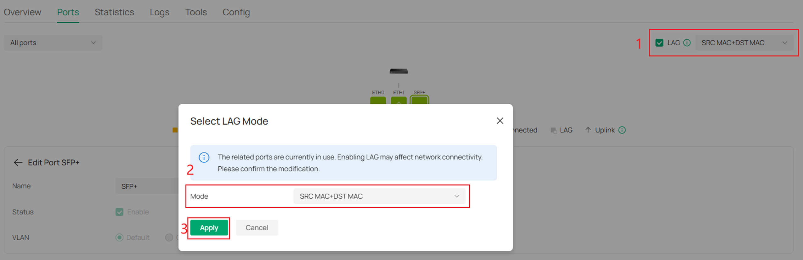
|
Mode |
Description |
|
SRC MAC + DST MAC |
Traffic is distributed based on both the source and destination MAC addresses, providing the most balanced load distribution across LAG member ports. |
|
DST MAC |
Traffic is distributed based on the destination MAC address. Frames destined for the same device are forwarded through the same LAG member port. |
|
SRC MAC |
Traffic is distributed based on the source MAC address. Frames originating from the same device are forwarded through the same LAG member port. |
Before enabling LAG, set the Uplink Port to Auto. After LAG is enabled, ETH0 and ETH1 are combined into a single logical uplink port. An "L" badge is displayed on the lower-right corner of the member ports to indicate that they belong to the LAG group.
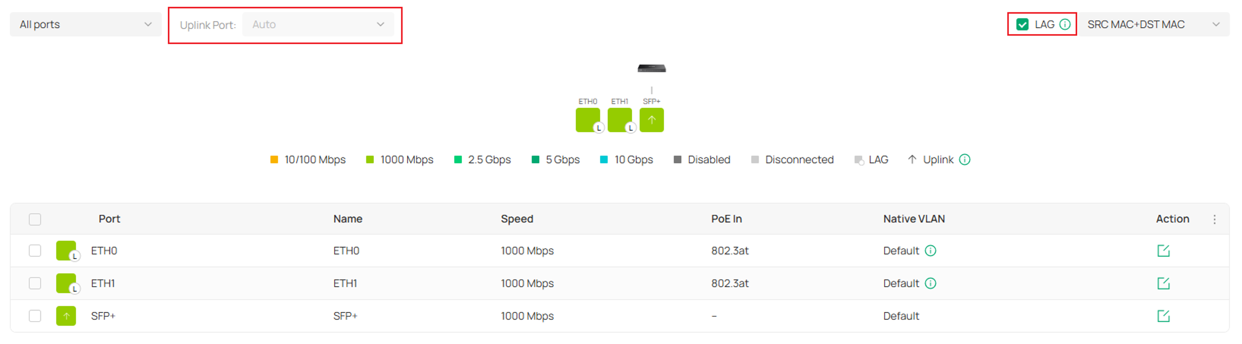
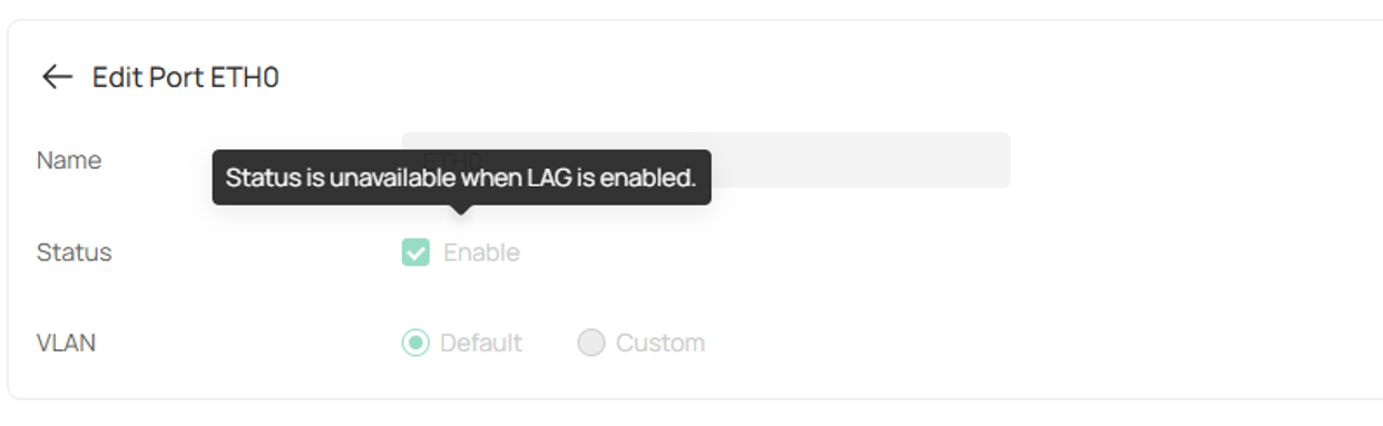
When LAG is enabled, Port VLAN configuration is no longer available for ETH0 and ETH1, because VLAN settings are managed at the logical aggregated link level rather than on individual member ports.
In Standalone Mode
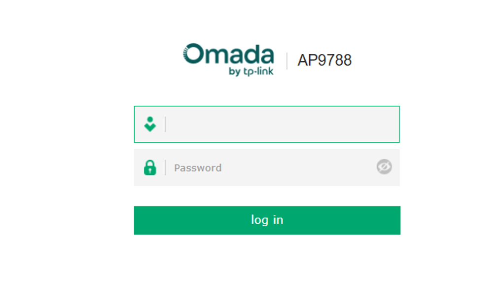
Step 1. Enter the AP's IP address in a web browser to access the web management interface. Then either complete the Quick Setup process or log in using the device's username and password.
Step 2. Navigate to Management > LAN Port Config > Uplink Port Selection and select the uplink logical port. The default setting is Auto, with the following port priority: SFP+ > ETH1 > ETH0.
Please note that Link Aggregation cannot be enabled when a specific uplink port is selected. Please clear the uplink port selection to use Link Aggregation.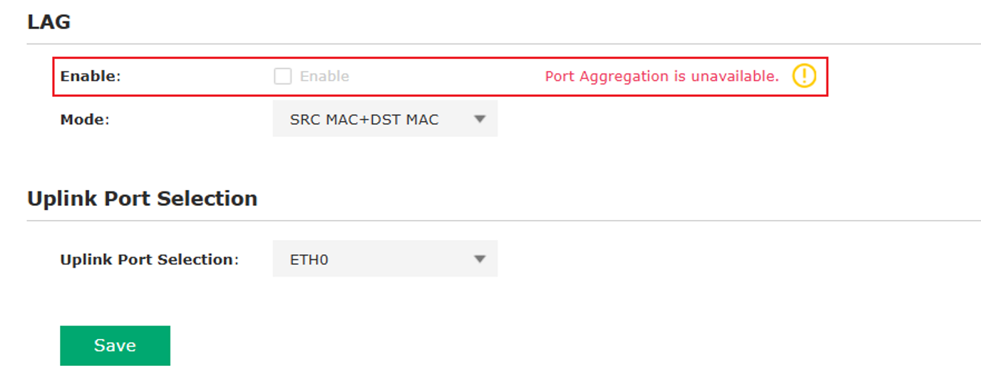
Conclusion
You have successfully configured Dynamic Uplink Port on an Omada Campus AP in either Controller Mode or Standalone Mode. By understanding the difference between physical uplink ports and logical uplink ports, you can deploy the AP more flexibly while maintaining reliable management and traffic forwarding.
For deployments that require higher bandwidth and link redundancy, Link Aggregation (LAG) can combine multiple Ethernet interfaces into a single logical uplink. Proper uplink selection and VLAN configuration help ensure stable network operation and optimal performance.
To learn more about each function and configuration, please visit Support Home to download or check the manual for your product.
QA
Q1: Why can't I modify the Status or Port VLAN settings of a port?
A1: The port is currently configured as the logical uplink port, so Status and Port VLAN settings are unavailable.
Q2: Why can't I enable Link Aggregation (LAG)?
A2: Before enabling LAG, make sure the Uplink Port is set to Auto. LAG cannot be configured when a specific uplink port is selected.
Q3: Why can't I change the Uplink Port setting?
A3: If LAG is enabled, ETH0 and ETH1 are automatically aggregated into a logical uplink port, and the Uplink Port option becomes unavailable. Disable LAG first to modify the uplink port selection.
