


Contents
Configuration in Standalone mode
Configuration in Controller mode
Introduction
Port Isolation lets you block traffic between specific ports so you can protect your network and control how devices communicate. In standalone mode, you can set flexible isolation rules; however, in controller mode, the feature is simplified for compatibility—when you enable it on a port, that port becomes isolated and cannot communicate with any other isolated port.
Requirements
- Omada Access, Access Plus, Access Pro, Access Max, Aggregation, Campus Switch
- Omada Controller (Software Controller / Hardware Controller / Cloud Based Controller, V6.0 and above)
Configuration
The following sections provide separate instructions for configuration in standalone mode and controller mode.
Configuration in Standalone mode
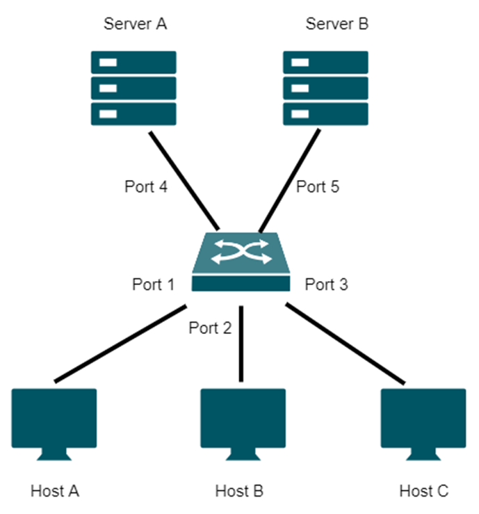
Here is an application example for Port Isolation. Hosts A, B, and C are connected to ports 1, 2, and 3, respectively. Server A and server B are connected to port 4, and port 5, respectively. It is required that Hosts A, B and C cannot communicate with each other; Host A can visit both server A and server B, while host B and host C can only visit server A.
To meet the requirement, you can define a different Forwarding Port List for each port. Note that since communications are bidirectional, if you want two ports communicate normally, they need to be in each other’s forwarding lists.
|
Port |
Forwarding Port List |
|
Port 1 |
Port 4, 5 |
|
Port 2 |
Port 4 |
|
Port 3 |
Port 4 |
|
Port 4 |
Port 1, 2, 3 |
|
Port 5 |
Port 1 |
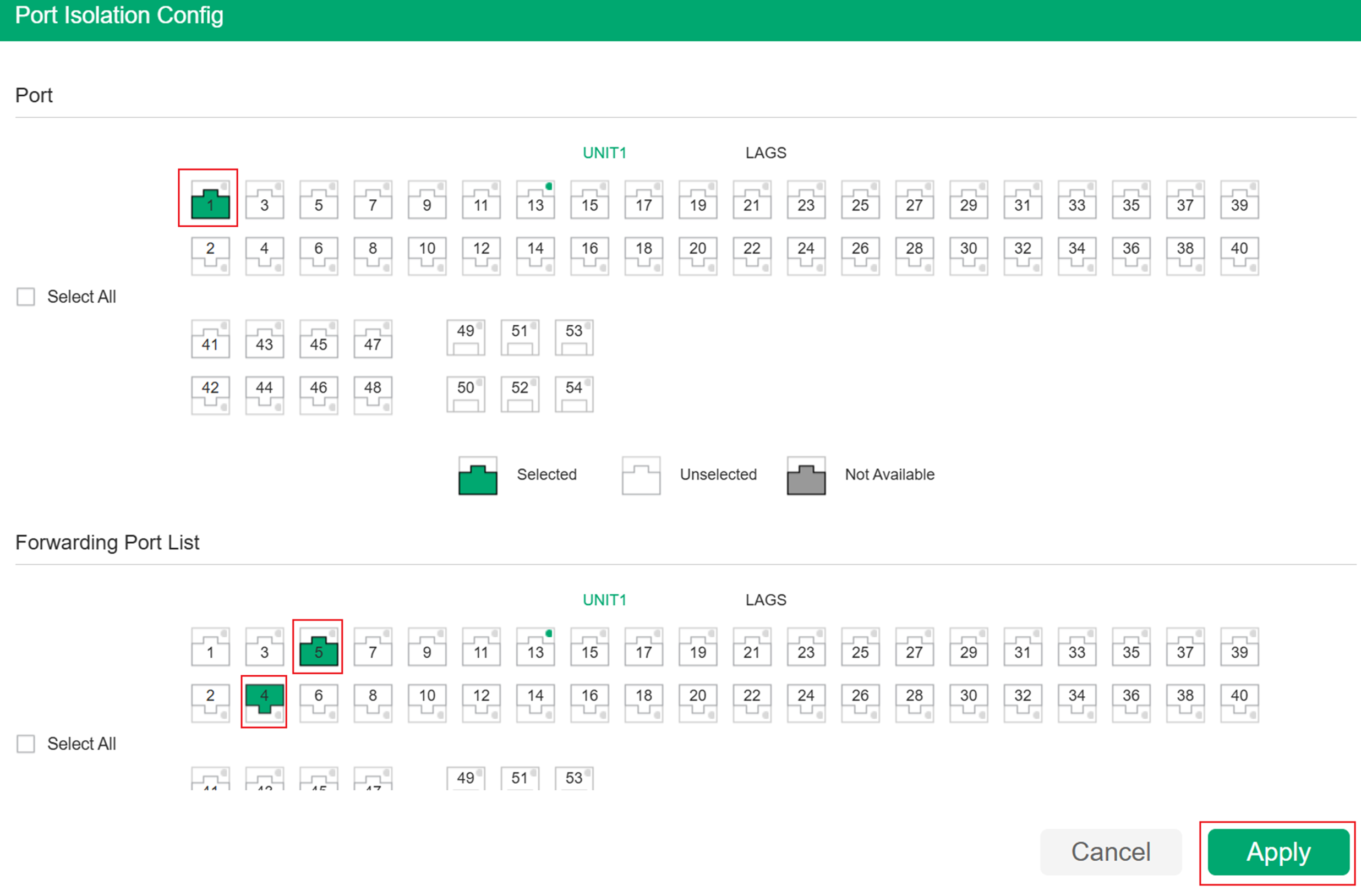
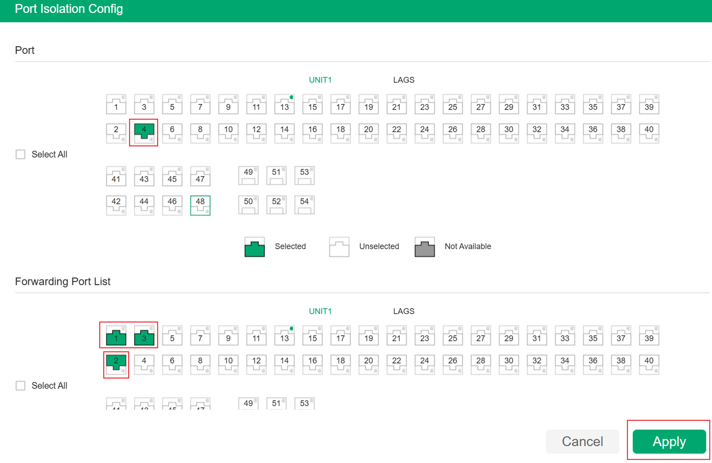
Step 1. Go to L2 Features > Switching > Port > Port Isolation page, click to load the following configuration page. Choose port 1 in the Port section, and choose port 4 and port 5 in the Forwarding Port List section. Then click Apply.
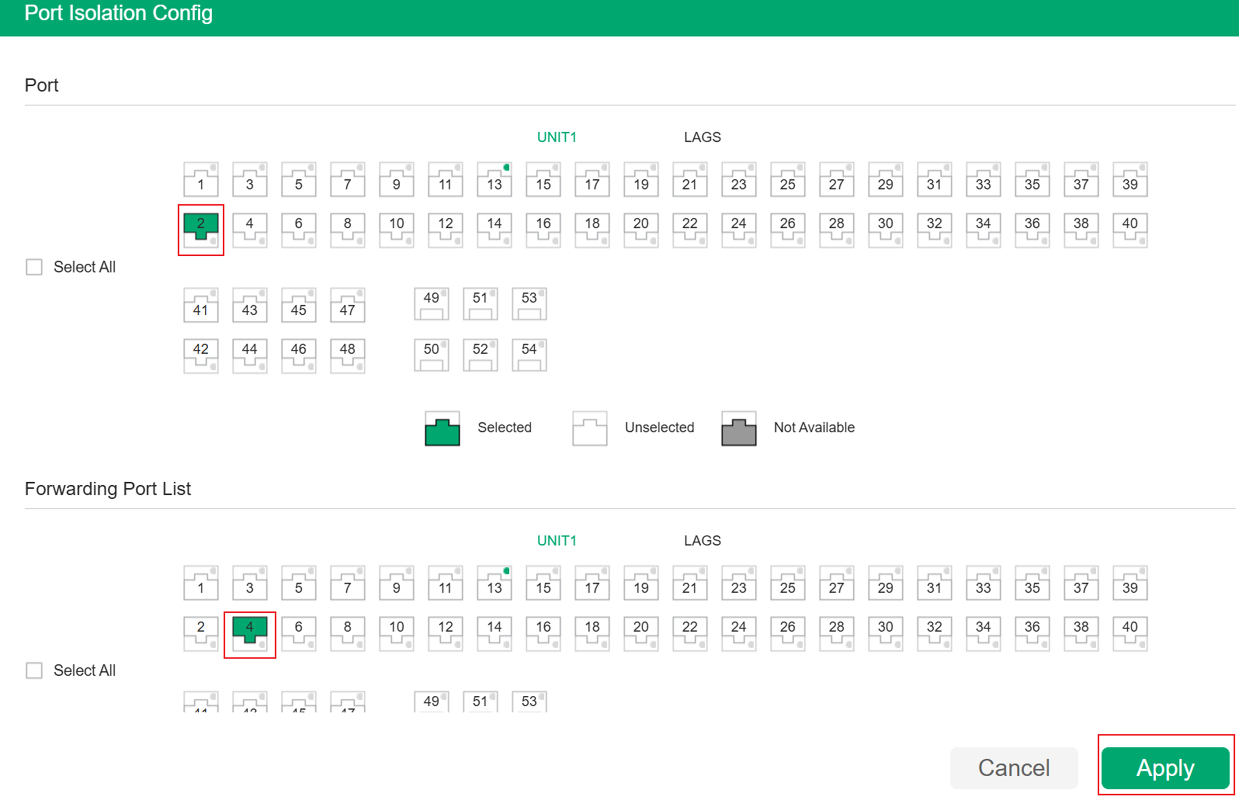
Step 2. Click to load the following configuration page. Choose port 2 in the Port section, and choose port 4 in the Forwarding Port List section. Then click Apply.
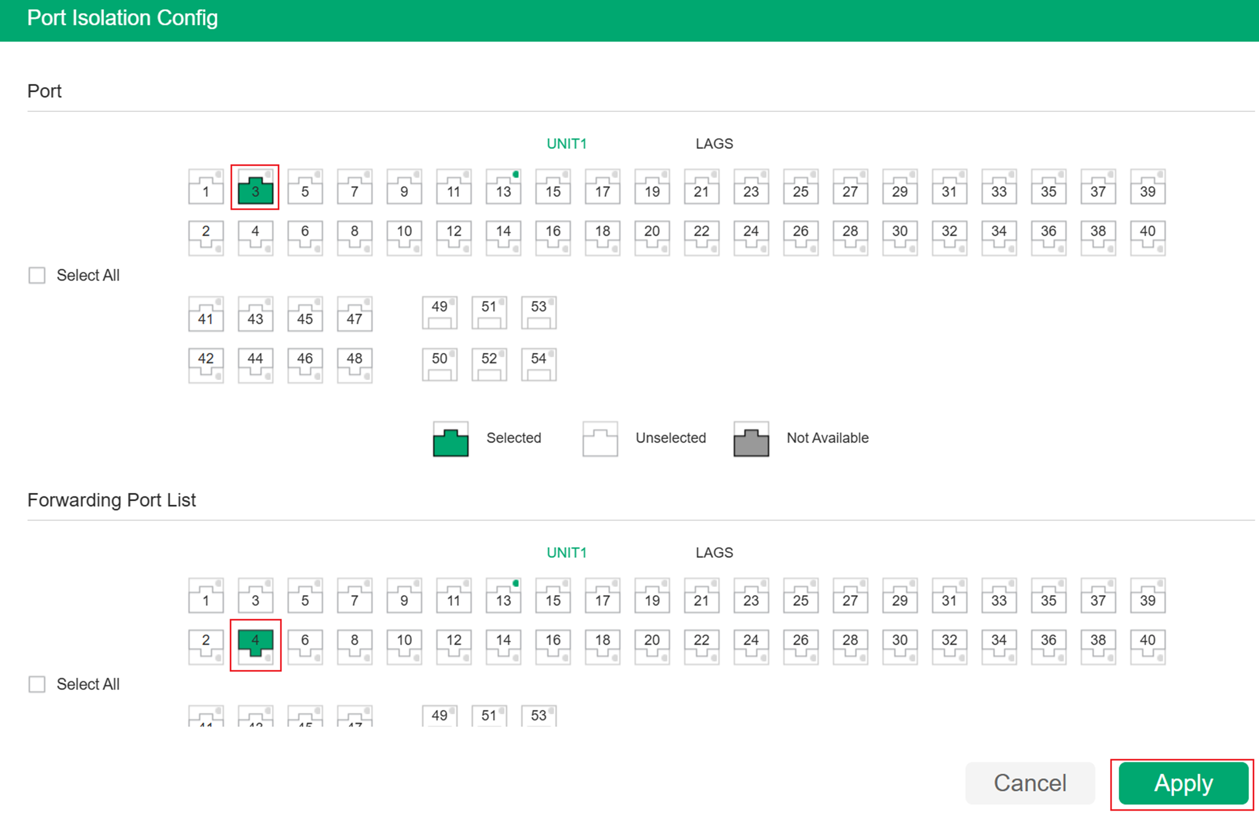
Step 3. Click to load the following configuration page. Choose port 3 in the Port section, and choose port 4 in the Forwarding Port List section. Then click Apply.
Step 4. Click to load the following configuration page. Choose port 4 in the Port section, and choose port 1, 2 and 3 in the Forwarding Port List section. Then click Apply.
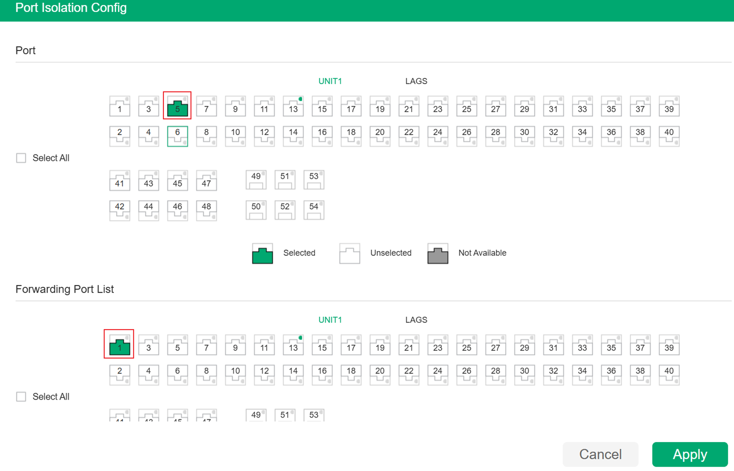
Step 5. Click to load the following configuration page. Choose port 5 in the Port section, and choose port 1 in the Forwarding Port List section. Then click Apply.
Configuration in Controller mode
In controller mode, when you set a port as isolated, it cannot communicate with other isolated ports.
In this example, Host A cannot communicate with Host B; however, both hosts can communicate with Host C, so you need to set ports 1 and 2 as isolated ports.
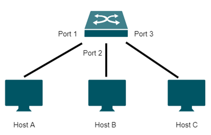
There are two ways to configure Port Isolation in controller mode. You can configure each switch port individually, or you can use a profile to apply the configuration in bulk more efficiently. In this scenario, you need to enable Port Isolation on both port 1 and port 2.
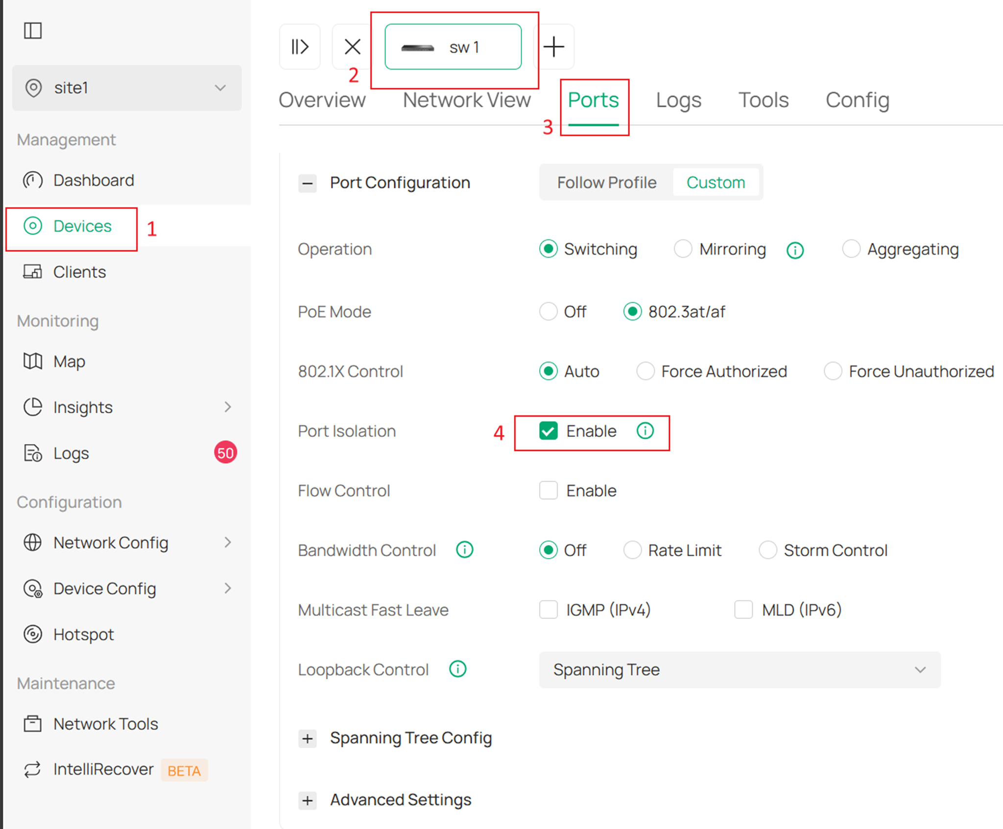
Method 1. Configure ports individually. Go to the Site page > Device > Port settings > Enable Port Isolation. Then click Apply.
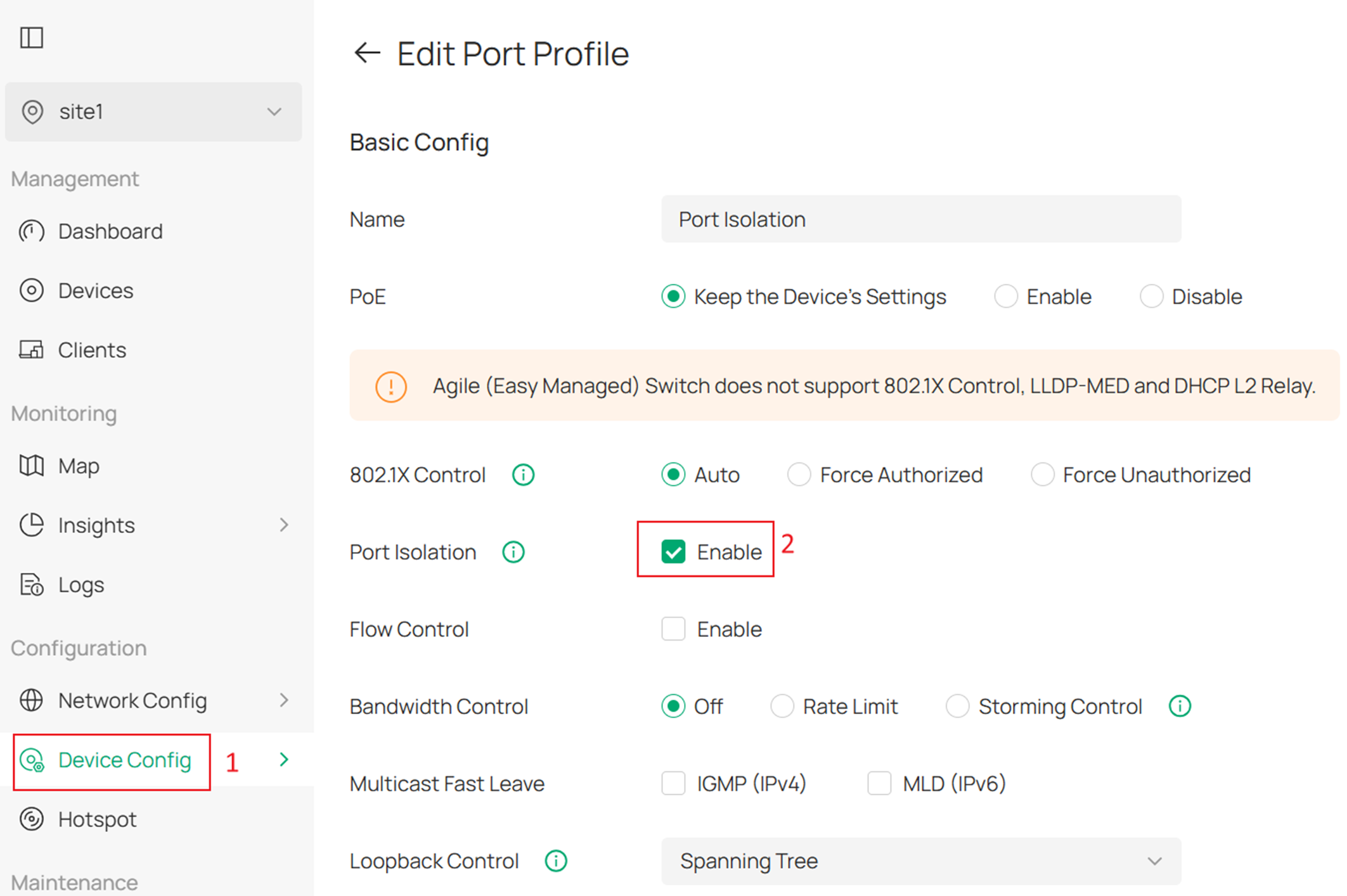
Method 2. Configure using a profile template. Go to Device Config > Switch Ports > Port Profile > Add Profile and create a new profile with Port Isolation enabled. Then click Apply.
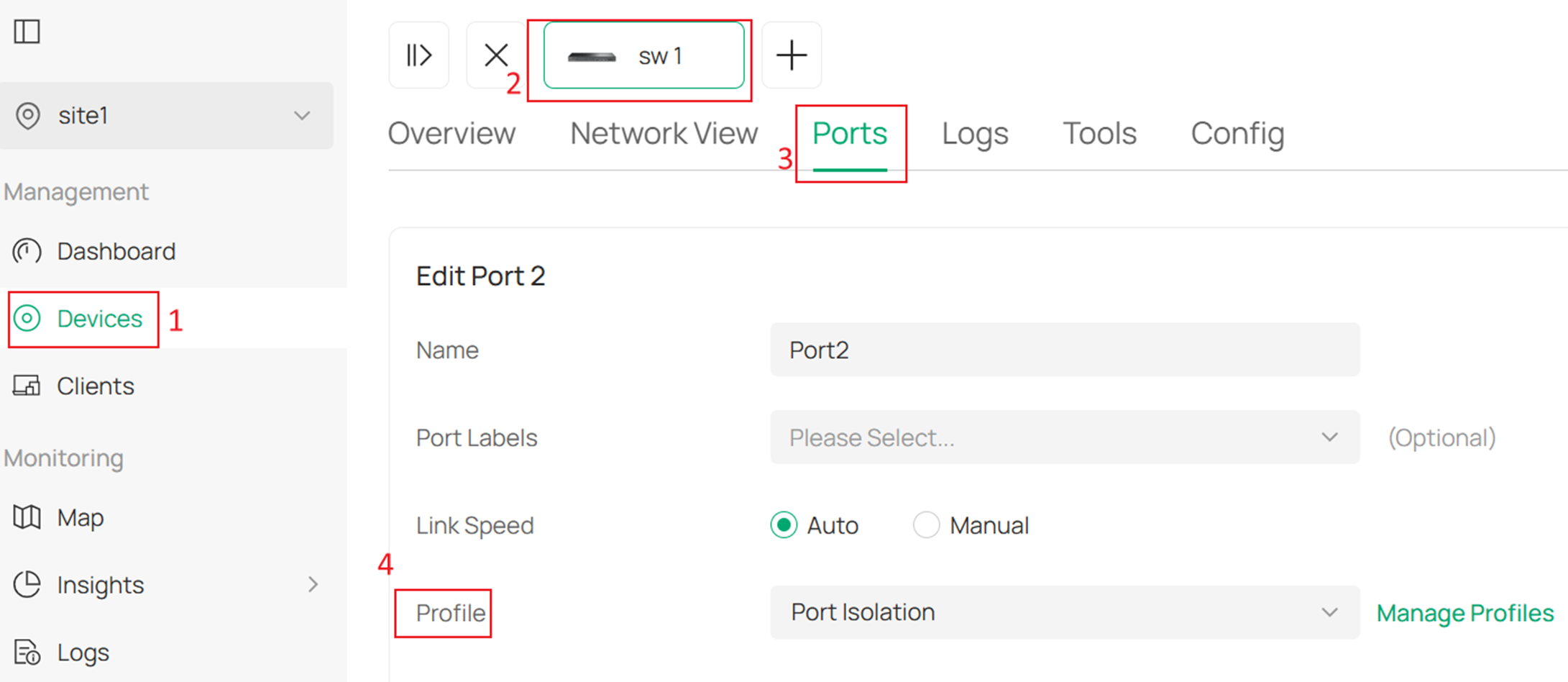
Then go to Devices > Ports > Profile, and apply this profile to the required ports. Then click Apply.
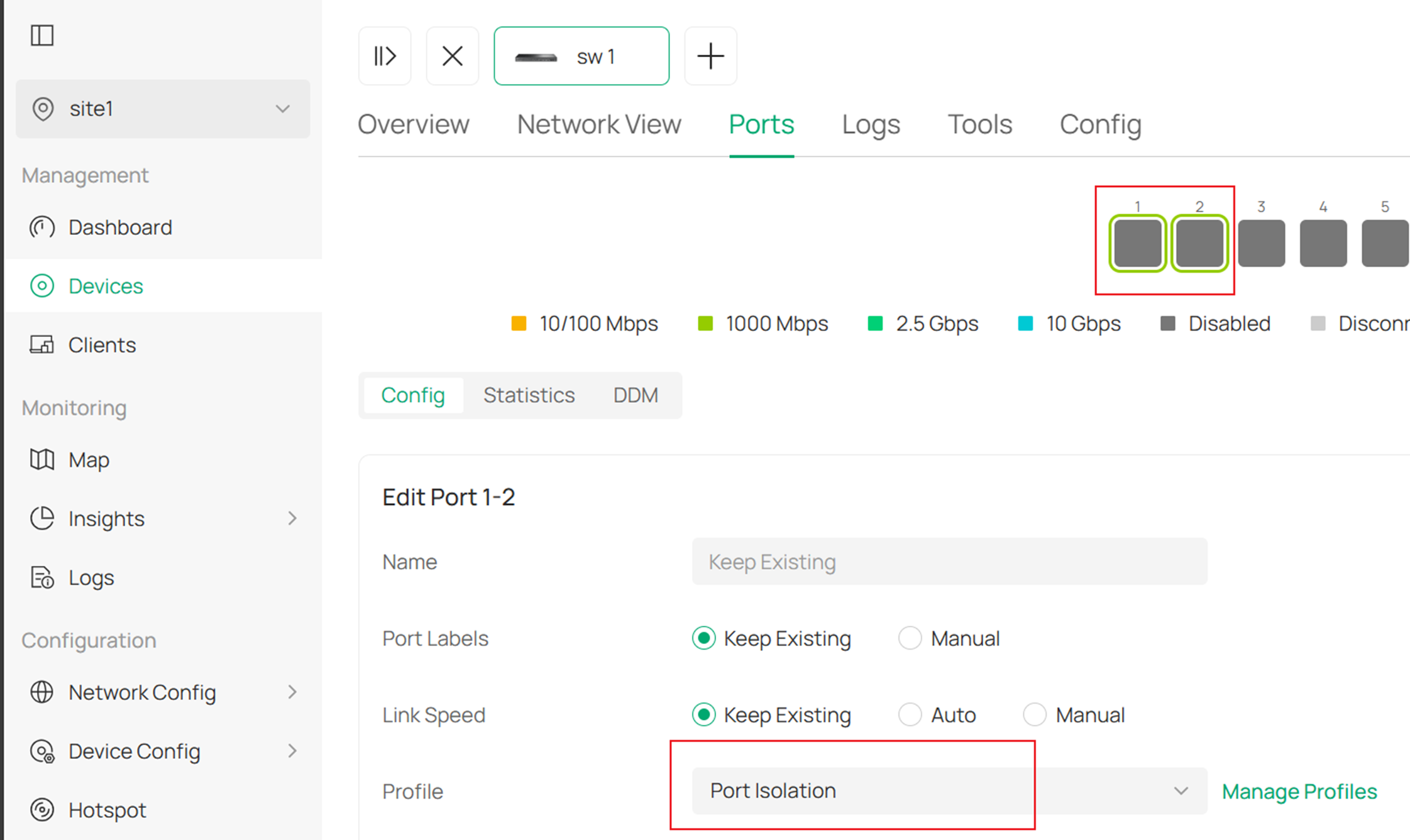
With this method, you can also select both port 1 and port 2 and apply the configuration at the same time.
Conclusion
This FAQ mainly explains the differences and configuration methods of Port Isolation in standalone mode and controller mode.
Get to know more details of each function and configuration please go to Download Center to download the manual of your product.
