


Contents
Introduction
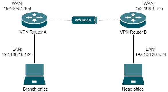
With the Site-to-Site VPN function, different private networks can be connected over the internet. Take the following topology as an example to learn how to configure the Site-to-Site IPsec VPN in Standalone Mode.
Requirements
- Omada Gateway
- PC
Configuration
Step1. Verify the settings needed for IPsec VPN on the router.
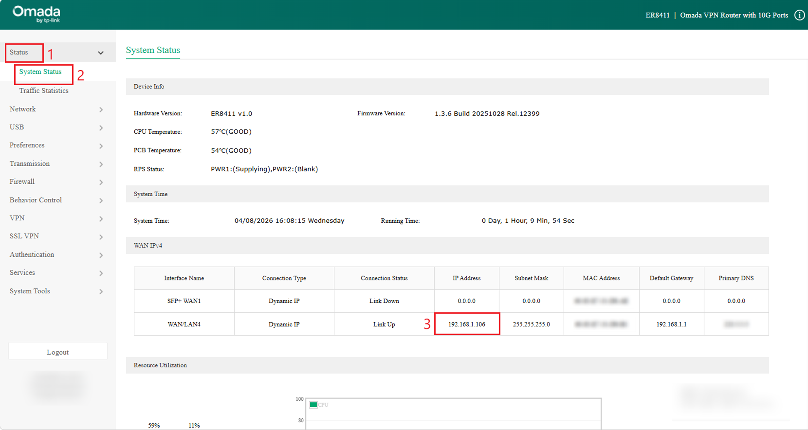
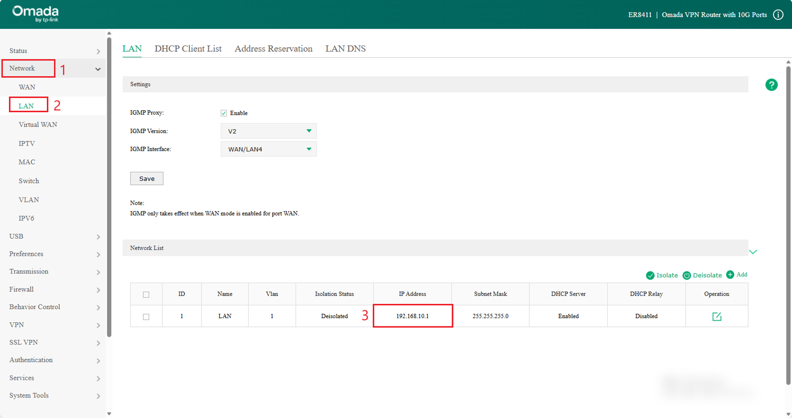
- Check the WAN IP and LAN IP of VPN Router A.
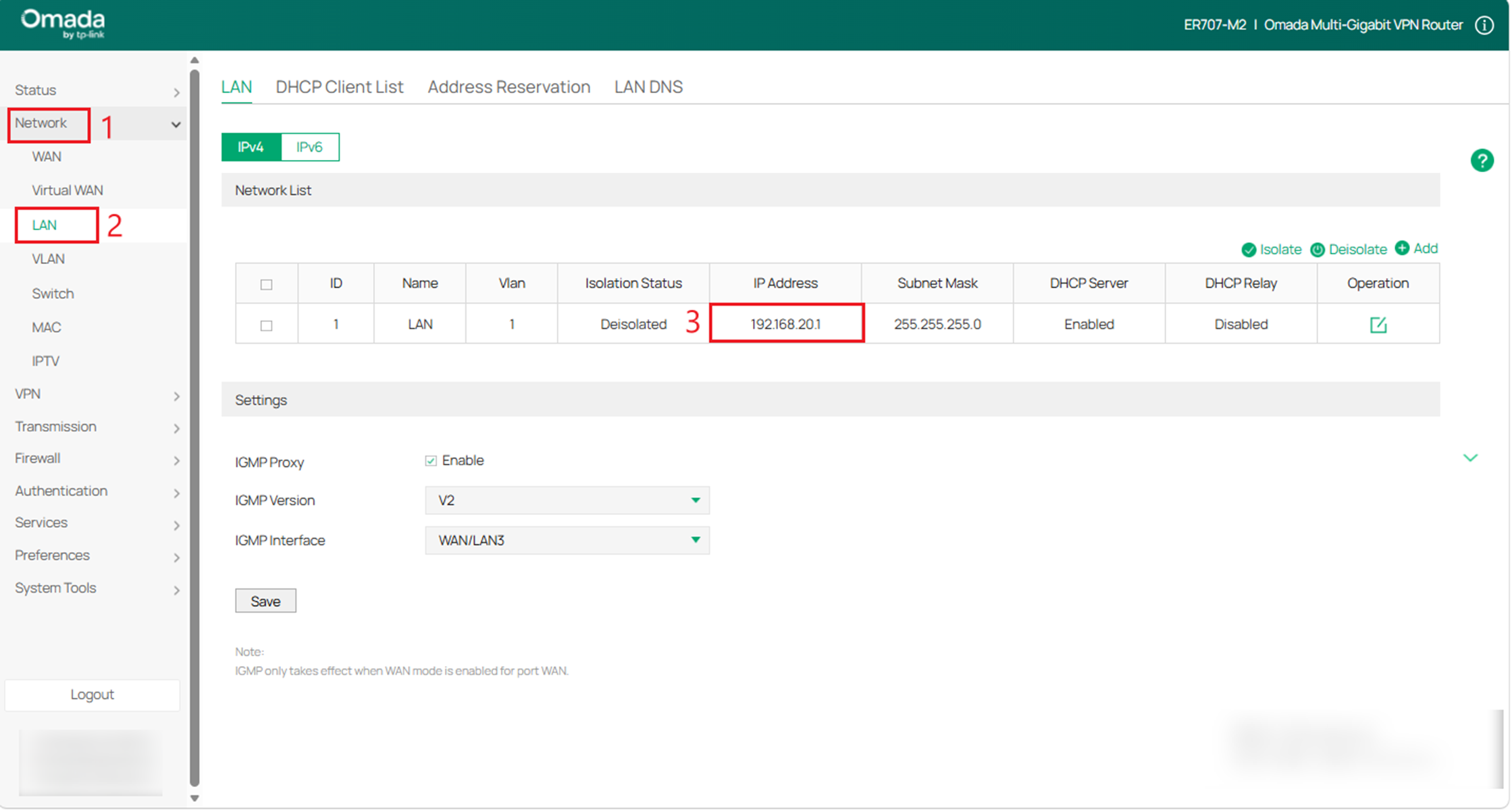
Choose the menu Status > System Status and Network > LAN.
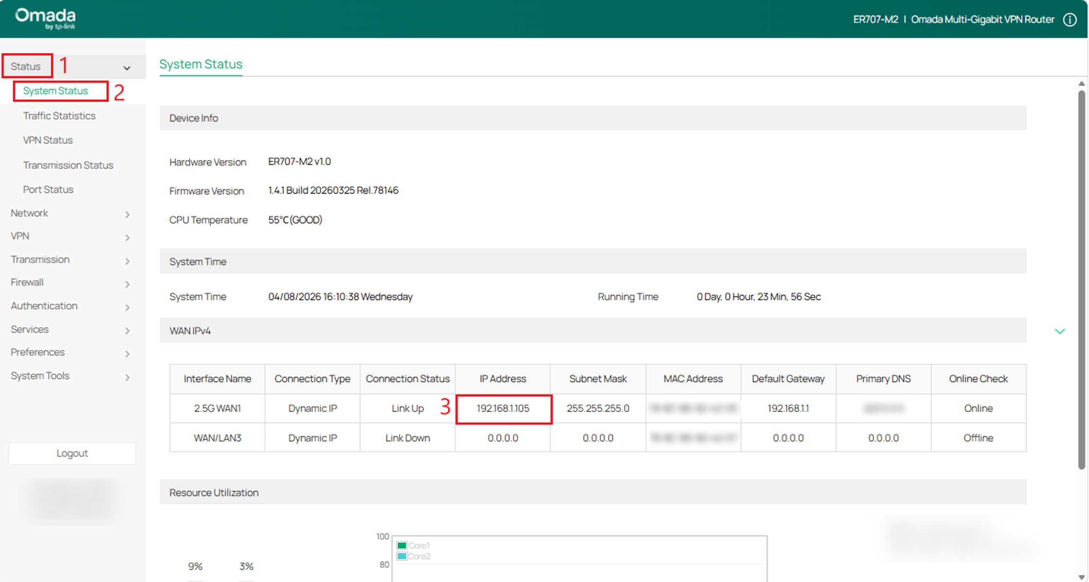
- Check the WAN IP and LAN IP of VPN Router B.
Choose the menu Status > System Status and Network > LAN.
Step 2. Configure IPsec VPN settings on Router A
(1) Choose the menu VPN > IPSec > IPSec Policy > IPsec Policy List and click Add to load the following page on the VPN router. Configure the basic parameters for the IPsec policy.
·Specify the Mode as LAN-to-LAN.
·Specify the Remote Gateway.
·Specify the WAN.
·Specify the Local Network as LAN and the Remote Subnet.
·Specify the Pre-shared Key as you like.

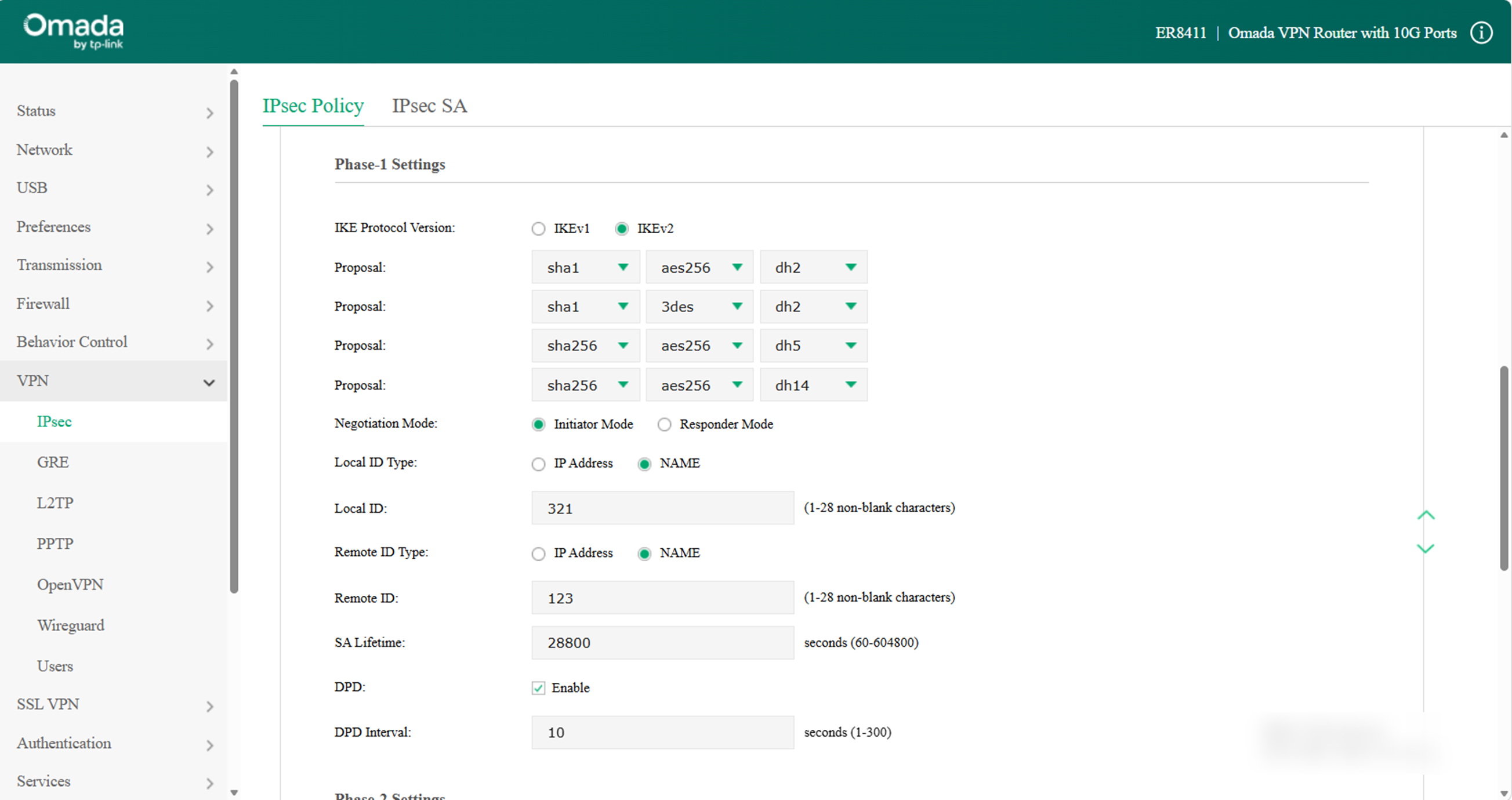
(2) Click Advanced Settings to load the following page. In the Phase-1 Settings section, configure the IKE phase-1 parameters.
Note: Phase settings on both sides must match.
·Select sha1-aes256-dh2 as the proposal or keep the default settings.
·Specify Negotiation Mode.
Initiator Mode: The local device initiates a connection to the peer.
Responder Mode: The local device responds to a connection from the peer.
·Specify Local/Remote ID Type.
When one router is behind a NAT, you can use IP Address instead of NAME as the Local/Remote ID Type in the following scenarios:
If router (A) is behind a NAT, enter the public IP address of the other router (B) in the Remote Gateway field.
If the other router (B) is on the public network, enter 0.0.0.0 in the Remote Gateway field.
Otherwise, select NAME as the Local/Remote ID Type.
·Specify the Local/Remote ID as you like. Here we specify the Local ID as 321 and the Remote ID as 123.
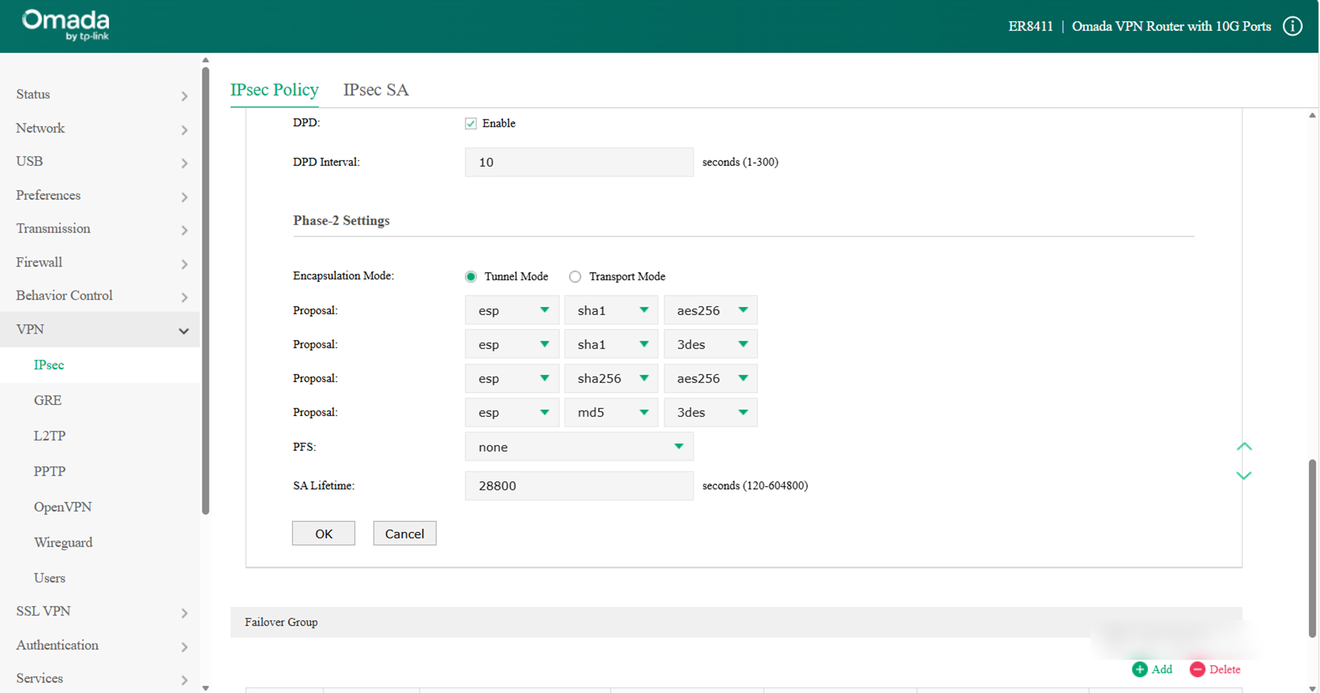
(3) In the Phase-2 Settings section, configure the IKE phase-2 parameters. Click OK.
Encapsulation Mode: Specify the Encapsulation Mode as Tunnel Mode or Transport Mode. When both ends of the tunnel are hosts, either mode can be chosen. When at least one of the endpoints of a tunnel is a security gateway, tunnel mode is recommended to ensure safety.
Select esp-sha1-aes256 as the proposal or keep the default settings.
Once the router is behind a NAT device, the proposal cannot be specified as ah-md5/sha1/sha256/sha384/sha512; otherwise, the VPN tunnel can’t be established.
Step 3. Configure IPsec VPN settings on Router B
Due to a system upgrade, there are some differences in the web UI. However, the configuration process remains similar.
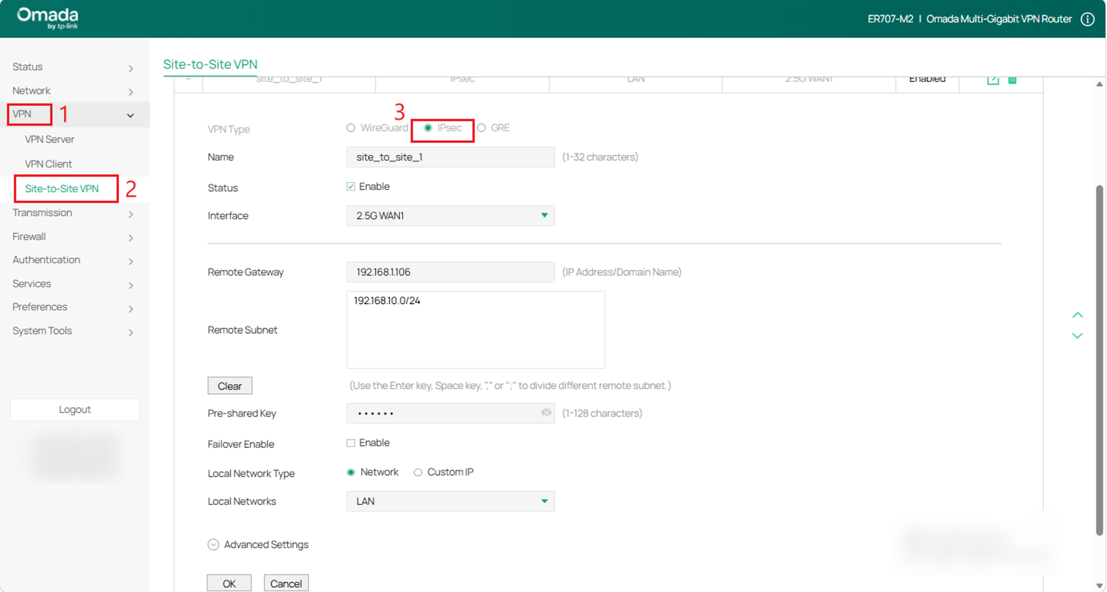
(1) Choose the menu VPN > Site-to-Site VPN and click Add to load the following page on the VPN router B. Select IPsec as VPN Type and configure the basic parameters.
(2) Click Advanced Settings to load the following page. In the Phase-1 Settings section, configure the IKE phase-1 parameters.
Initiator Mode: The local device initiates a connection to the peer.
Responder Mode: The local device responds to a connection from the peer.
Note: If the remote gateway for either site is configured as 0.0.0.0, the Negotiation mode must be set to Responder mode.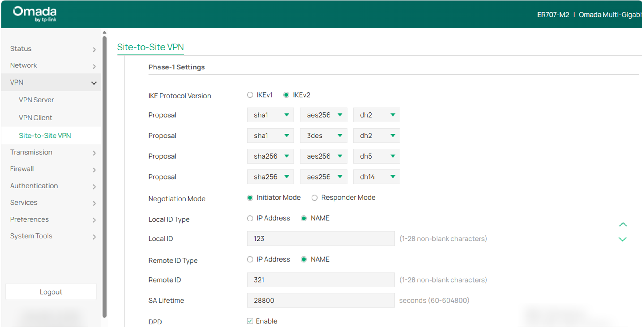
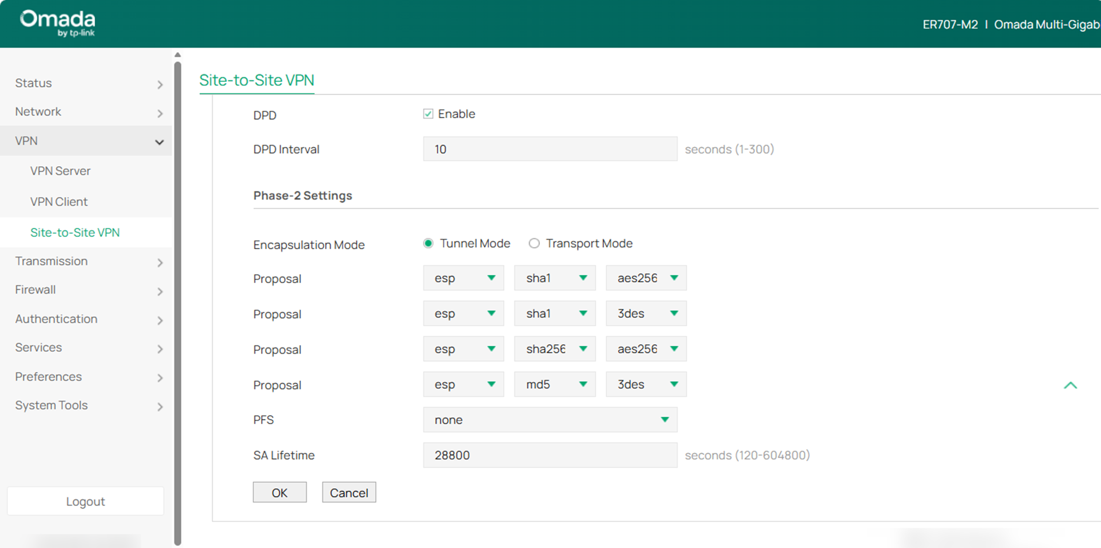
(3) In the Phase-2 Settings section, configure the IKE phase-2 parameters. Click OK.
Verification
Check the connection status of the IPsec VPN tunnel.
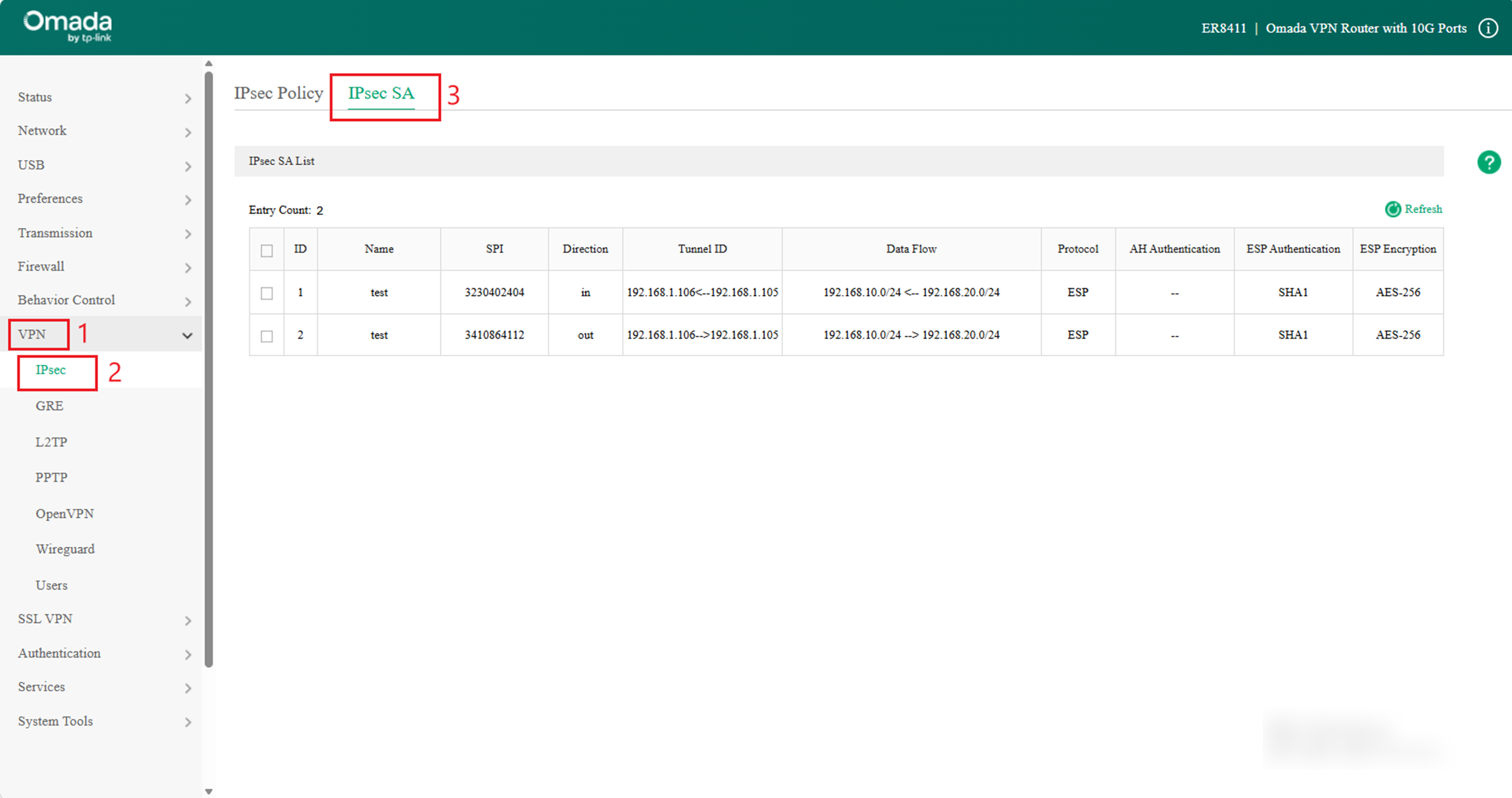
For router A, navigate to VPN > IPsec > IPsec SA to load the following page. If the IPsec VPN tunnel is established successfully, it will be displayed in the list.
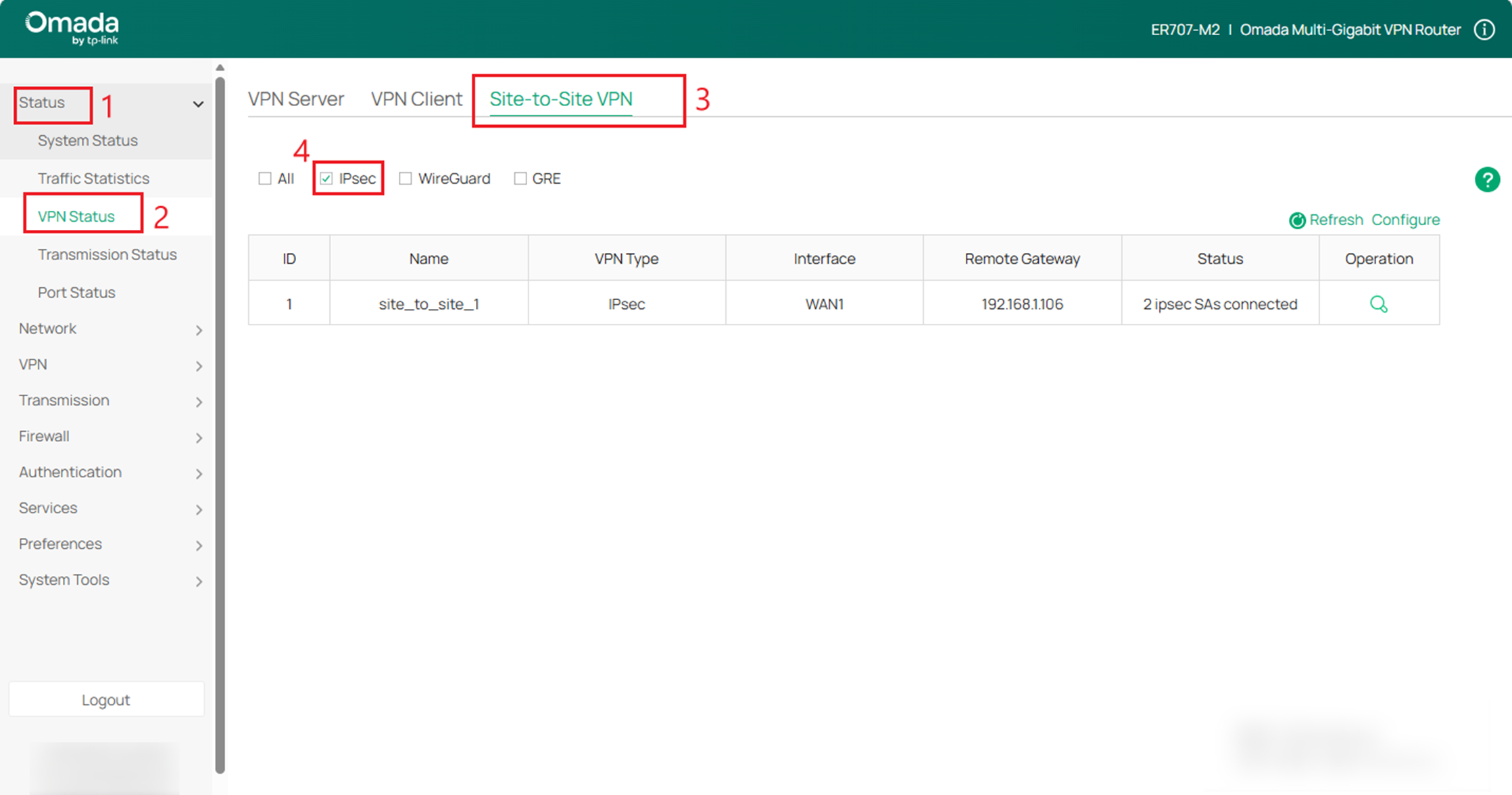
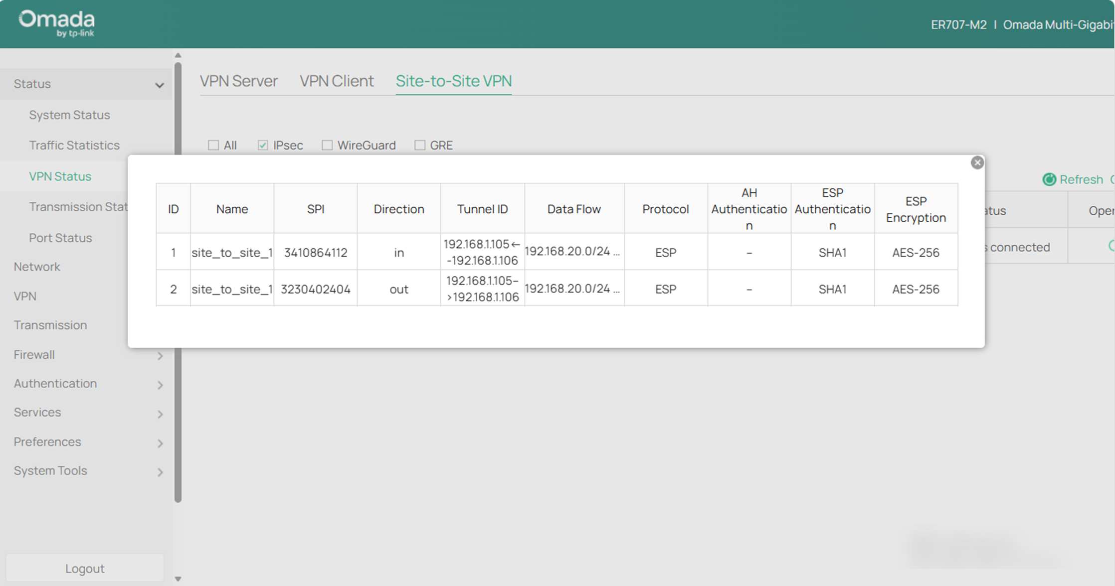
For router B, navigate to Status > VPN Status > Site-to-Site VPN > IPsec to load the following page. Click the button under Operation on the right to view details.
Conclusion
Now you have learned how to configure IPsec Site-to-Site VPN in standalone mode.
To learn more about each function and configuration, please visit Support Home to download or check the manual for your product.
