


Content
Introduction
Dual PoE input is a power and network connectivity design that allows an access point to receive power through two PoE-capable Ethernet ports. This feature is intended for deployments that require greater power-source flexibility, improved service continuity, or redundant power and data paths.
It is particularly useful in business-critical wireless environments where an interruption to a single PoE source, Ethernet cable, or upstream switch port could affect network availability. It can also provide an alternative deployment option when a single high-power PoE source is unavailable. Depending on the power sources, connection method, and network configuration, the access point may operate with full functionality, provide redundancy, or enter a limited-performance mode when the available power is insufficient.
This FAQ introduces the concept of dual PoE input, deployment considerations, and expected device behavior under different power-supply conditions.
Requirements
- Omada Controller v6.3 or above.
- The following model of Omada AP:
|
Model |
Hardware Version |
Firmware Version |
|
AP9788 |
1.0 |
1.0.0 or above |
Configuration
This section describes how to deploy dual PoE power and view the relevant information in both Controller and Standalone modes.
In Controller Mode
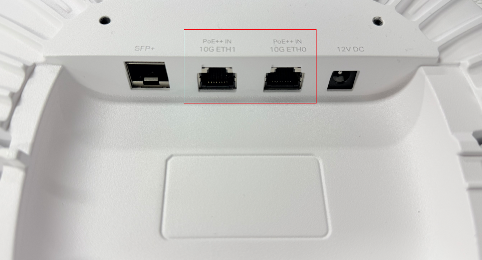
Step 1. Connect the RJ45 Ethernet cable from the PoE output port of the PoE power-sourcing equipment (PSE) to the AP's ETH0 port, ETH1 port, or both ports to power the AP.
Step 2. Discover and adopt the AP in the Controller.
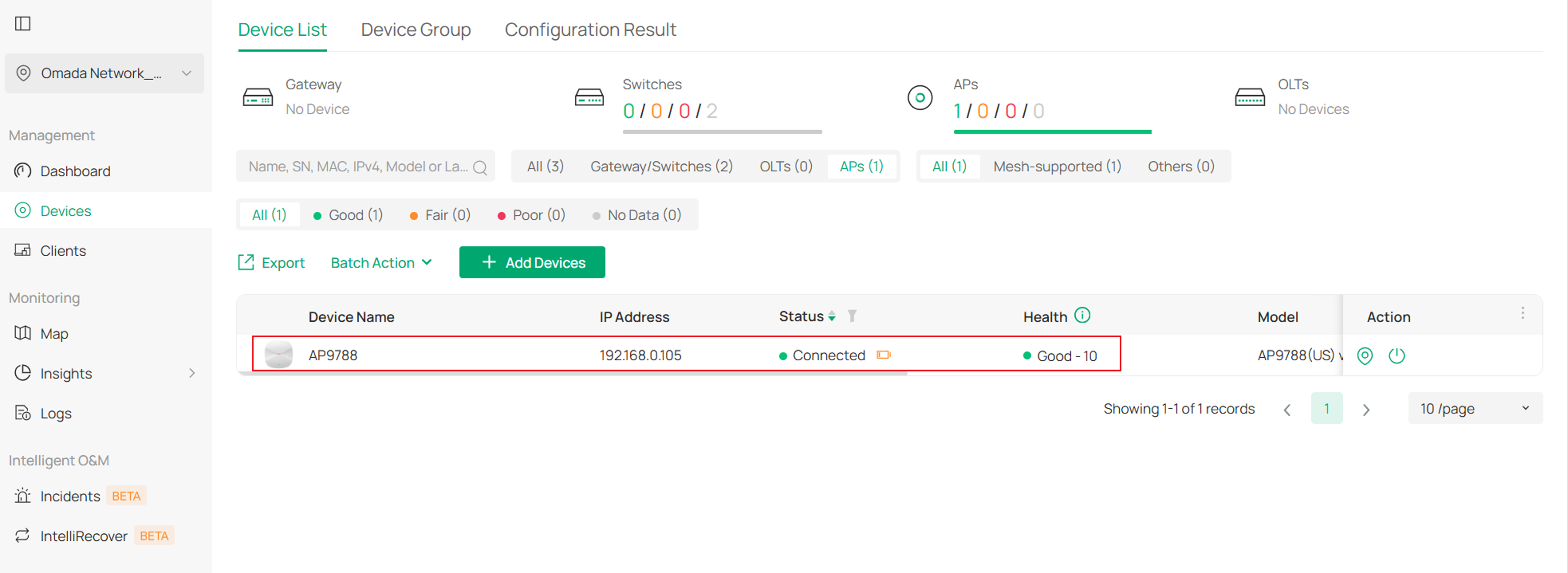
Step3. Check the AP’s PoE power status and verify that both PoE connections are functioning properly.
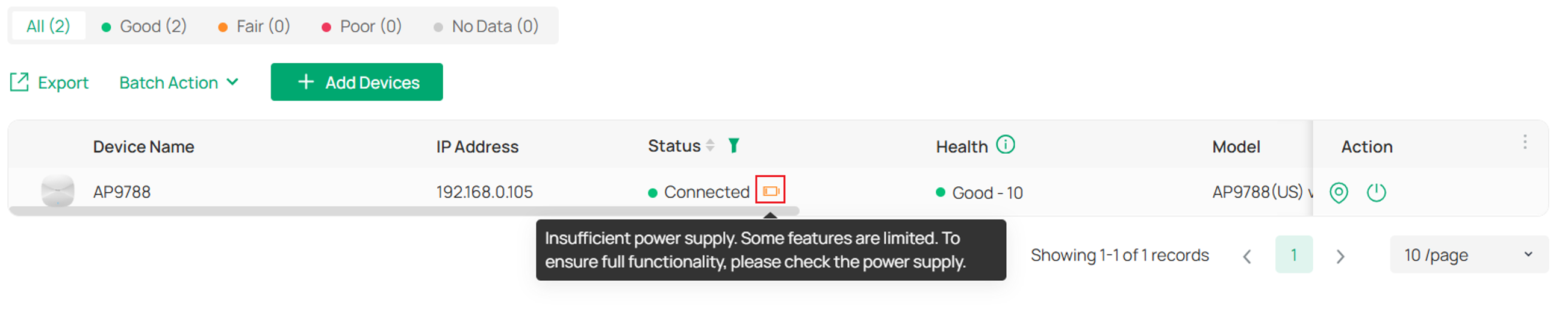
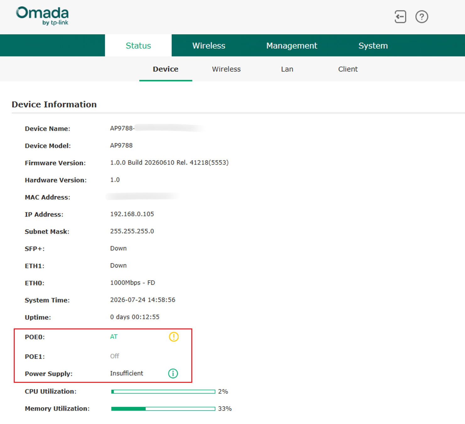
If the device is receiving insufficient power, a warning icon will appear in the Status column. Hover over the icon to view the relevant message: “Insufficient power supply. Some features are limited. To ensure full functionality, please check the power supply.” You can then determine whether the AP is receiving sufficient power.
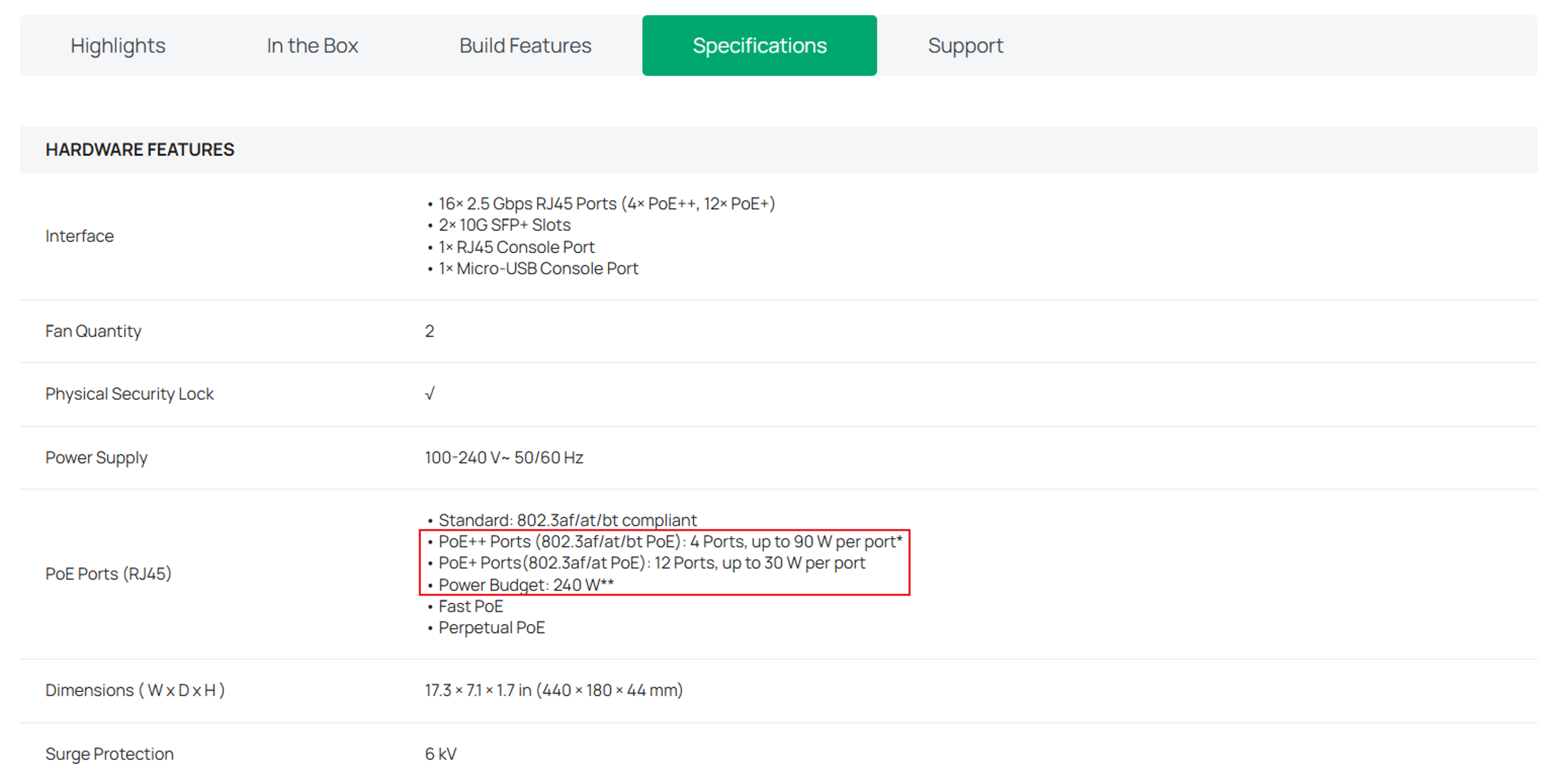
Note: If you need to verify the power supply specifications of an Omada switch, open the switch’s product page on the Omada website and check the PoE Ports parameter in the Specifications section.
Navigate to Manage Device > Ports. In the PoE In column, you can view the PoE standard negotiated on each of the two ports.
PoE standards define the amount of power that can be delivered to a powered device (PD) over an Ethernet cable. Common standards include IEEE 802.3af, IEEE 802.3at, and IEEE 802.3bt. Higher PoE standards generally support higher power output. The actual negotiated standard depends on the capabilities of both the AP and the PoE power sourcing equipment (PSE).
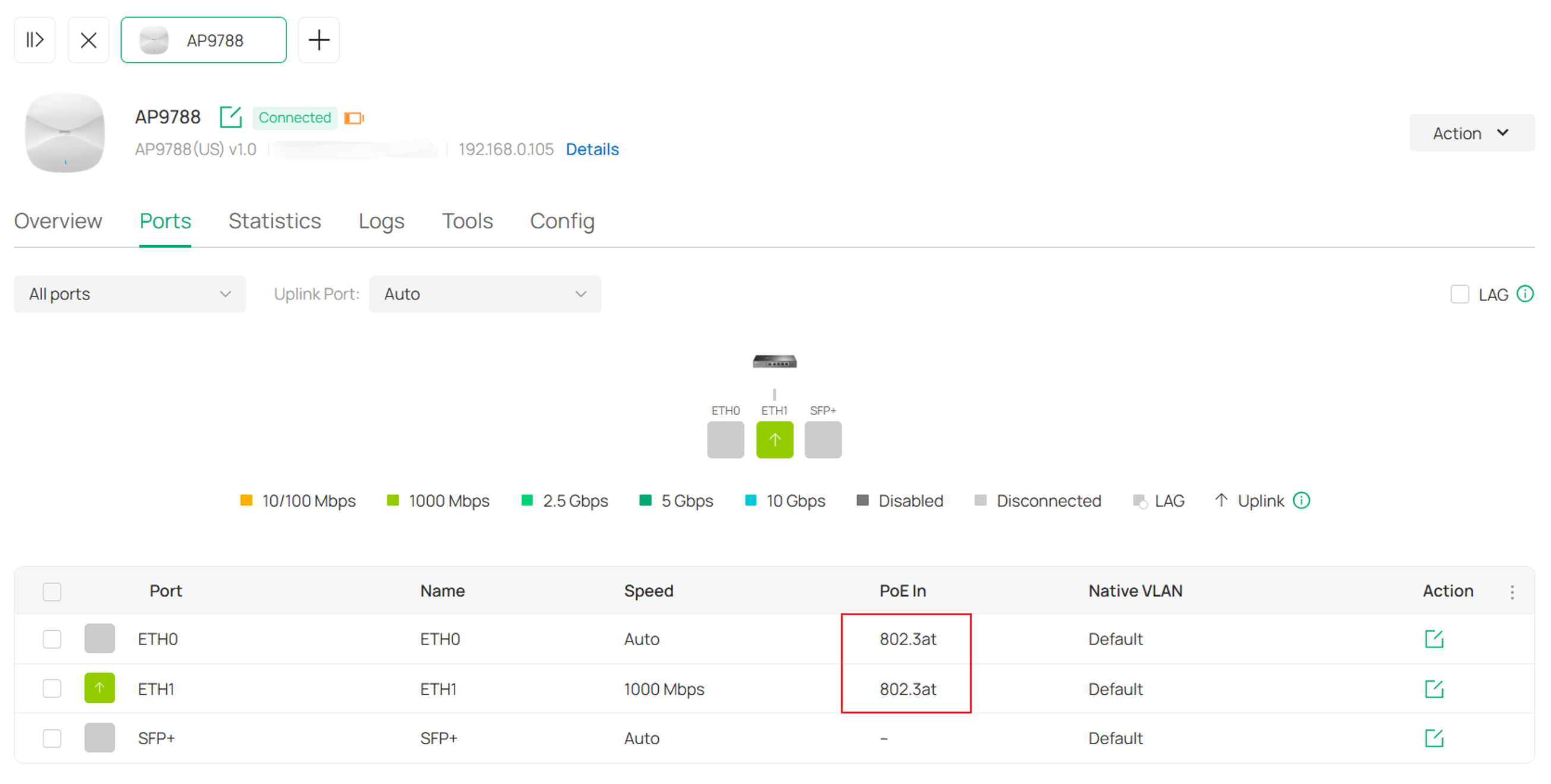
Note: If the two PoE-IN ports receive power from different switches, the AP will be displayed under the device corresponding to the port currently serving as the Uplink in the topology view.
In Standalone Mode
Step 1. Access the Standalone web interface using the device’s IP address and complete the Quick Setup process. Then navigate to the Status> Device page.
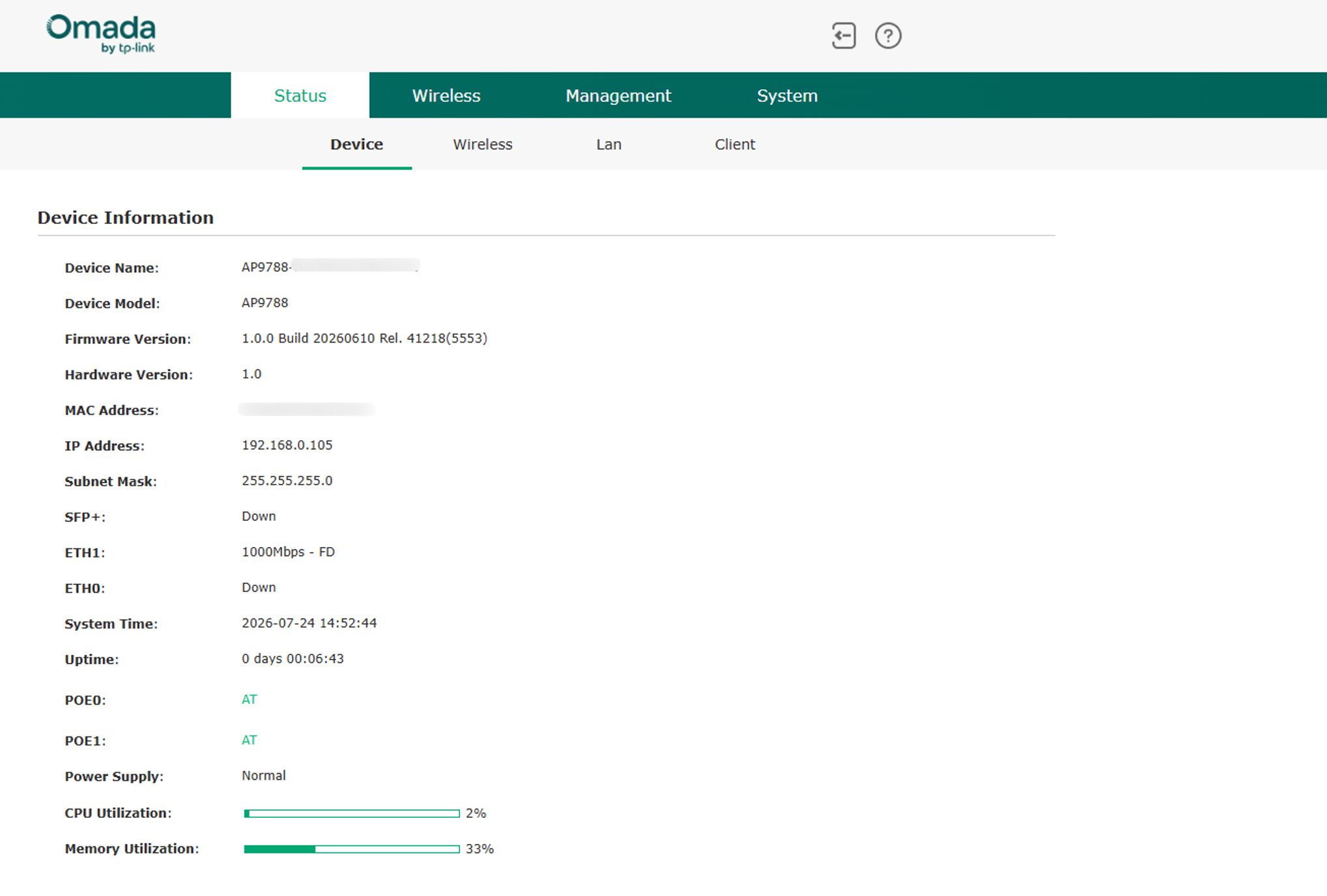
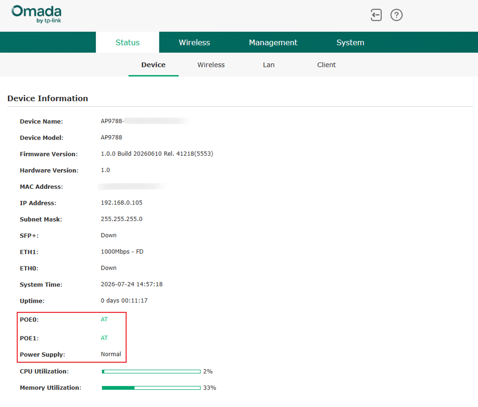
Step 2. In Status > Device, you can view the power source information for each port, including the negotiated PoE standard, as well as the overall power supply status of the device.
The following image shows a device with sufficient power supply:
The following image shows a device with insufficient power supply:
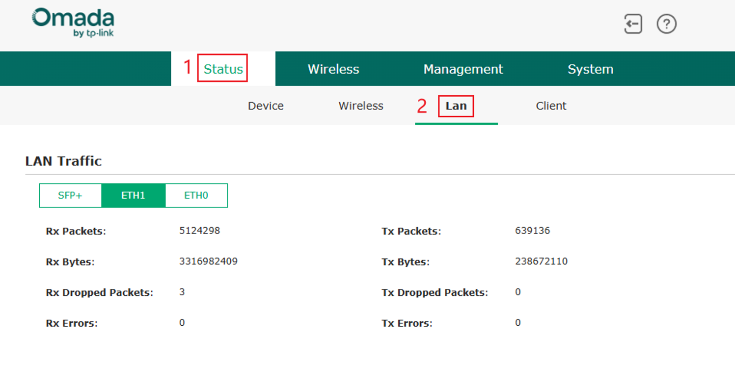
In Status > LAN, you can also view the traffic statistics for each Ethernet port.
Conclusion
You have now successfully configured Dual PoE Powering on the Omada Campus AP and verified the power status of both PoE input ports. By using Dual PoE Powering, you can provide greater power-source flexibility, improve service continuity through power redundancy, and ensure stable AP operation in demanding network environments. When deployed with LAG, Dual PoE connections can also help enhance link reliability and network availability.
To learn more about each function and configuration, please visit Support Home to download or check the manual for your product.
QA
Q1: What is Dual PoE Powering, and what are its advantages over Single PoE Powering?
A1: Dual PoE Input allows an AP to receive power from two PoE sources simultaneously. Compared with single PoE powering, it provides the following benefits:
- Two IEEE 802.3at (PoE+) power sources can provide power equivalent to a single IEEE 802.3bt source, offering greater deployment flexibility when a PoE++ switch is unavailable.
- Dual power and data paths provide redundancy. If one PoE source, Ethernet cable, or switch port fails, the other link can continue supplying power and data connectivity, improving service continuity and reducing downtime.
Q2: Which power supply method provides the best AP performance?
A2: The APs support Dual PoE Input for power and data redundancy. When sufficient power is available, Dual 802.3at, Single 802.3bt, and DC power provide the same level of device performance. There is no performance advantage to using one of these power methods over another, if the AP receives adequate power.
Q3: Will connecting both Ethernet ports to the same switch create a network loop?
A3: Yes. Connecting both Ethernet ports directly to the same switch without link aggregation may create a network loop. To prevent this, configure LAG (Link Aggregation Group) on both the switch and the AP before connecting both Ethernet ports to the same switch.
Q4: What functionality is affected when the AP receives insufficient power?
A4: When the AP receives insufficient power, the USB and SFP functions will be disabled. Additional limitations depend on the negotiated PoE power level:
- Single 802.3at Power:
The AP operates in 2×2 MIMO mode instead of 4×4 MIMO mode.
Wireless performance is reduced.
Only the powered Ethernet port can carry network traffic.
- Single 802.3af Power:
Wireless functionality is disabled.
Only the powered PoE port supports LAN communication.
Maximum Ethernet speed is limited to 1 Gbps.
- 802.3af + 802.3at Power:
The AP remains in 4×4 MIMO mode.
Maximum transmit power is reduced by approximately 3 dB, which may affect wireless coverage and performance.
- 802.3af + 802.3af Power:
The AP switches from 4×4 MIMO to 2×2 MIMO mode.
Wireless performance is reduced.
Only ETH1 supports network communication.
Q5: Do the two PoE power sources need to come from the same switch?
A5: No. The two PoE connections can originate from either the same switch or two different PoE switches.
- If both connections originate from different switches, Dual PoE can provide both power redundancy and network redundancy, provided the network topology is configured correctly.
- If both connections originate from the same switch, configure LAG before connecting both Ethernet ports to avoid creating a network loop.
If the AP is to be powered through two PoE connections from the same switch, configure a LAG on both the AP and the Switch before connecting the two PoE cables. Please follow the steps below.
What is LAG?
LAG (Link Aggregation Group) combines multiple Ethernet links into a single logical connection to increase bandwidth and enhance network reliability. It also provides link redundancy, allowing network traffic to continue through the remaining active links if one link fails.
Benefits of LAG:
1. Prevent Network Loops
When multiple ports on a device are connected to the same switch, enabling LAG groups the links into a single logical connection. This helps prevent network loops, which can otherwise cause broadcast storms, network congestion, and degraded performance.
2. Increase Bandwidth
LAG combines multiple physical links into one logical link, increasing the available bandwidth between devices. This is especially useful when a single network link cannot meet throughput requirements.
3. Enable Load Balancing
LAG distributes traffic across member links using a hashing algorithm. This helps balance network traffic and improve overall link utilization.
4. Improve Reliability and Redundancy
LAG continuously monitors the status of member links. If one link fails, traffic is automatically redirected through the remaining active links, minimizing service disruption and improving network availability.
In Controller Mode:
If you plan to connect both PoE ports of the AP to the same switch, enable LAG for the AP under Manage Device > Ports before making the connections. Otherwise, a network loop may occur, preventing the AP or the network from functioning properly.
For Omada Switches, go to Manage Device > Ports, select the two ports connected to the AP, set Operation to Aggregation, assign both ports to the same LAG ID, select the appropriate LAG mode, confirm both member ports, and click Apply.
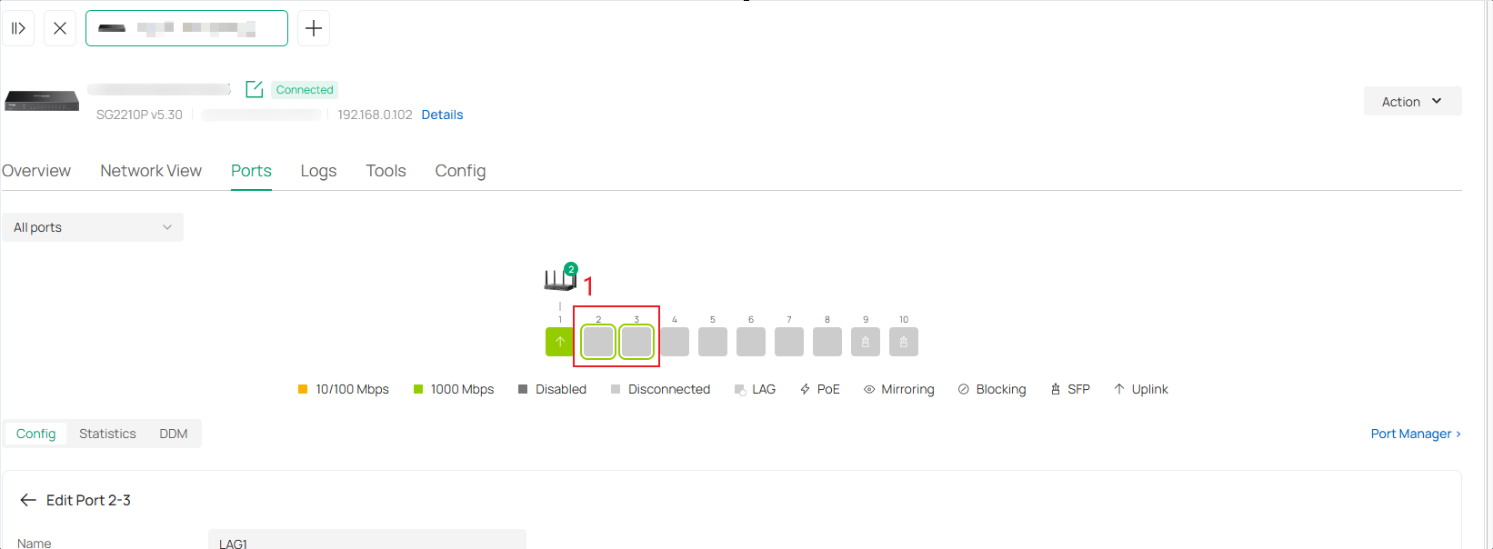
For more details, please refer to the following FAQ: How to configure LAG (LACP) on Omada Switches via Omada Controller.
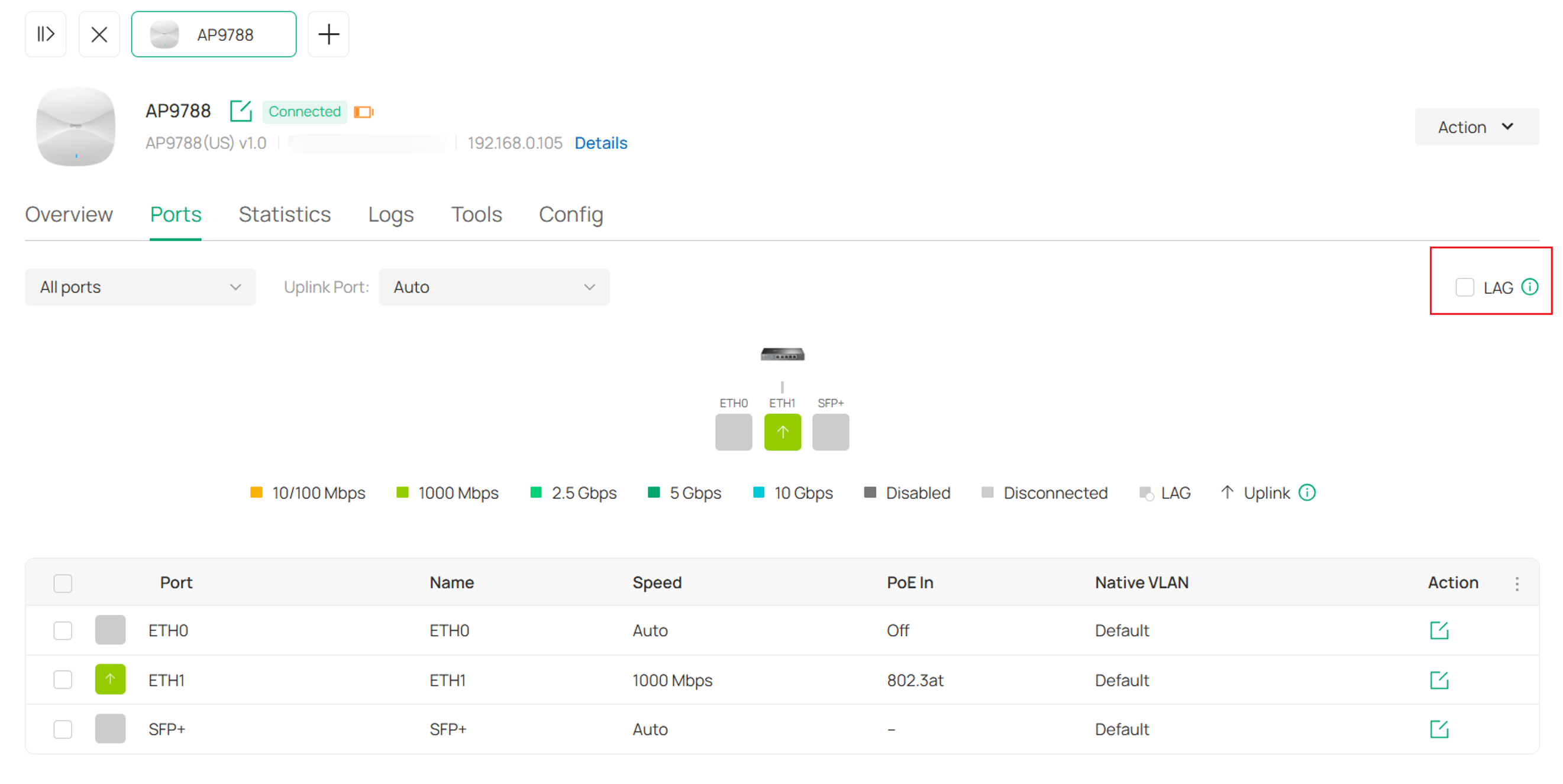
For Omada APs, go to Manage Device > Ports, enable LAG feature.
Select the LAG mode for traffic distribution. The default mode is recommended for most deployments.
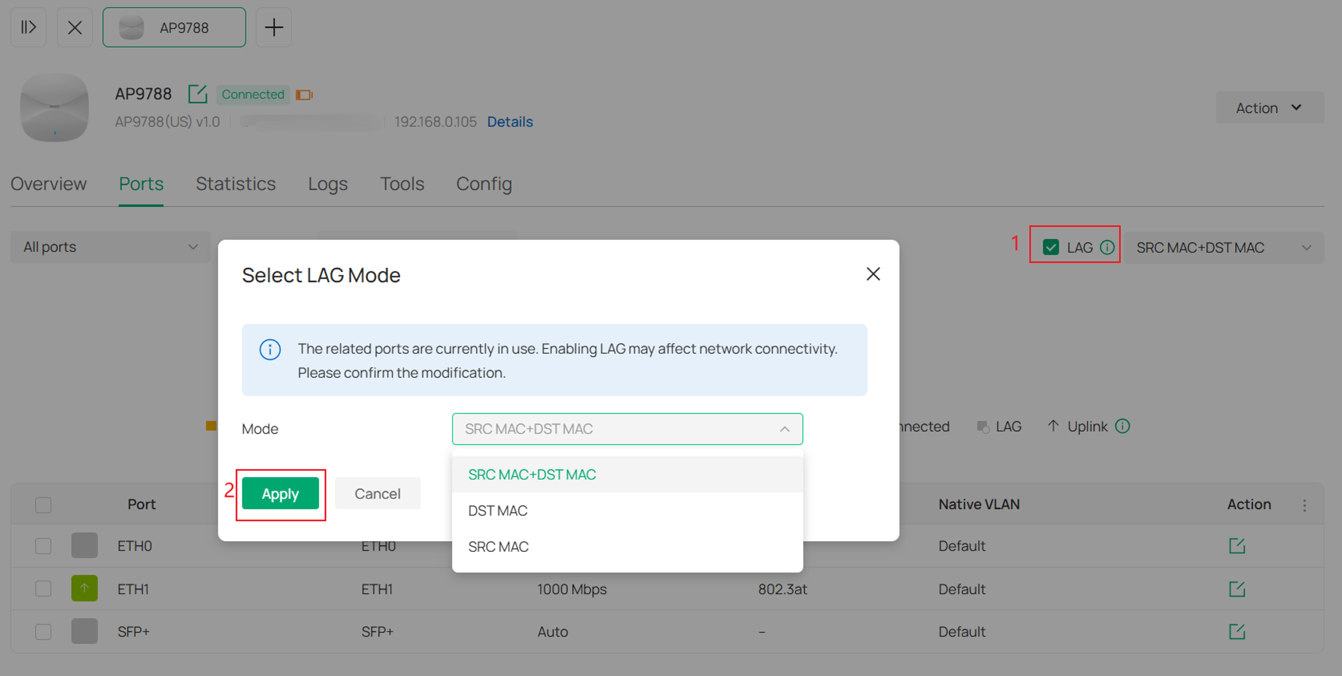
LAG Modes:
- SRC MAC + DST MAC
Traffic is distributed based on both the source and destination MAC addresses, providing the most balanced load distribution across LAG member ports.
- DST MAC
Traffic is distributed based on the destination MAC address. Frames destined for the same device are forwarded through the same LAG member port.
- SRC MAC
Traffic is distributed based on the source MAC address. Frames originating from the same device are forwarded through the same LAG member port.
Note: These modes only determine how traffic is distributed across LAG member links. They do not affect the total available bandwidth or the redundancy provided by LAG.
Once the configuration is applied, a LAG label will appear on the associated ports, indicating that the LAG has been successfully created.
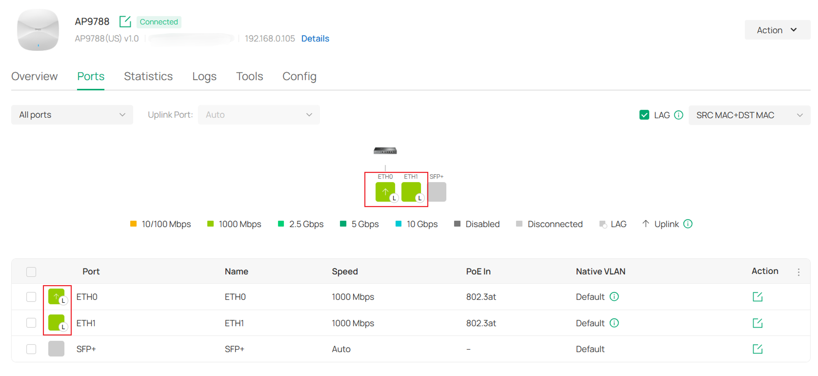
Note: When LAG is enabled, member ports use the VLAN setting of the LAG instead of their individual Port VLAN settings. Previous Port VLAN settings are retained and will be restored after LAG is disabled.
In Standalone Mode:
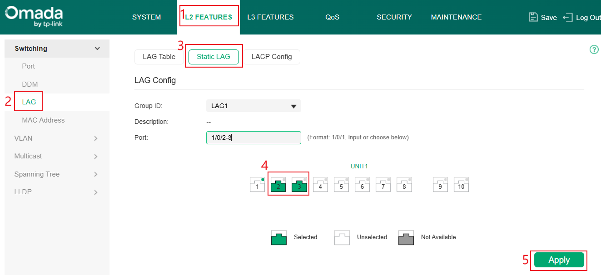
For Switches, navigate to L2 Features > LAG > Static LAG, select the desired LAG group and member ports, then click Apply to save the configuration.
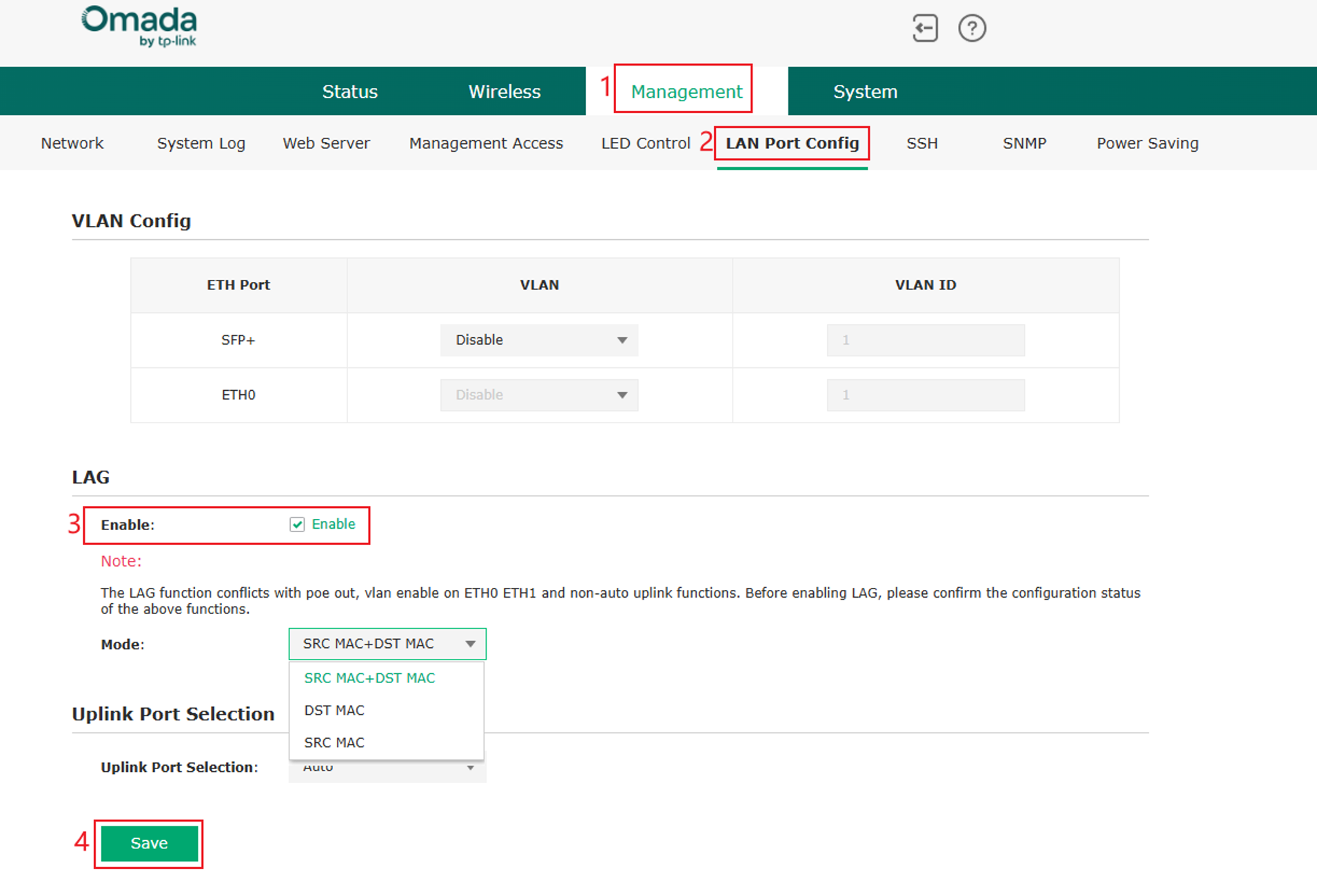
For APs, Go to Management > LAN Port Config and enable LAG. The default LAG mode is recommended for most deployment scenarios.
Note: LAG cannot be used simultaneously with PoE Out, VLAN Enable on ETH0/ETH1, or Non-Auto Uplink. Verify the configuration of these features before enabling LAG.
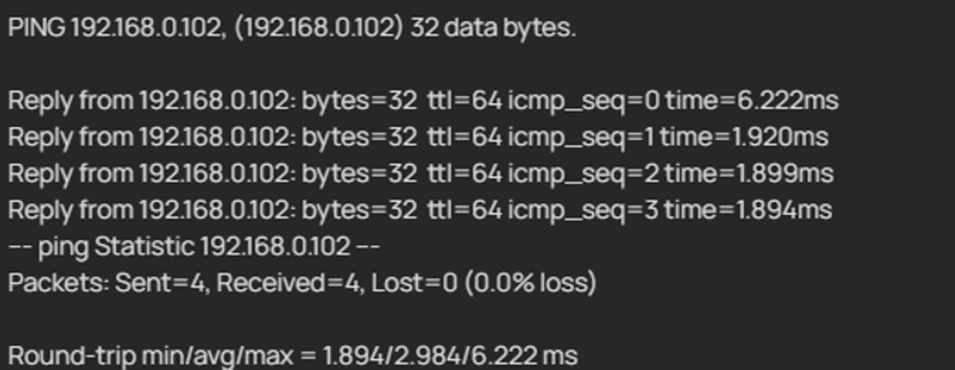
If you would like to verify that the LAG has been established successfully, you can ping the switch from a client connected to the AP. If there is no packet loss, it indicates that the LAG link is operating properly.
Q6: Does Dual PoE support hot plugging? Will the AP reboot if one PoE cable is disconnected during operation?
A6: In most cases, the AP continues operating when one PoE connection is removed, provided the remaining power source can supply sufficient power.
However, device behavior depends on the resulting power level after the disconnection:
- The AP will automatically detect the new power condition and adjust available features accordingly.
- If power falls below the required operating level, the AP may disable certain functions such as wireless radios, Ethernet ports, USB, SFP, or scan radio functions.
- In some scenarios, such as transitioning from a high-power configuration (for example, 802.3bt + 802.3af) to single 802.3af, the AP may temporarily consume more power than the remaining source can provide. In this case, a reboot may occur while the device re-detects the power source and applies the appropriate power-saving restrictions.
Q7: Does Dual PoE improve wireless performance?
A7: No. The primary purposes of Dual PoE are:
- Providing sufficient power for high-power APs.
- Providing power redundancy.
- Providing network link redundancy.
When the AP receives adequate power, Dual 802.3at, Single 802.3bt, and DC power deliver the same wireless performance. Dual PoE does not increase wireless throughput beyond the AP's designed specifications.
However, insufficient power may limit AP performance:
- 802.3af + 802.3at: 4×4 MIMO is maintained, but maximum transmit power is reduced.
- Single 802.3at or Dual 802.3af: The AP operates in 2×2 MIMO mode, reducing wireless capacity and performance.
