


Power Sourcing Equipment (PSE)-First
Solutions of Common PoE Topologies
Scenario #1: PoE Switch and PoE Injector/Adapter + Powered Devices
Scenario #2: PoE Extender + Powered Devices
Scenario #3: PoE Splitter + Powered Devices
Introduction
This article describes how to design and configure a Power over Ethernet (PoE) network within the Omada ecosystem. PoE technology allows a single Ethernet cable to provide both data connection and electric power to devices such as Access Points (EAPs), IP Cameras (IPCs), VoIP Phones, Audio/Video Gear, and IoT Devices, simplifying installation and reducing cabling costs.
PoE Standards
|
Standard |
Max per Port (PSE) |
Realistic Output (PD) |
|
802.3af (PoE) |
15.4 W |
12.95 W |
|
802.3at (PoE+) |
30 W |
25.5 W |
|
802.3bt (Tier 3 PoE++) |
60 W |
51 W |
|
802.3bt (Tier 4 PoE++) |
90 W |
71.3 W |
How to Choose PoE Devices
There are two primary methods for choosing your PoE hardware.
Note: When choosing PoE hardware, it is important to remember that some power dissipates in the cable. To avoid this, when managing the PoE budget for your network, it’s best to leave a 10-15% margin to power your devices.
Powered Device (PD)-First
Select a PD (e.g. access point) based on coverage needs, then choose a PSE (e.g. PoE switch) that supports the specific PoE standard and total power requirements.
For example, let’s say there are four PoE+ (802.3at) APs that output 30W each:
4 APs x 30W = 120W
The PSE will need to provide at least 138W of minimum PoE budget:
120W x 1.15 (applying 15% margin) = 138W
In this example, with four PoE+ access points, a minimum 138W PoE+ Switch would work well if no more PDs were added to the network.
Note: It is common to purchase a higher PoE budget switch than is currently needed, such as a 250W PoE Switch in case more powered devices are purchased in the future.
Power Sourcing Equipment (PSE)-First
If there is already a PSE device in place, ensure it matches the PoE standard (802.3af/at/bt) found in the device specifications when choosing a PD.
Within the Omada ecosystem, the PoE Standard (802.3af/at/bt) and the power requirements can be found within the device specifications or directly on the hardware labels, though the location varies between device types.
For example, let’s say there is a 250W PoE+ Switch that supports a total 250W budget. The user is thinking about purchasing eight PoE access points that output 30W each.
8 APs x 30W = 240W
The total output of all eight APs will be 240W and the total budget of the PoE+ Switch is 250W. While this fits under the total PoE budget, it does not allow for the 10-15% margin:
240W / 250W = 4% margin
It would be best to purchase seven APs instead, which allows for the 10-15% margin:
7 APs x 30W = 210W
210W / 250W = 16% margin
In this example, with a PoE+ Switch that supports a total 250W budget, purchasing seven PoE or PoE+ access points outputting 30W each would be best instead of eight.
Note: Always match the PoE class and standard between the PSE and PD. While higher standards (like PoE++ 802.3bt) are typically backward compatible with lower-power devices, a mismatch in the opposite direction will result in insufficient power delivery.
Solutions of Common PoE Topologies
Here are some configurations of common PoE topologies.
Scenario #1: PoE Switch and PoE Injector/Adapter + Powered Devices
Network Topology
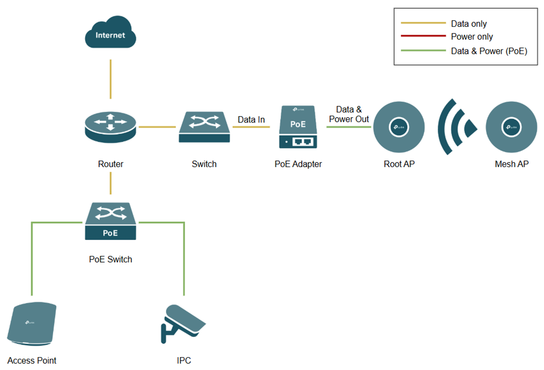
This topology involves a centralized PoE switch for wired devices and PoE adapters for Mesh EAPs.
PoE Switch to Powered Devices
The PoE switch connects to the router’s LAN port and connects powered devices (e.g. EAP or IPC) to the PoE ports on the switch.
Note: Check the "PoE Budget" in the PoE switch properties to ensure the total wattage of all connected PDs does not exceed the PoE switch's capacity.
PoE Adapter to Powered Devices
The PoE injector/adapter connects to the non-PoE switch LAN port via the “Data In” port and connects to powered devices via the “Data & Power Out” port.
Note: If your Omada device (such as certain outdoor EAPs) includes a proprietary passive PoE adapter in the box, it is highly recommended to use that specific adapter. Passive PoE does not negotiate voltage like standard PSE and providing incorrect voltage can permanently damage your hardware.
Scenario #2: PoE Extender + Powered Devices
Network Topology
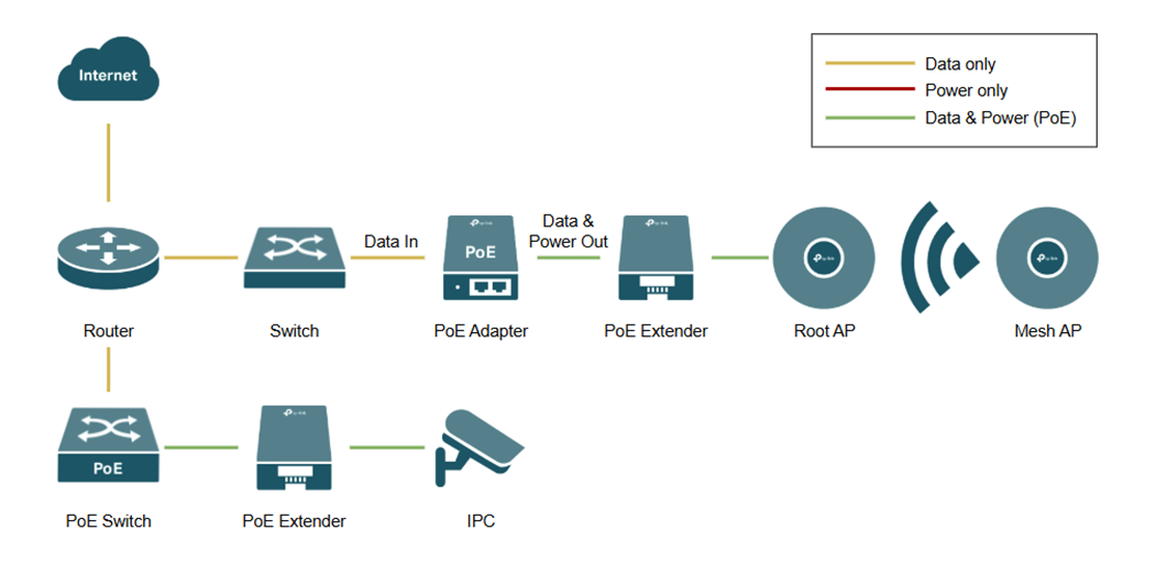
PoE extenders, also known as PoE repeaters, expand the range of PoE capable Ethernet cables beyond the standard 100 meters. This topology involves connecting a PoE extender to Power Sourcing Equipment (PSE) such as a PoE switch and PoE adapter.
PoE Switch to PoE Extender
The PoE switch uplinks to the router’s LAN port and distributes power and data via a PoE extender to downstream devices, such as IP cameras.
Non-PoE Switch to PoE Extender
The non-PoE switch uplinks to the router and feeds data into a PoE adapter/injector. This adapter adds power to the line, which is then carried through a PoE extender to support downstream devices like access points.
Note: While PoE extenders can be "daisy-chained" to reach distances beyond 200 meters, each additional hop introduces voltage drop and increased latency. For critical or high-bandwidth applications, such as high-resolution IP cameras or access points, limit the number of extenders to maintain signal integrity and power stability.
Scenario #3: PoE Splitter + Powered Devices
Network Topology
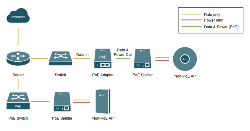
PoE splitters allow non-PoE compatible devices to be powered by a PoE network. This topology demonstrates how to bridge the gap between Power Sourcing Equipment (PSE), such as PoE switches or adapters, and non-PoE end-point devices like standard IP cameras.
PoE Switch to Non-PoE Device
The PoE switch uplinks to the router’s LAN port and transmits both power and data over a single Ethernet cable. A PoE splitter is placed at the end of the run to divide the combined signal back into two separate connections: a DC power jack and a standard RJ45 data plug, which connect to the non-PoE IPC.
Non-PoE Switch via PoE Adapter/Injector
For networks using a standard (non-PoE) switch, the data stream is first sent to a PoE adapter/injector. This adapter "injects" power into the Ethernet line. A PoE splitter is then used downstream to separate the power and data once again, providing the necessary inputs for a non-PoE IPC or other non-PoE hardware.
Note: When using a PoE splitter, ensure the DC output voltage of the splitter (e.g., 5V, 9V, or 12V) matches the specific power requirements of your non-PoE device. Using the wrong voltage can result in hardware damage or failure.
Conclusion
We have successfully set up a PoE network using PoE switches, adapters, extenders, and splitters.
QA
Q1: Can I plug a non-PoE device (like a laptop) directly into a PoE switch port?
A1: Yes. Most modern Omada PoE switches are "Active PoE" (802.3af/at/bt). They perform a "handshake" to detect if a connected device requires power. If the device is non-PoE, the switch will only send data, ensuring your hardware is safe from electrical damage.
Q2: What is the maximum distance I can run a PoE cable without an extender?
A2: The standard limit for Ethernet cabling is 100 meters. Beyond this distance, signal degradation and voltage drop occur. To go further, you must use a PoE extender.
Q3: Can I use a PoE Splitter and a PoE Extender in the same cable run?
A3: Yes. You can use an extender to reach a distant location and then place a splitter at the end of that run to power a non-PoE device. However, ensure your Power Sourcing Equipment (PSE) provides enough wattage (such as PoE+ 802.3at) to compensate for the combined power draw of both the extender and the splitter.
Get to know more details of each function and configuration please go to Download Center to download the manual of your product.
