


About this Guide
This User Guide provides information for centrally managing Omada devices via the Omada SDN Controller. Please read this guide carefully before operation.
Intended Readers
This User Guide is intended for network managers familiar with IT concepts and network terminologies.
Conventions
When using this guide, notice that:
· Features available in the Omada SDN Controller may vary due to your region, controller type and version, and device model. All images, steps, and descriptions in this guide are only examples and may not reflect your actual experience.
· The information in this document is subject to change without notice. Every effort has been made in the preparation of this document to ensure accuracy of the contents, but all statements, information, and recommendations in this document do not constitute the warranty of any kind, express or implied. Users must take full responsibility for their application of any products.
· This guide uses the specific formats to highlight special messages. The following table lists the notice icons that are used throughout this guide.
In this guide, the following conventions are used:
|
Controller |
Stands for the Omada On-Premises Controller and the Omada Cloud-Based Controller. |
|---|---|
|
On-Premises Controller |
Includes the Omada Software Controller (also referred to as the Omada Network Application), Omada Hardware Controller, and Omada Integrated Gateway (Controller). |
|
Cloud-Based Controller / Omada Central |
The Omada Cloud-Based Controller is now referred to as the Omada Network system on the Omada Central. Note that the Omada Central integrates the Omada Network system and Omada Guard system. The Omada Network system works as an Omada Controller to manage network devices (gateways, switches, access points, OLTs, and more), while the Omada Guard system works as a VMS system to manage surveillance devices (security cameras, NVRs, and more). This guide involves instructions about the Omada Network system. For instructions about the Omada Guard system, refer to the Omada Guard User Guide. |
|
Gateway/Router |
Stands for the Omada Gateway/Router. |
|
Switch |
Stands for the Omada Switch. |
|
AP |
Stands for the Omada AP. |
|
OLT |
Stands for the DeltaStream GPON Optical Line Terminal. |
|
Note: |
The note contains the helpful information for a better use of the controller. |
|
Configuration Guidelines: |
Provide guidelines for the feature and its configurations. |
More Resources
|
Main Site |
|
|---|---|
|
Video Center |
|
|
Documents |
|
|
Product Support |
|
|
Technical Support |
For technical support, the latest software, and management app, visit https://support.omadanetworks.com/.
Omada SDN Solution Overview
Omada SDN (Software-defined Networking) Solution offers centralized and efficient management for configuring enterprise networks comprised of gateways, switches, wireless access points, OLTs (Optical Line Terminals), and more via the On-Premises Controller as well as the Omada Central.
With a reliable network management platform powered by Omada, you can develop comprehensive, software-defined networking across demanding, high-traffic environments with robust wired and wireless solutions.
Overview
Omada SDN Solution is designed to provide business-class networking solutions for demanding, high-traffic environments such as campuses, hotels, malls, and offices. It simplifies deploying and managing large-scale enterprise networks and offers easy maintenance, ongoing monitoring, and flexible scalability.
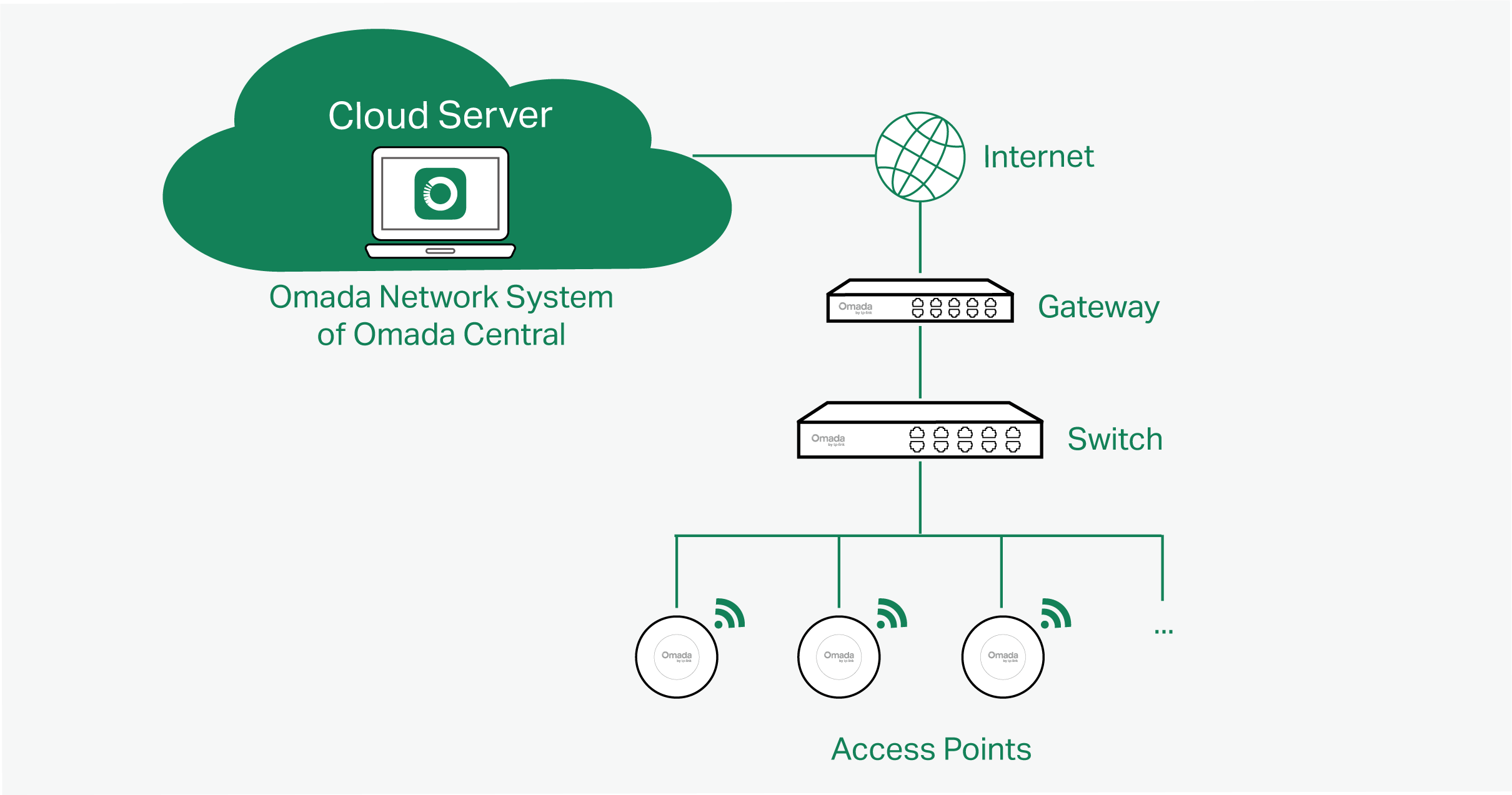
This figure shows a sample architecture of an SDN enterprise network:

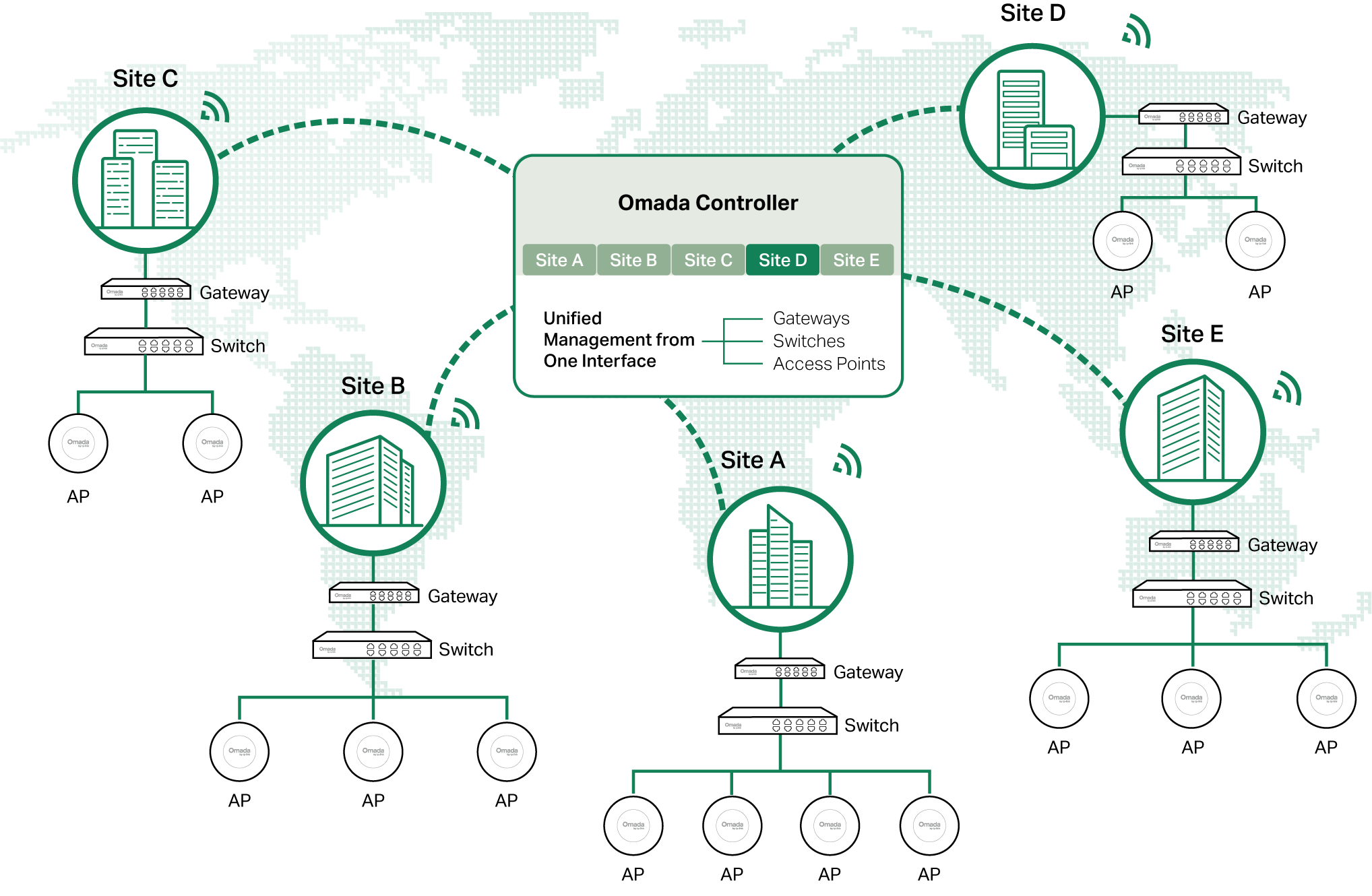 The interconnected elements that work together to deliver a unified enterprise network include: Controller, gateways, switches, access points, and client devices. Beginning with a base of client devices, each element adds functionality and complexity as the network is developing, interconnecting with the elements above and below it to create a comprehensive, secure wired and wireless solution.
The Controller is a command center and management platform at the heart of the network. With a single platform, the network administrators configure and manage enterprise networks comprised of gateways, switches, and wireless access points in batches. This unleashes new levels of management to avoid complex and costly over-provisioning.
Core Components
An SDN network consists of the following core components:
■ Controller — A command center and management platform at the heart of network solution for the enterprise. With a single platform, the network administrators configure and manage all Omada products which have all your needs covered in terms of routing, switching and Wi-Fi.
■ Gateways — Boast excellent data processing capabilities and an array of powerful functions, including IPsec/OpenVPN/PPTP/L2TP VPN, Load Balance, and Bandwidth Control, which are ideal for the business network where a large number of users require a stable, secure connection.
■ Switches — Offer flexible and cost-effective network solution with powerful Layer 2 features and PoE options. Advanced features such as Access Control, QoS, LAG and Spanning Tree will satisfy advanced business networks.
■ Access Points — Satisfy the mainstream Wi-Fi Standard and address your high-density access needs with Omada’s innovation to help you build the versatile and reliable wireless network for all business applications.
■ OLTs — Work with GPON APs to enable rapid optical network construction. Leveraging OLTs with single PON ports and optical splitters, GPON APs provide excellent scalability and enable high-density device management.
Controller
Tailored to different needs and budgets, Omada Controller offers diverse deployment solutions. Software Controller, Hardware Controller, and Cloud-Based Controller each has their own set of advantages and applications. The controllers differ in forms, but they have almost the same browser–based management interface and serve the same functions of network management.
For more information about the Omada Controller, refer to https://www.omadanetworks.com/business-networking/omada/controller/.
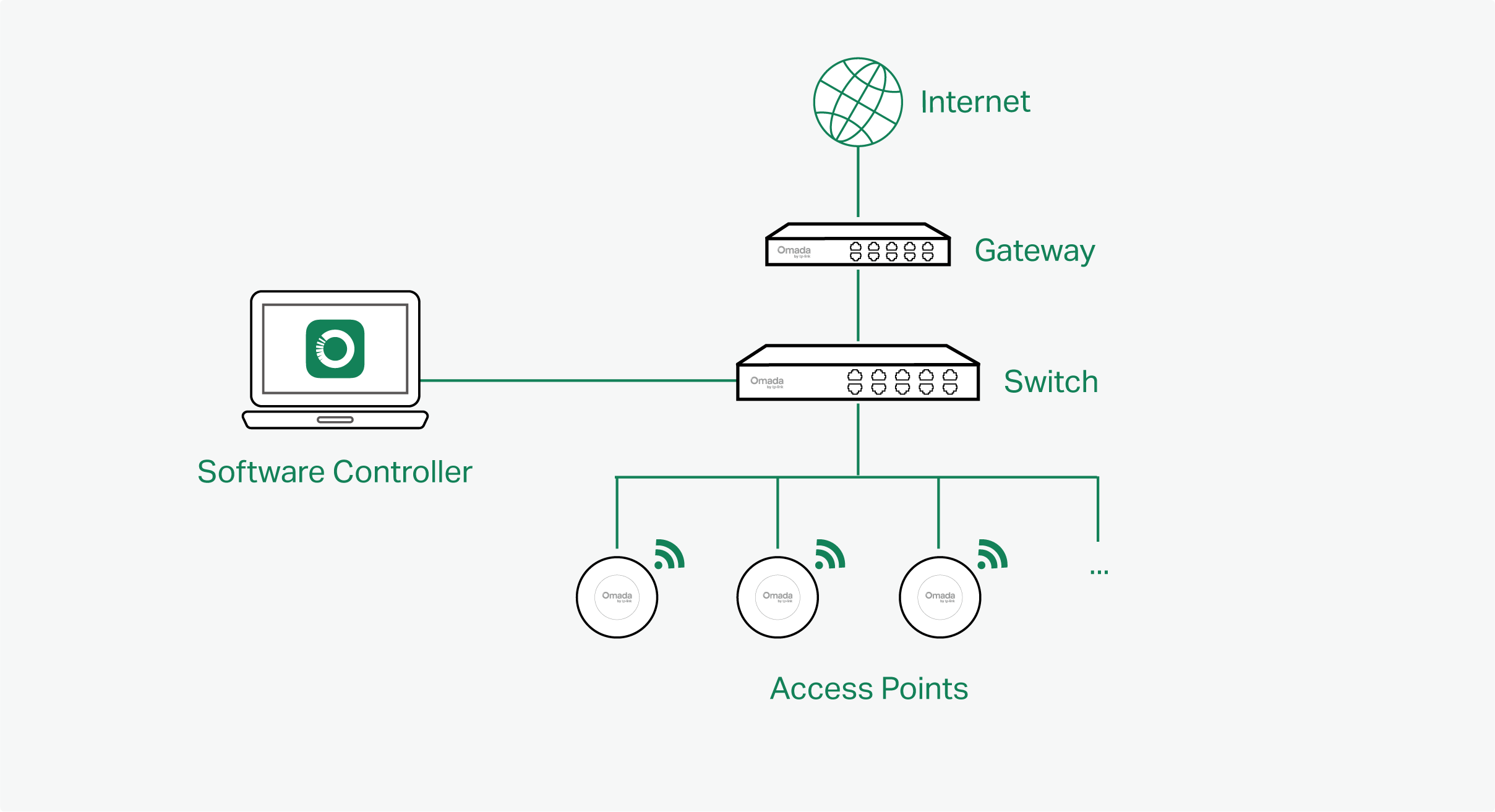
■ Software Controller
Software Controller can be hosted on any computers with Windows or Linux systems on your network.

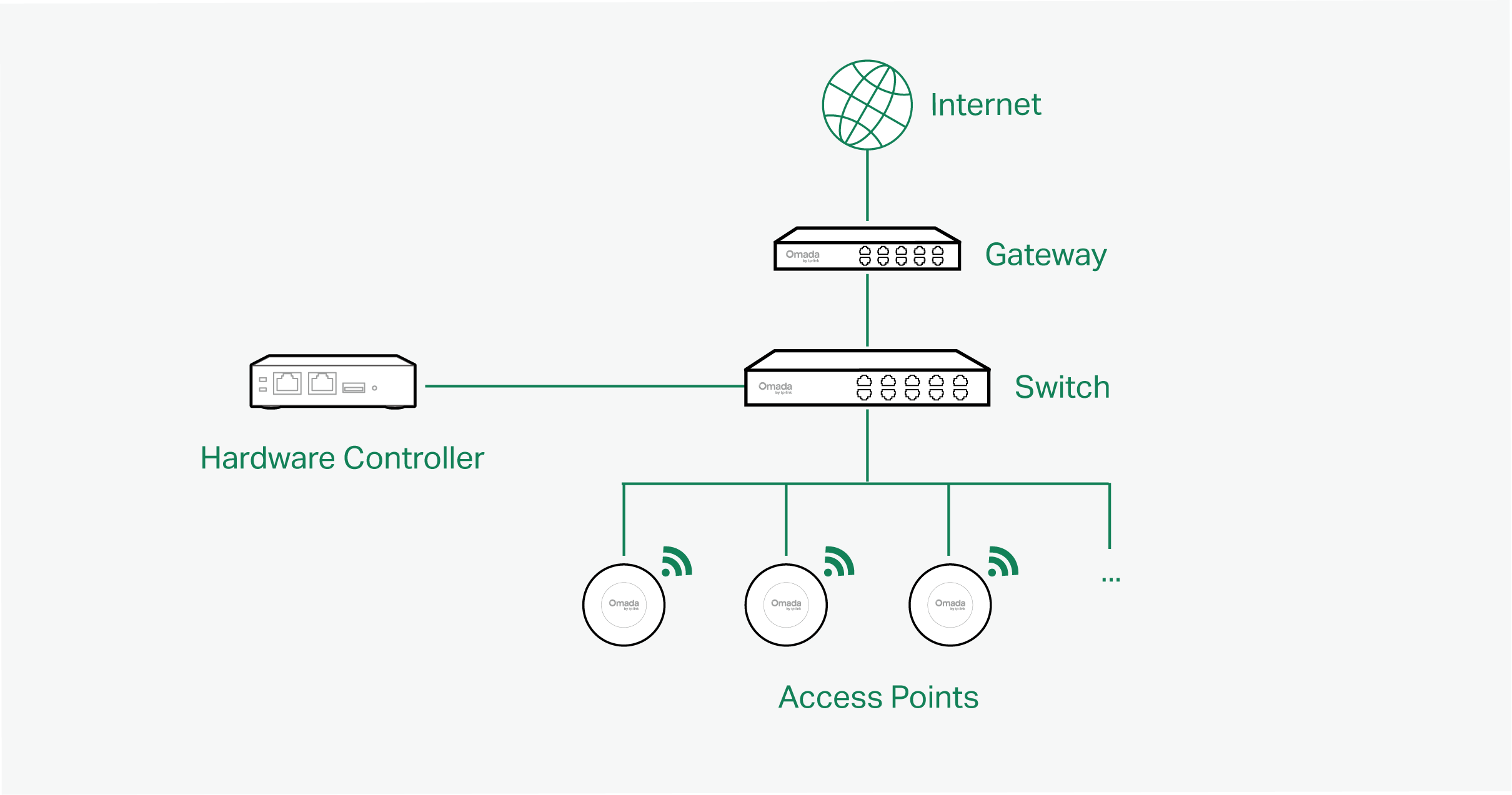
■ Hardware Controller
Hardware Controller is the management device which is pre-installed with the Software Controller. You just need to purchase the device, then the built-in software controller is ready to use. About the size of a mobile phone, the device is easy to deploy and install on your network.

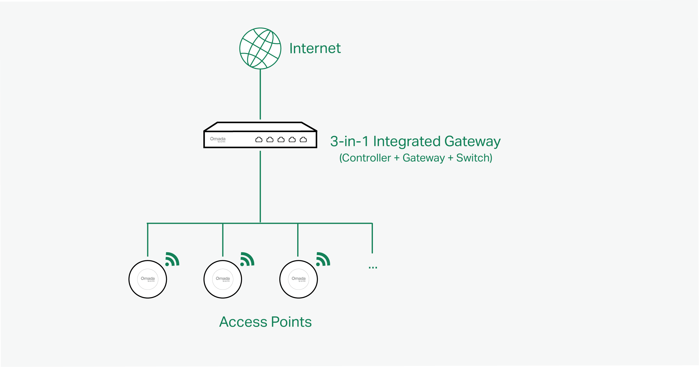
■ 3-in-1 Integrated Gateway (Controller)
3-in-1 Integrated Gateway integrates PoE+ ports and Controller ability. It is the management device which is pre-installed with the Software Controller. You just need to purchase the device, then the built-in software controller is ready to use. It can also work as the Gateway and Switch at the same time, allowing you to connect to access points and PoE-supported devices with ease.

■ Cloud-Based Controller (Omada Network System)
The Cloud-Based Controller is now referred to as the Network system on the Omada Central. It is deployed on the Omada Cloud server, providing the Essentials version for free management of essential features and the Standard version for basic and advanced features through subscription-based licensing.

Gateways
Omada Gateway supports Gigabit Ethernet connections on both WAN and LAN ports which keep the data moving at top speed. Including all the routing and network segmentation functions that a business gateway must have, VPN Gateway will be the backbone of the SDN network. Moreover, the gateway provides a secure and easy approach to deploy site-to-site VPN tunnels and access for remote clients.
Managing the gateway centrally through the Omada Controller is available on certain models only. For more information, refer to https://www.omadanetworks.com/omada-sdn/product-list/.
Switches
Omada Switch provides high-performance and enterprise-level security strategies and lots of advanced features, which is ideal access-edge for the SDN network.
Managing the switch centrally through the Omada Controller is available on certain models only. For more information, refer to https://www.omadanetworks.com/omada-sdn/product-list/.
Access Points
Omada Access Point provides business-class Wi-Fi with superior performance and range which guarantees reliable wireless connectivity for the SDN network.
Managing the access points centrally through the Omada Controller is available on certain models only. For more information, refer to https://www.omadanetworks.com/omada-sdn/product-list/.
OLTs
OLTs and GPON APs are commonly used in all-optical network deployments, especially for FTTH/FTTR applications. As the shift toward fiber-to-the-home and the phase-out of copper accelerates, the OLT + GPON AP combination is emerging as a preferred enterprise networking solution.
Managing the OLTs centrally through the Omada Controller is available on certain models only. For more information, refer to https://www.omadanetworks.com/omada-sdn/product-list/.
Getting Started with Omada Controller
This chapter guides you on how to get started with Omada Controller to configure the network. The controllers differ in forms, but they have almost the same browser–based management interface for network management. Therefore, they have almost the same initial setup steps, including building your network topology, deploying your controller, and logging in to the controller.
Set Up Your Software Controller
Overview
Omada Controller is designed for scalable networks. Deployments and configurations vary according to actual situations. Understanding your network requirements is the first step when planning to provision any project. After you have identified these requirements, follow the steps below to initially set up the Software Controller:
1) Determine the network topology.
2) Install the Software Controller.
3) Start and log in to the controller.
Determine the Network Topology
The network topology that you create for the controller varies depending on your business requirements. The following figure shows a typical topology for a high-availability use case.
Note:
When using the Omada Controller, we recommend that you deploy the full topology with Omada devices. If you use third-party devices, Omada Controller cannot discover and manage them.
Install the Software Controller on Windows Host
Omada Software Controller can be hosted on any computers with Windows systems on your network. Make sure your PC’s hardware and system meet the following requirements, then properly install the Software Controller.
■ Hardware Requirements
To guarantee operational stability, we recommend that you use the hardware which meets or exceeds the following specifications:
CPU: Intel Core i3-8100, i5-6500, or i7-4700 with 2 or more cores and 4 or more threads.
Memory: 16 GB RAM or more.
■ System Requirements
Operating System: Microsoft Windows 10/11/Server. (We recommend that you deploy the controller on a 64-bit operating system to guarantee the software stability.)
Web Browser: Google Chrome 107 (or above), Mozilla Firefox 106 (or above), or Microsoft Edge 106 (or above). It is recommended to use the latest version.
■ Install the Software Controller
Download the installation file of Software Controller from https://support.omadanetworks.com/download/software/omada-controller/. Then follow the instructions to install the controller. After a successful installation, the controller shortcut icon will be created on your desktop.
Install the Software Controller on Linux Host
Two versions of installation package are provided: .tar.gz file and .deb file. Both of them can be used in multiple versions of Linux operating system, including Ubuntu and Debian.
Make sure your PC’s hardware and system meet the following requirements, then choose the proper installation files to install the Software Controller.
■ Hardware Requirements
To guarantee operational stability, we recommend that you use the hardware which meets or exceeds the following specifications:
CPU: Intel Core i3-8100, i5-6500, or i7-4700 with 2 or more cores and 4 or more threads.
Memory: 16 GB RAM or more.
■ System Requirements
Operating System: 64-bit Linux operating system, including Ubuntu 20.04/22.04/24.04, and Debian 11/12. Only support x64 version.
Web Browser: Google Chrome 107 (or above), Mozilla Firefox 106 (or above), or Microsoft Edge 106 (or above). It is recommended to use the latest version.
■ Install the Software Controller
Download the installation file of Software Controller from https://support.omadanetworks.com/download/software/omada-controller/. Check the prerequisites and follow the steps based on your file version to install the controller.
• Prerequisites for installing
To successfully install the Software Controller, ensure that you have performed the following tasks before your installation:
1. Ensure that the Java Runtime Environment (JRE) has been installed in your system. The controller requires that the system has Java 17 installed. Download the file according to your operating system from https://www.java.com/download/linux_manual.jsp and follow the instructions to install the JRE. For Ubuntu 20.04 or above, you can use the command: apt-get install openjdk-17-jre-headless to get the Java 17 installed.
2. Ensure that MongoDB has been installed in your system. The controller works when the system runs MongoDB 3.6-8.0 LTS versions. Download the file according to your operating system from the https://www.mongodb.com/try/download and follow the instructions to install the MongoDB.
3. Ensure that you have jsvc and curl installed in your system before installation, which is vital to the smooth running of the system. If your system does not have jsvc or curl installed, you can install it manually with the command: apt-get install or yum install. For example, you can use the command: apt-get install jsvc or yum install jsvc to get jsvc installed. And if dependencies are missing, you can use the command: apt-get -f install to fix the problem.
• Install the .tar.gz file
1. Make sure your PC is running in the root mode. You can use this command to enter root mode:
sudo
2. Extract the tar.gz file using the command:
tar zxvf Omada_Controller_vx.x.x_linux_x64_targz.tar.gz
3. Install the Controller using the command:
sudo bash ./install.sh
• Install the .deb file
1. Make sure your PC is running in the root mode. You can use this command to enter root mode:
sudo
2. Install the .deb file using the command:
dpkg -i Omada_Controller_vx.x.x_linux_x64.deb
If dependencies are missing during the installation, you can use the command: apt-fix-broken install to fix the problem.
After installing the controller, use the following commands to check and change the status of the controller.
tpeap start — Start the controller.
tpeap stop — Stop running the Controller.
tpeap status — Show the status of Controller.
For more detailed information about the installation on Linux hosts, refer to How to install Omada Software Controller on Linux system.
Note:
• For installing the .tar.gz, if you want the controller to run as a user (it runs as root by default), modify the OMADA_USER value in bin/control.sh.
• To uninstall the controller, go to the installation path: /opt/tplink/EAPController, and run the command: sudo bash ./uninstall.sh.
• During uninstallation, you can choose whether to back up the database. The backup folder is /opt/tplink/eap_db_backup.
• During installation, you will be asked whether to restore the database if there is any backup database in the folder /opt/tplink/eap_db_backup.
Start and Log In to the Software Controller
Launch the Software Controller and follow the instructions to complete basic configurations, and then you can log in to the management interface.
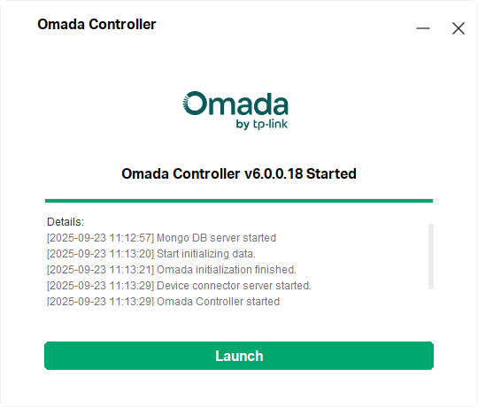
Launch the Software Controller
Double-click the controller shortcut icon and the following window will pop up. After a while, your web browser will automatically open.

Note:
• If your browser does not open automatically, click Launch. You can also launch a web browser and enter http://127.0.0.1:8088 in the address bar.
• If your web browser opens but prompts a problem with the website’s security certificate, click Continue.
Complete Basic Configurations
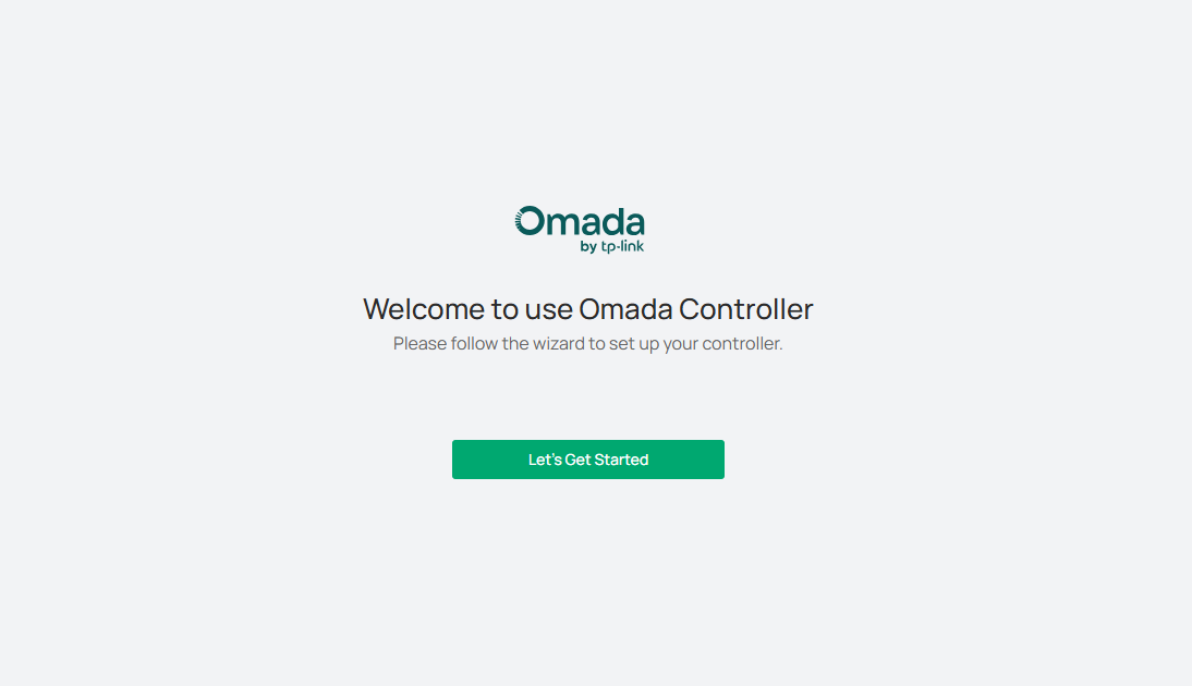
In the web browser, you can see the configuration page. Follow the setup wizard to complete the basic settings for the Controller.
1. Click Let’s Get Started.

2. Set up controller access settings.

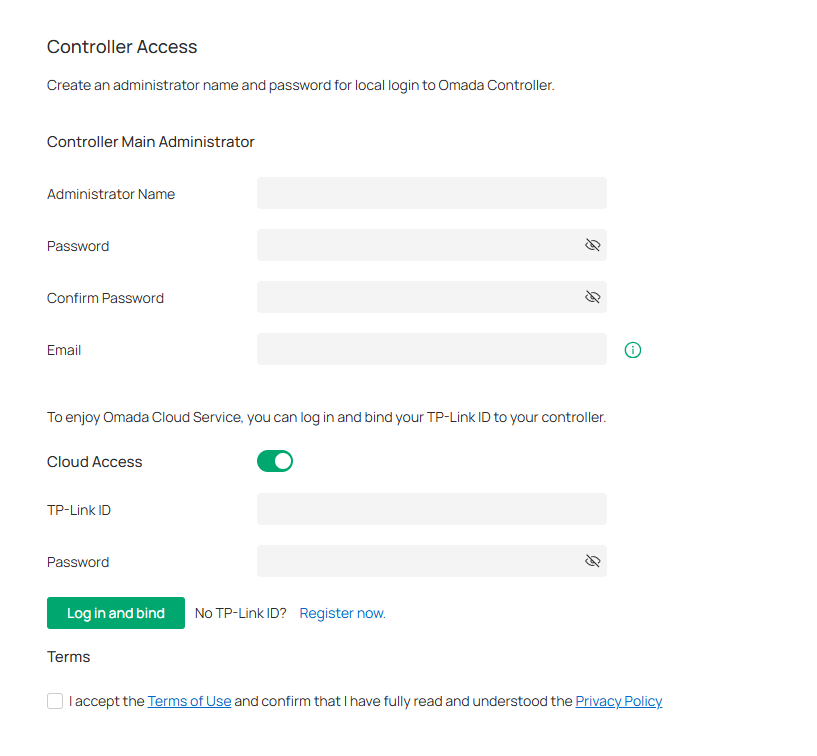
a. Create an Administrator username and password for login to the controller. Specify the email address for resetting your password in case that you forget the password. After logging into the Controller, set a mail server so that you can receive emails and reset your password. For instructions about how to set a mail server, refer to the Mail Server section.
b. If you want to access the controller to manage networks remotely, enable Cloud Access, and bind your TP-Link ID to your controller.
c. Read and agree to the Terms of Use.
d. Click Next.
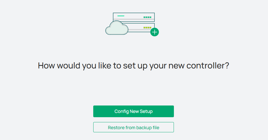
3. Choose how would you like to set up your new controller. You can configure a new setup or restore from backup file.

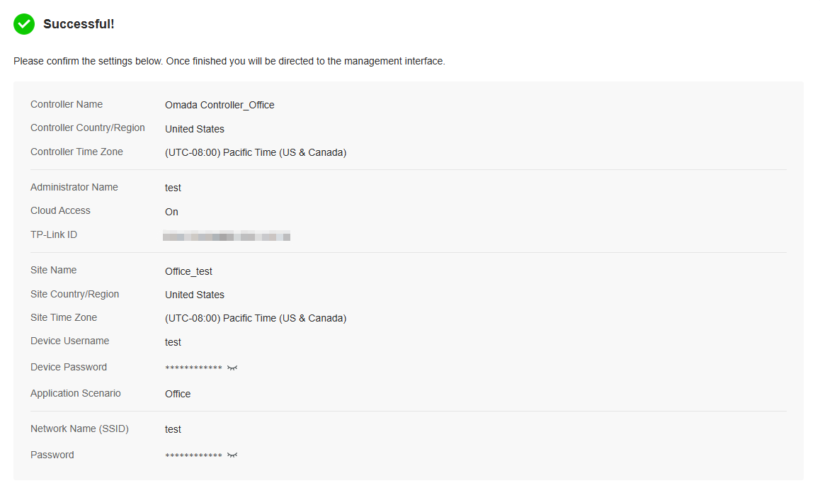
4. Follow the setup wizard to set up the controller.

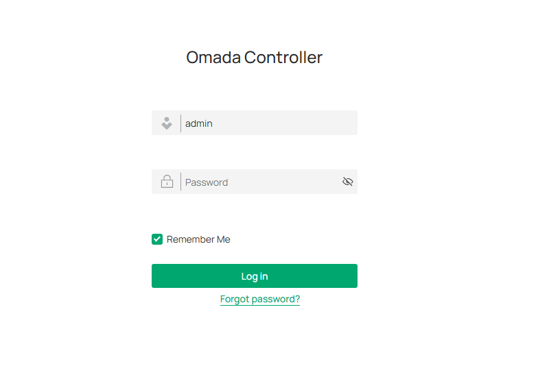
Log In to the Management Interface
Once the basic configurations are finished, the browser will be redirected to the following page. Log in to the management interface using the username and password you have set in the basic configurations.

Note:
In addition to the Controller Host, other hosts in the same LAN can also manage EAPs via remote access to the Controller Host. For example, if the IP address of the Controller Host is 192.168.0.100 and the Controller is running normally on this host, you can enter https://192.168.0.100:8043, or http://192.168.0.100:8088 in the web browser of other hosts in the same LAN to log in to the the Controller and manage EAPs. Or you can log in to the Controller using other management devices through Cloud service.
Set Up Your Hardware Controller
Overview
Omada Controller is designed for scalable networks. Deployments and configurations vary according to actual situations. Understanding your network requirements is the first step when planning to provision any project. After you have identified these requirements, follow the steps below to initially set up the Hardware Controller:
1) Determine the network topology.
2) Deploy the Hardware Controller.
3) Start and log in to the controller.
Determine the Network Topology
The network topology that you create for the controller varies depending on your business requirements. The following figure shows a typical topology for a high-availability use case.

Note:
When using the Omada Controller, we recommend that you deploy the full topology with Omada devices. If you use third-party devices, Omada Controller cannot discover and manage them.
Deploy the Hardware Controller
Omada Hardware Controller comes with the pre-installed controller software, so installation is not necessary. After deploying the Hardware Controller on your network infrastructure, proceed to configure the controller.
Start and Log in to the Controller
Log In to the Management Interface
Follow the steps below to enter the management interface of the Hardware Controller:
1. Make sure that your management device has the route to access the controller.
2. Check the DHCP server (typically a router) for the IP Address of the controller. If the controller fails to get a dynamic IP address from the DHCP server, the default fallback IP address 192.168.0.253, is used.
3. Launch a web browser and type the IP address of the controller in the address bar, then press Enter (Windows) or Return (Mac).
Complete Basic Configurations
In the web browser, you can see the configuration page. Follow the setup wizard to complete the basic settings for the Controller.
1. Click Let’s Get Started.
2. Set up controller access settings.
a. Create an Administrator username and password for login to the controller. Specify the email address for resetting your password in case that you forget the password. After logging into the Controller, set a mail server so that you can receive emails and reset your password. For instructions about how to set a mail server, refer to the Mail Server section.
b. If you want to access the controller to manage networks remotely, enable Cloud Access, and bind your TP-Link ID to your controller.
c. Read and agree to the Terms of Use.
d. Click Next.
3. Choose how would you like to set up your new controller. You can configure a new setup or restore from backup file.
4. Follow the setup wizard to set up the controller.
Log In to the Management Interface
Once the basic configurations are finished, the browser will be redirected to the following page. Log in to the management interface using the username and password you have set in the basic configurations.
Note:
In addition to the Controller Host, other hosts in the same LAN can also manage EAPs via remote access to the Controller Host. For example, if the IP address of the Controller Host is 192.168.0.100 and the Controller is running normally on this host, you can enter https://192.168.0.100:8043, or http://192.168.0.100:8088 in the web browser of other hosts in the same LAN to log in to the the Controller and manage EAPs. Or you can log in to the Controller using other management devices through Cloud service.
Set Up Your Integrated Gateway (Controller)
Overview
Omada Controller is designed for scalable networks. Deployments and configurations vary according to actual situations. Understanding your network requirements is the first step when planning to provision any project. After you have identified these requirements, follow the steps below to initially set up the Integrated Gateway (Controller):
1) Determine the network topology.
2) Deploy the Integrated Gateway (Controller).
3) Start and log in to the controller.
Determine the Network Topology
The network topology that you create for the controller varies depending on your business requirements. The following figure shows a typical topology for a high-availability use case.
Note:
When using the Omada Controller, we recommend that you deploy the full topology with Omada devices. If you use third-party devices, Omada Controller cannot discover and manage them.
Deploy the Integrated Gateway (Controller)
Omada Integrated Gateway (Controller) comes with the pre-installed controller software, so installation is not necessary. After deploying the Integrated Gateway (Controller) on your network infrastructure, proceed to configure the controller.
Start and Log in to the Controller
Log In to the Management Interface
Follow the steps below to enter the management interface of the Integrated Gateway (Controller):
1. Connect a computer to a LAN port of the Integrated Gateway (Controller) with an RJ45 port properly. If your computer is configured with a fixed IP address, change it to obtain an IP address automatically.
2. Launch a web browser and type the default management address 192.168.0.1 in the address bar, then press Enter (Windows) or Return (Mac). The management interface will start up.
Complete Basic Configurations
In the web browser, you can see the configuration page. Follow the setup wizard to complete the basic settings for the Controller.
1. Click Let’s Get Started.
2. Set up controller access settings.
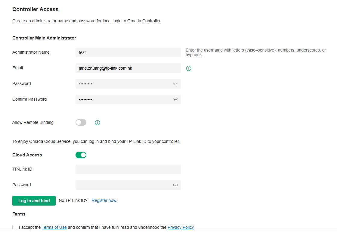
a. Create an Administrator username and password for login to the controller. Specify the email address for resetting your password in case that you forget the password. After logging into the Controller, set a mail server so that you can receive emails and reset your password. For how to set a mail server, refer to the Mail Server section.
b. If you want to allow the device to connect to the cloud portal remotely, enable Allow Remote Binding.
c. If you want to access the controller to manage networks remotely, enable Cloud Access, and bind your TP-Link ID to your Controller.
d. Read and agree to the Terms of Use.
e. Click Next.
3. Choose how would you like to set up your new controller. You can configure a new setup or restore from backup file.
4. Follow the setup wizard to set up the controller.
Log In to the Management Interface
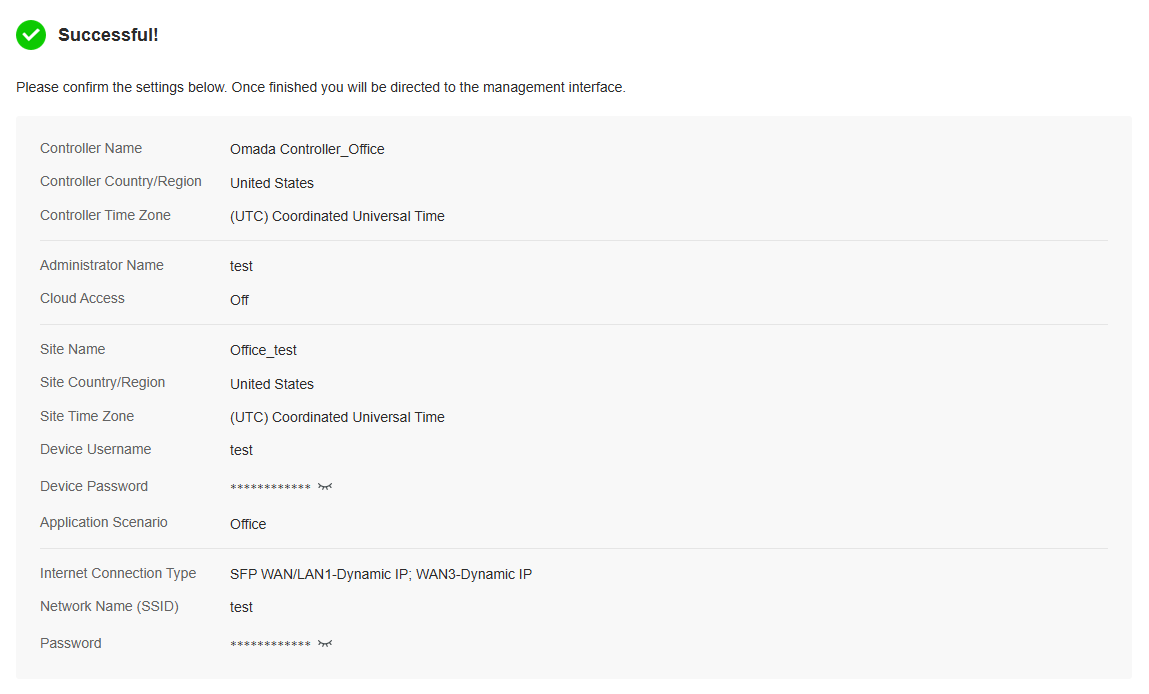
Once the basic configurations are finished, the browser will be redirected to the following page. Log in to the management interface using the username and password you have set in the basic configurations.
Set Up Your Cloud-Based Controller
Overview
The Omada Cloud-Based Controller is now referred to as the Omada Network system on the Omada Central.
Omada Central integrates the Omada Network system and Omada Guard system. The Omada Network system works as an Omada Controller to manage network devices (gateways, switches, access points, OLTs, and more), while the Omada Guard system works as a VMS system to manage surveillance devices (security cameras, NVRs, and more). The Omada Central
Omada Central offers the Essentials version for easy and free management of essential features, and the Standard version for basic and advanced features through subscription-based licensing.
View the compatible device list below to see if your devices can be centrally managed by the Omada Central:
Essentials version: https://www.omadanetworks.com/omada-cloud-essentials/product-list/
Standard version: https://www.omadanetworks.com/omada-cloud-based-controller/product-list/
Set Up the Controller
To set up the Omada Central, follow the steps below:
1. Launch a web browser and enter https://omada.tplinkcloud.com in the address bar. Enter your TP-Link ID and password to log in. If you do not have a TP-Link ID, create a TP-Link ID first.
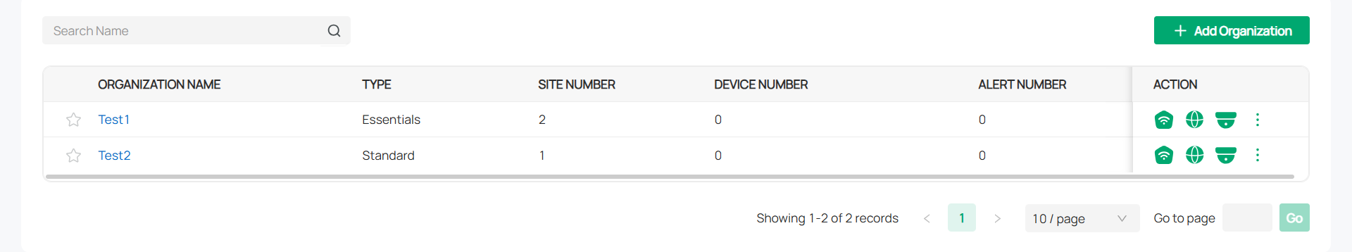
2. On the Cloud-Based Systems page, click Add Organization and choose the type of your organization.

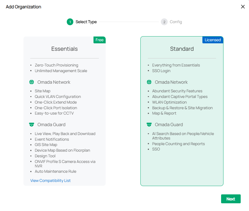
|
Essentials |
Select this type to create an Essentials organization for easy and free management of essential features. To check whether your devices can be managed by Omada Central Essentials, click View Compatibility List. |
|---|---|
|
Standard |
Select this type to create a Standard organization for basic and advanced features through subscription-based licensing. |
3. Follow the instructions to configure set up the organization.
Log In to the Management Interface
After creating an organization, you will automatically access the organization.
You can click the Organization drop-down list in the top left of the screen to manage the organization list or switch organizations.

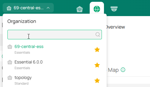
In the organization list, you can click an organization to access it.

 For more instructions, refer to the Omada Central Start Guide.
Navigate the Controller UI
As you start using the management interface of the controller (Controller UI) to configure and monitor your network, it is helpful to familiarize yourself with the Controller UI.
Note:
Features available in the Omada Controller may vary due to your region, controller type and version, and device model.
■ Global Overview
Know the status of your sites at a glance, and manage sites in the platform. The panel is divided into sections and placed in the order that you are most likely to use them when configuring and monitoring the network.
• Site Monitoring — Keep you informed of accurate, real-time status of every site.
• Site Management — Manage all sites to deploy the whole network.
• Account Settings — Manage all administrative accounts.

■ Site Overview
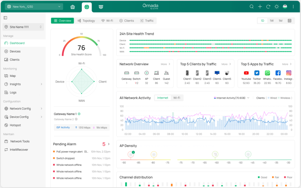
Know the status of your network at a glance, gain insights, and manage network devices all in the platform. By visualizing data, key information is presented on a single screen, allowing you to quickly understand the status and trends of your business.
• Statistics & Monitoring — Keep you informed of accurate, real-time status of every network device and client.
• Configuration — Configure all network devices, including network configuration, device configuration, and authentication.

■ Monitoring
Network administrators can monitor the status of all network devices and clients in real time. The system provides detailed connection statuses, data usage, and alert logs, ensuring the stability and security of network operations.

■ Configuration
Set up and manage network, device, and authentication configurations for the optimal overall network performance.
• Network Config — Manage and optimize network configurations to ensure efficient and secure network connections.
• Device Config — Centrally set up and manage device configurations by device type, improving device performance and stability.

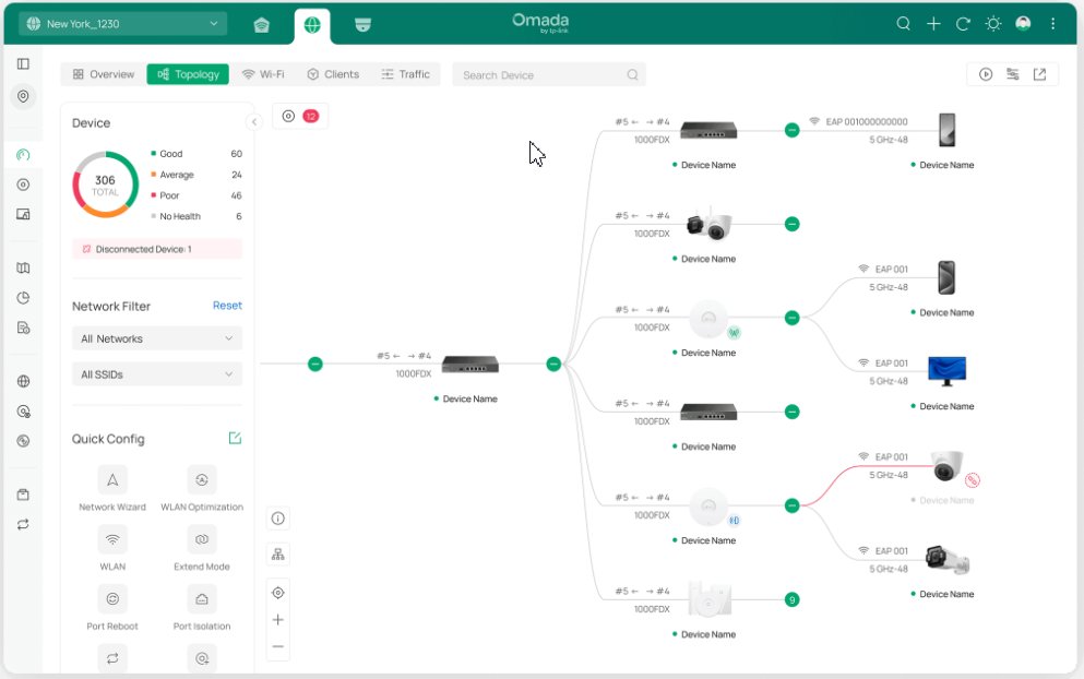
The Controller UI is grouped into task-oriented menus. These menus are located in the left-hand navigation bar of the page. Note that the settings and features that appear in the UI depend on your user account permissions. The following image depicts the main elements of the Controller UI.
■ Elements in top right corner
The elements in the top right corner of the screen give quick access to:


|
Global Search Feature |
Click the Search icon and enter the keywords to quickly look up the functions or devices that you want to configure. And you can search for the devices by their MAC addresses and device names. |
|---|---|
|
Refresh Page |
Click the Refresh icon to refresh the page. |
|
Theme Settings |
Change theme settings to light mode, dark mode, or system theme to improve your overall screen experience. |
|
My Account |
Click the Account icon to display account information, Account Settings and Log Out. You can change your password on Account Settings. |
|
More Settings |
Click the More icon for more settings. Feedback: Click to send your feedback to us. About: Click to display the controller info. Tutorial: Click to view the quick Getting Started guide which demonstrates the navigation and tools available for the controller. Old UI Layout/New UI Layout: Click to switch between the previous UI layout and the new UI layout. |
■ Navigation bar in the left
In Global View, the left-hand navigation bar provides access to:
|
Global/Site View drop-down list |
Allows you to access the Global View or access a site quickly. Global View: Know the status of your Site at a glance, and manage sites in the platform. Site View: Know the status of your network at a glance, gain insights, and manage network devices all in the platform. |
|---|---|
|
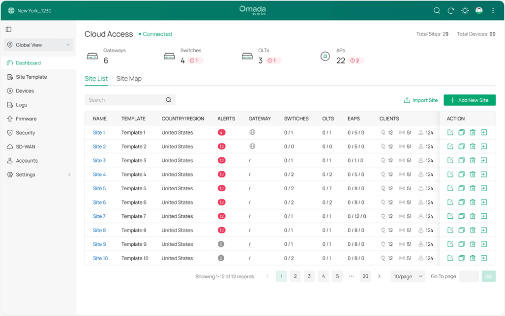
Dashboard |
Displays the sites in the organization and their status. You can switch between the site list view and site map view. |
|
Site Template |
Allows you to configure site templates and bind sites to them to facilitate batch configuration and management of sites. |
|
Devices |
Displays the devices on all sites and their general information. This list view can change depending on your monitoring need through customizing the columns. You can click any device on the list for device details and settings. |
|
Logs |
Displays the logs about systems events and devices. Comprehensive logs make historical information more accurate, readily accessible, and usable, which allows for proactive troubleshooting. And you can determine alert-level events and enable pushing notifications. |
|
Firmware |
Allows you to update the firmware of network devices in a one-time or periodic manner. |
|
Security |
Allows you to manage threats that the controller discovered to ensure network security. Note: This option will be hidden if no Omada device that supports this function is adopted. |
|
SD-WAN |
Allows you to easily connect multiple gateways together without complicated VPN configuration. Note: This option will be hidden if no Omada device that supports this function is adopted. |
|
Accounts |
Allows you to manage all administrative accounts of the controller. |
|
Settings |
Allows you to configure global settings in minutes and maintain the Omada network for best performance. |
In Site View, the left-hand navigation bar provides access to:
|
Global/Site View drop-down list |
Allows you to access the Global View or access a site quickly. Global View: Know the status of your Site at a glance, and manage sites in the platform. Site View: Know the status of your network at a glance, gain insights, and manage network devices all in the platform. |
|---|---|
|
Dashboard |
Displays a summarized view of the network status through different visualizations. The dashboard is a powerful tool that arms you with real-time data for monitoring the network. |
|
Devices |
Displays the devices in the site and their general information. This list view can change depending on your monitoring need through customizing the columns. You can click any device on the list for device details and settings. |
|
Clients |
Displays a list view of wired and wireless clients, IPCs, and NVRs that are connected to the network. This list view can change depending on your monitoring need through customizing the columns. You can click any entry on the list for more detailed information and settings. |
|
Map |
Displays the geographic location of each device and site in Device Map and Site Map. You can also upload images of your location for a visual representation of your network in Heat Map. |
|
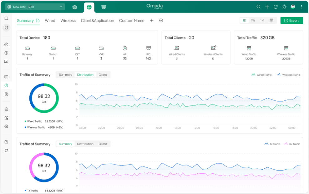
Insights |
Displays the statistics of various network indicators and their changes over time in Reports and detailed traffic information in Application Analytics. |
|
Logs |
Records the activities of the system, devices, users and administrators. Comprehensive logs make historical information more accurate, readily accessible, and usable, which allows for proactive troubleshooting. And you can determine alert-level events and enable pushing notifications. |
|
Network Config |
Allows you to manage and optimize network configurations to ensure efficient and secure network connections. |
|
Device Config |
Allows you to centrally set up and manage device configurations by device type, improving device performance and stability. |
|
Hotspot |
Allows you to centrally monitor and manage the clients authorized by portal authentication. |
|
Network Tools |
Provides various network tools for you to test the device connectivity, capture packets for troubleshooting, open Terminal to execute CLI or Shell commands, and perform cable tests. |
|
IntelliRecover |
Allows you to monitor the status of PoE devices, automatically repairing abnormal devices. |
Getting Started with Omada Network
Get started with your network on the Omada Controller by creating sites and adopting devices so that you can configure and monitor your devices centrally while keeping things organized.
Create Sites
Overview
Different sites are logically separated network locations, like different subsidiary companies or departments. It’s best practice to create one site for each LAN (Local Area Network) and add all the devices within the network to the site, including the router, switches and APs.

Devices at one site need unified configurations, whereas those at different sites are not relative. To make the best of a site, configure features simultaneously for multiple devices at the site, such as VLAN and PoE Schedule for switches, and SSID and WLAN Schedule for APs, rather than set them up one by one.
Configuration
To create and manage a site, follow these steps:
1) Create a site.
2) View and edit the site.
3) Access the site.
Step 1: Create a Site
To create a site, choose one from the following methods according to your needs.
1. Launch the controller and access the Global View.
2. Go to Dashboard > Site List and click Add New Site.

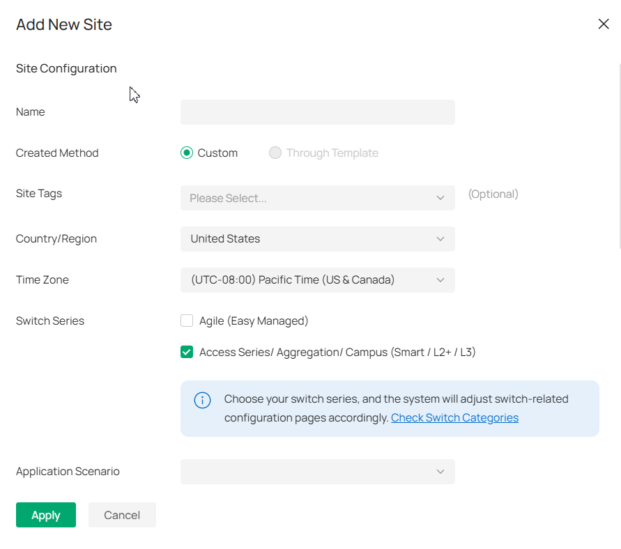
3. Enter a Site Name to identify the site, and configure other parameters according to actual site needs and location.
4.Create a device username and password for login to newly adopted devices.
5.Click Apply. The new site will be added to the Site List.
You can quickly create a site based on an existing one by copying its site configuration, wired configuration, and wireless configuration among others. After that, you can flexibly modify the new site configuration to make it different from the old.
1. In the Site List, click the Copy icon in the ACTION column of the site which you want to copy.

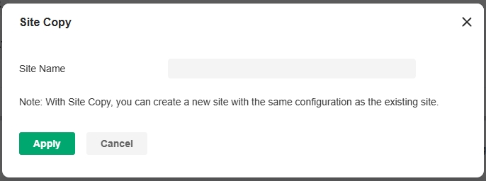
2. Enter a Site Name to identify the new site.
3. Click Apply. The new site will be added to the Site List.
■Import a site from another controller
If you want to migrate seamlessly from an old controller to a new one, import the site configuration file of the old controller into the new. Before that, you need to export the site configuration file from the old controller, which is covered in the Site Migration chapter in this guide.
1. In the Site List, click Import Site.

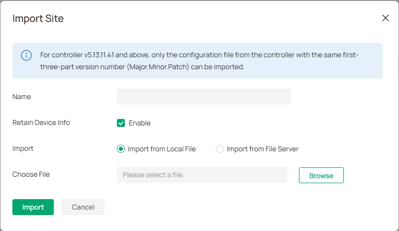
2. Enter a Site Name to identify the site, and configure other parameters according to actual site needs.
3. Browse your file explorer and choose a site configuration file.
4. Click Import. The new site will be added to the Site List.
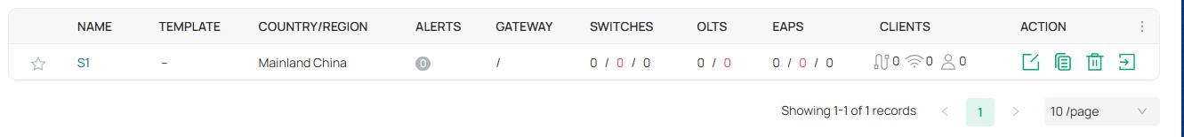
Step 2: View and Edit the Site
After you create the site, you can view the site status in the Site List. You can click the icons in the ACTION column to edit, copy, delete and launch the site.

Step 3: Access the Site
To monitor and configure a site, you need first access the site.
Click the Launch icon in the ACTION column of the site to access the site.
Alternatively, select the site from the Global/Site View drop-down list in the left of the page.
Note:
Configuration items in Global View will be applied to the whole system while configuration items in Site View will be applied to the site which you are currently in.
Configure the Site Template
Overview
The Site Template feature is implemented at the Controller's Global View to facilitate users to configure and manage sites in bulk. Most of the site's functions are supported to be set up in the Site Templates, such as Internet/LAN/WLAN/ACL/URL Filtering/Portal/MAC Authentication, etc. By binding each site to a different template, you can quickly and easily realize the batch configuration of a large number of sites. For example, if a Controller manages several different sites and needs to make bulk configuration changes for them for business changes or other reasons, you can create Site Templates ahead of time and then apply the target Site Templates directly to the sites to be changed without having to go into each site individually to make adjustments to them. The greater the number of sites, the more the feature will work.
In addition, you can also create Device Template in Site template, then choose to bind the devices with the same model to the related Device template after binding them to Site template, which greatly improves the efficiency of managing and configuring devices. For instance, a large number of SG3452XP v2.20 are deployed on the same site, but the configurations are not exactly the same, in this case, it's possible to create a Device Template for each configuration, i.e. to set up different Ports/VLAN interface/Static Route/Service settings, and then apply each Device Template to the required devices.
Configuration
1. Launch the controller and access the Global View.
2. Go to the Site Template page. Click Add New Site Template. Name the template and select the configurable modules according to your needs.
Note:
• Most of the site's Configurable Modules are supported to be set up in the Site Template, some of them are mandatory and some are optional (you can set them up only if they are selected here). Please refer to https://www.omadanetworks.com/support/faq/4341 to know all modules supported in Site Template feature in detail.
• After the Site Template is created, its configurable modules cannot be changed.

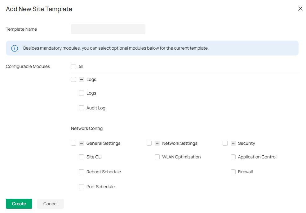
3. Click Create. The created site template will be displayed.


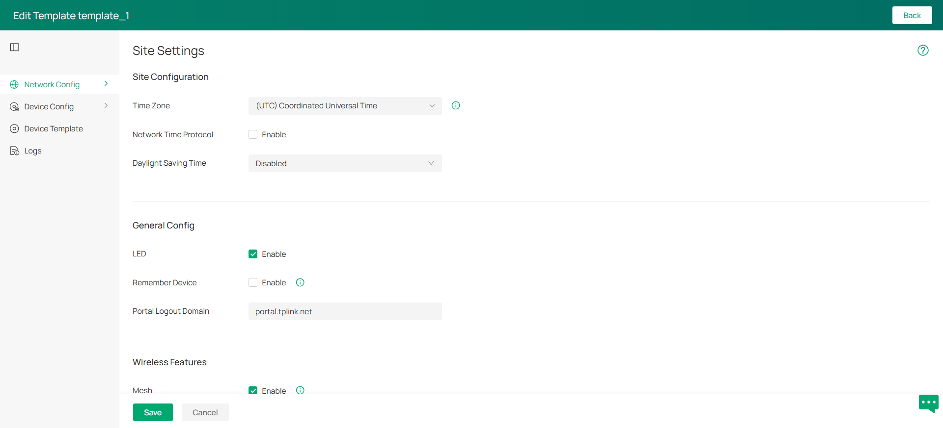
4. Click the edit icon in the Action column of the created site template, set up the network config, device config, and log settings according to site needs.
Note:
For configuration of the function modules, refer to the related chapters in this guide.

5. In Device Template, you can create a template for specific device type and model, then click the edit icon in the Action column of the created device template to set up device settings. Device template parameters vary by device type and model.

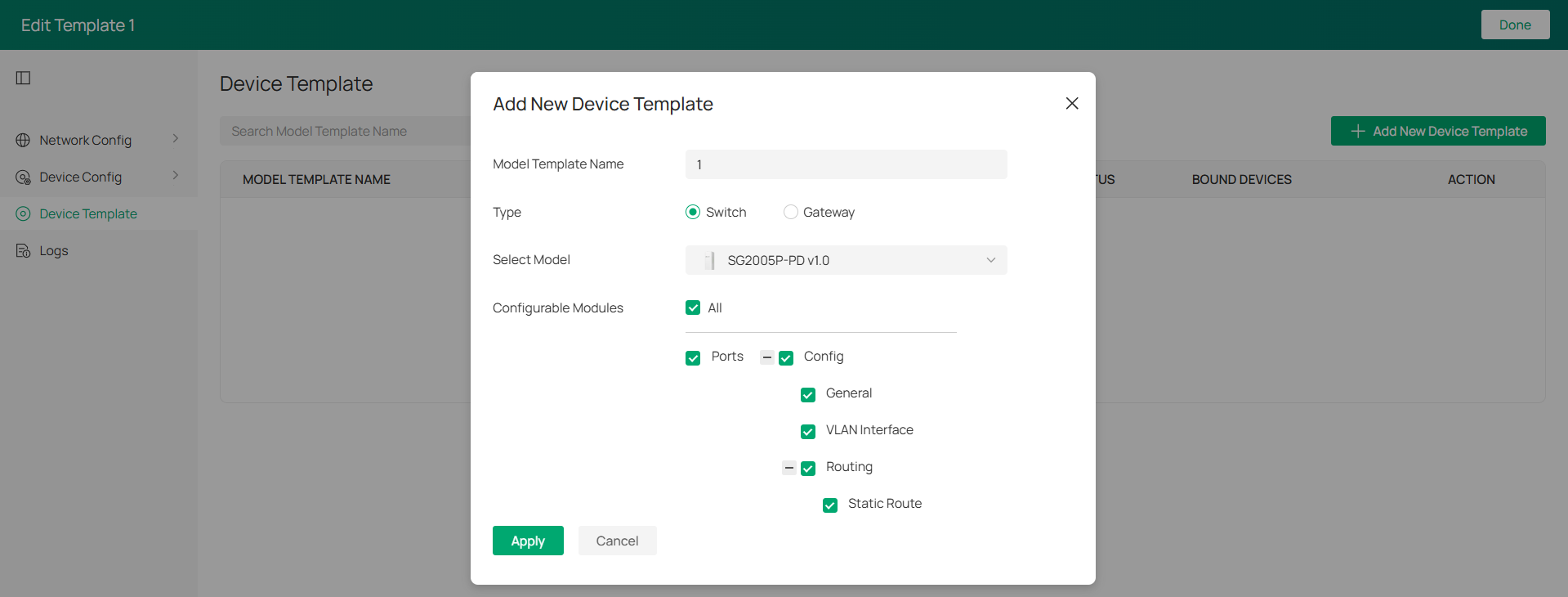
6. Save the settings to go back to the template list.
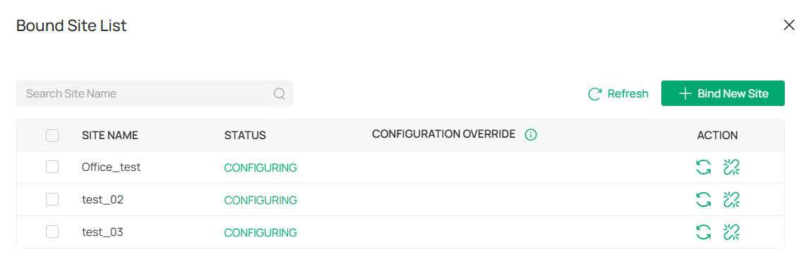
7. Click the Bound Site List icon in the Action column of the template, and click Bind New Site to bind the template to your desired sites. The template's configuration will be synchronized to the bound sites.
In the Action column of a site, you can also click the Re-Apply icon to re-apply template settings or click the Unbind icon to unbind the template from the site.

For more configuration instructions about the site template and device template, refer to https://www.omadanetworks.com/support/faq/4341.
Adopt Devices
Overview
After you create a site, add your devices to the site by making the controller adopt them. Make sure that your devices in each LAN are added to the corresponding site so that they can be managed centrally.

For Software Controller / Hardware Controller
To adopt the devices on the controller, follow these steps:
1) Prepare for communication between the controller and devices.
2) Prepare for device discovery.
3) Adopt the devices.
Step 1: Prepare for Communication
Note:
If the controller and devices are in the same LAN, subnet and VLAN, skip this step.
Make sure that the controller can communicate with the devices. Otherwise, the controller cannot discover or adopt the devices by any means. If the controller and devices are in different LANs, subnets or VLANs, use the following techniques to build up the connection according to your scenario.
1. Set up the network
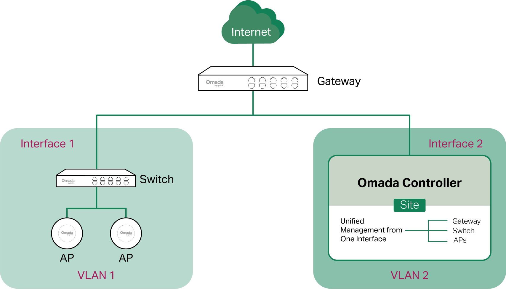
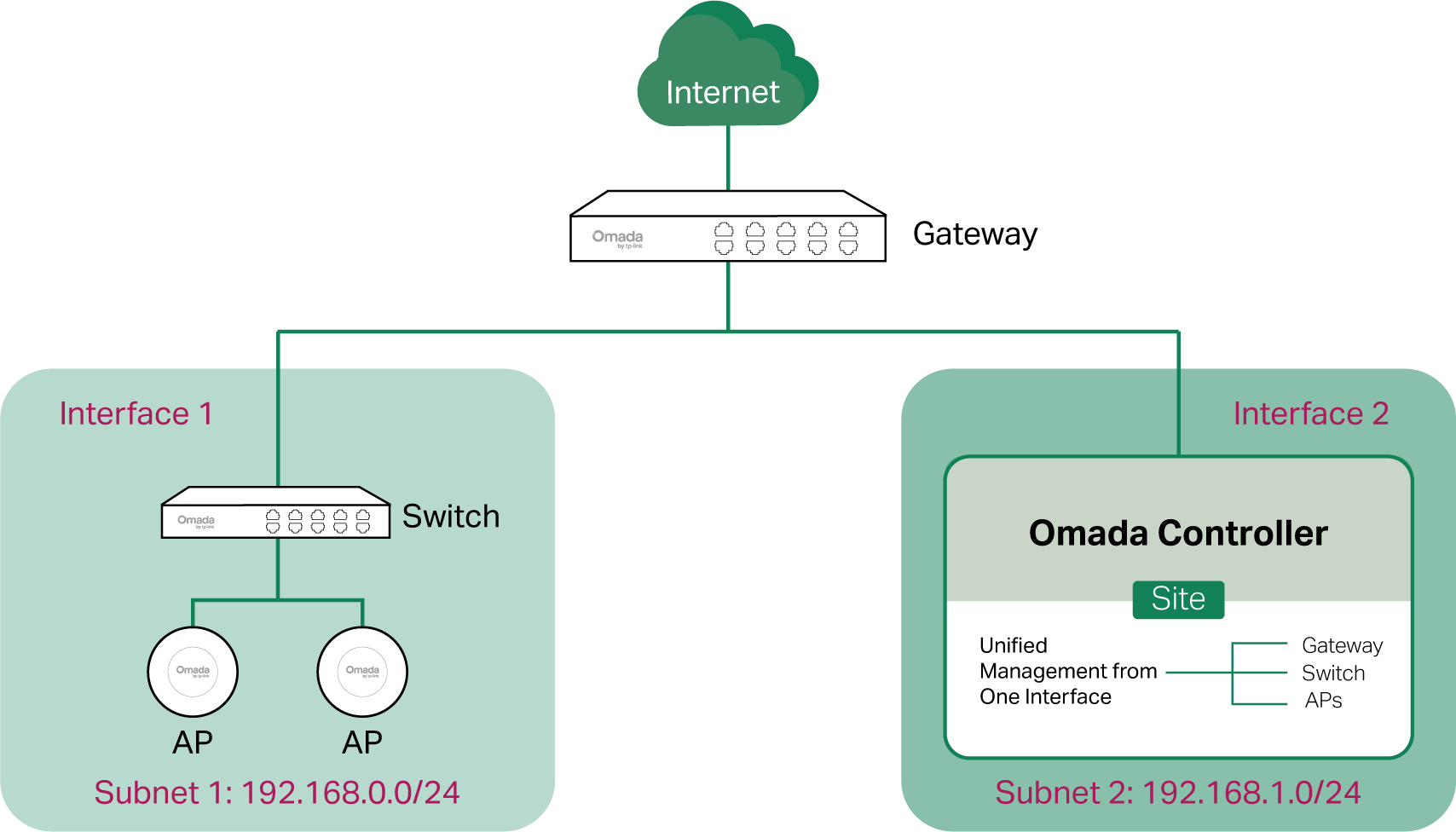
■ Scenario 1: Across VLANs or Subnets
If the controller and devices are in different VLANs or subnets, you need to set up a layer 3 interface for each VLAN or subnet, and make sure the interfaces can communicate with each other.


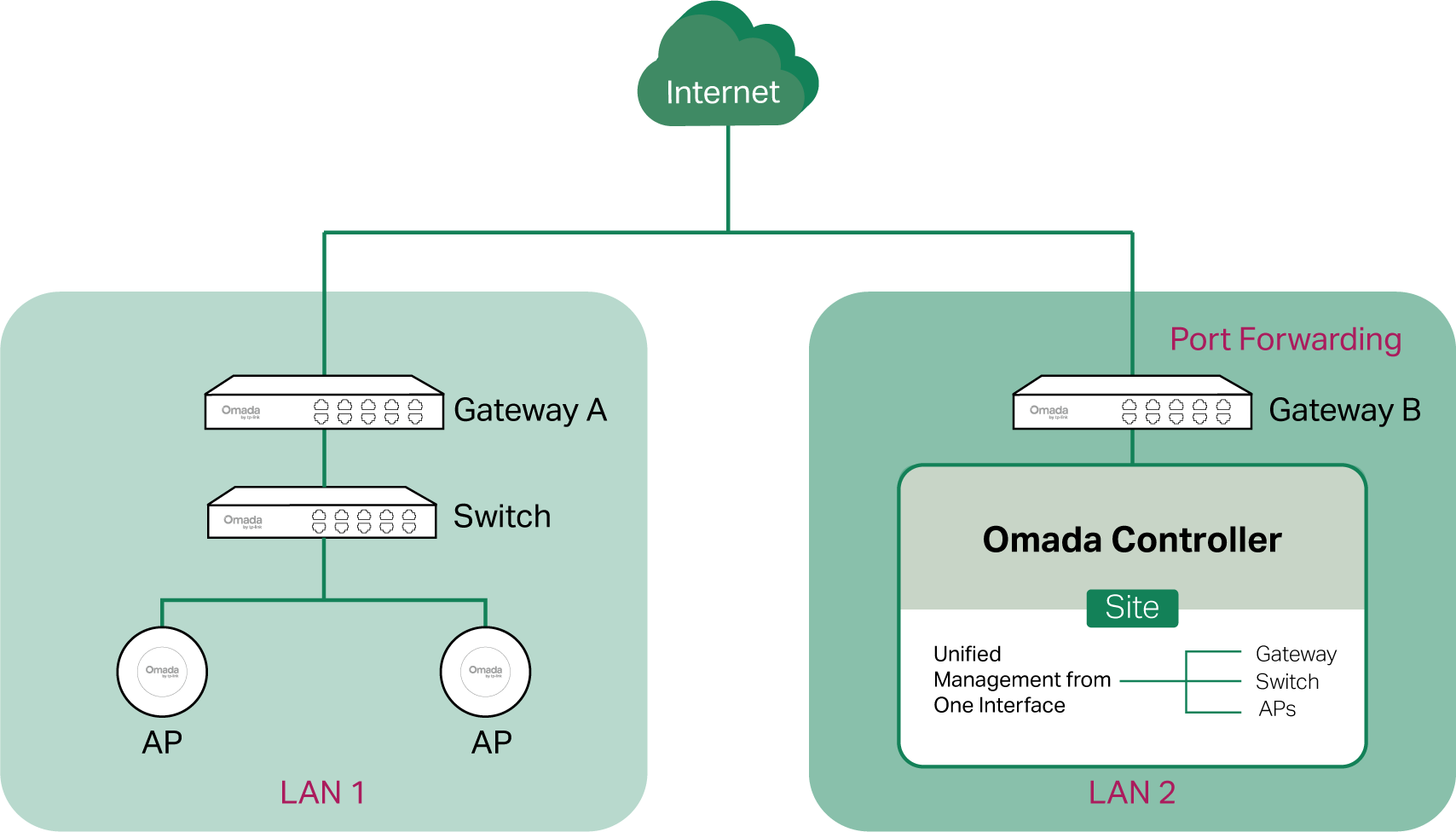
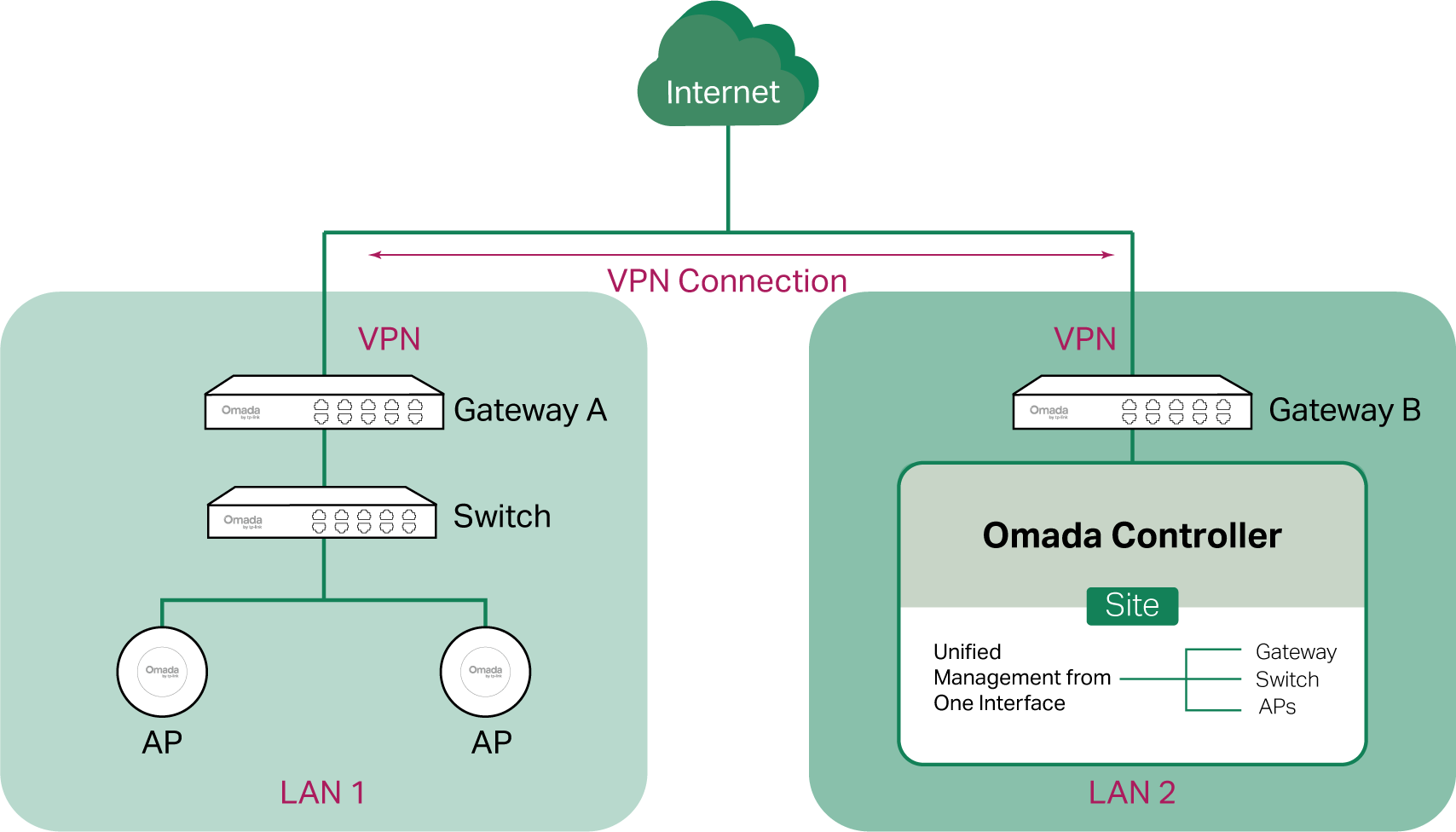
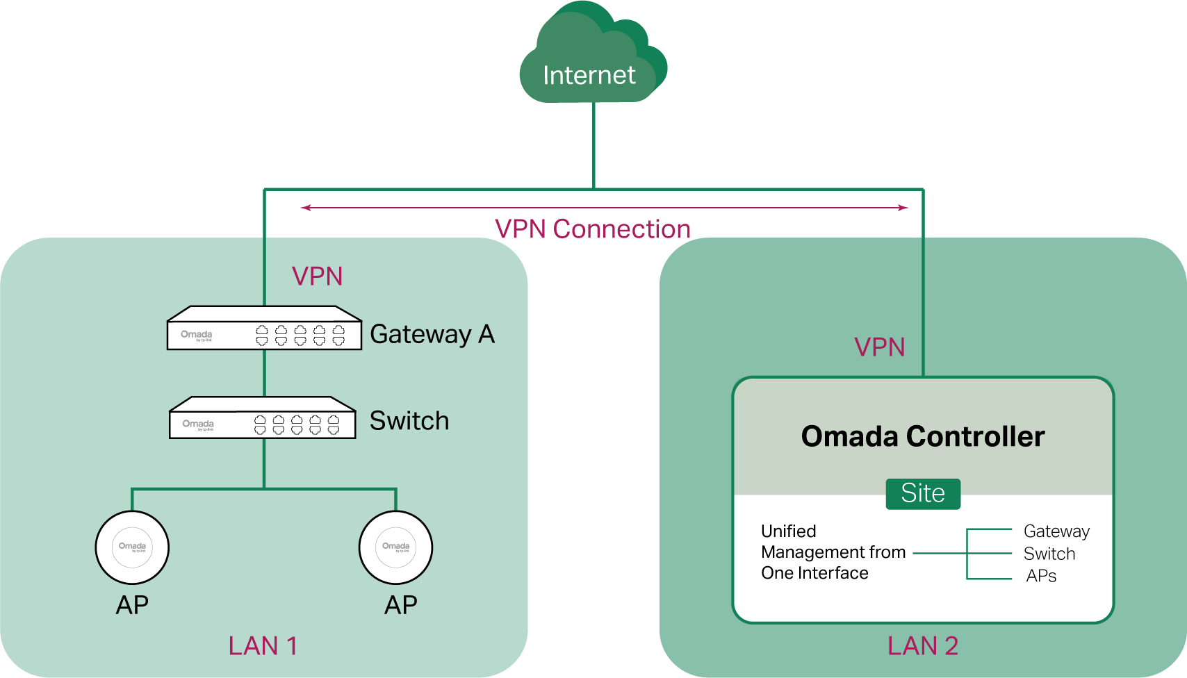
■ Scenario 2: Across LANs
If the controller and devices are in different LANs, you need to establish communication across the internet and the gateways.
By default, devices in LAN 1 cannot communicate with the controller in LAN 2, because Gateway B is in front of the controller and block access to it. To make the controller accessible to the devices, you can use Port Forwarding or VPN.
• Use Port Forwarding
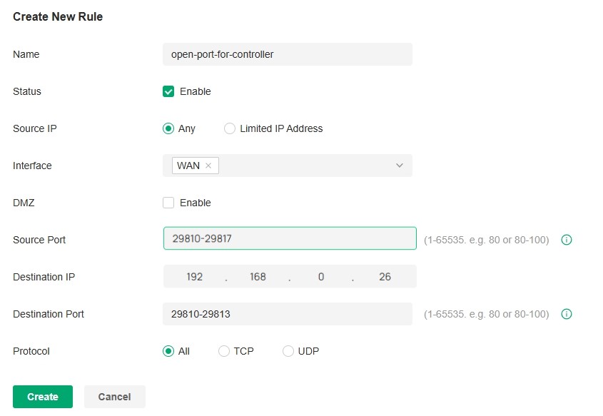
Configure Port Forwarding on Gateway B and open port 29810-29817 for the controller, which are essential for discovering and adopting devices. If you are using firewalls in the networks, make sure that the firewalls don’t block those ports.

To configure Port Forwarding on Gateway B, you need first adopt Gateway B to a site on the controller. Then access the site and go to Network Config > Transmission > NAT > Port Forwarding. Click Create New Rule to load the following page. Specify a name to identify the Port Forwarding rule, check Enable for Status, select Any as Source IP, select the desired WAN port as Interface, disable DMZ, specify 29810-29817 as Source Port and Destination Port, specify the controller’s IP address as Destination IP, and select All as Protocol. Then click Create.

• Use VPN
Set up a VPN connection between Gateway A and Gateway B in Standalone Mode. For details about VPN configuration, refer to the User Guide of the gateways.

2. (Optional) Test the network
If you are not sure whether the controller and devices can establish communication, it’s recommended to do the ping test from the devices to the controller.
Let’s take a switch for example. Log into the web page of the switch in Standalone Mode. Then Go to MAINTENANCE > Network Diagnostics > Ping to load the following page, and specify Destination IP as the IP address of the controller (if you have configured Port Forwarding on the controller side, use the public WAN IP address of the gateway instead). Then click Ping.
Note:
To ping the gateway, turn off Block WAN Ping on the Settings > Network Security > Attack Defense page.

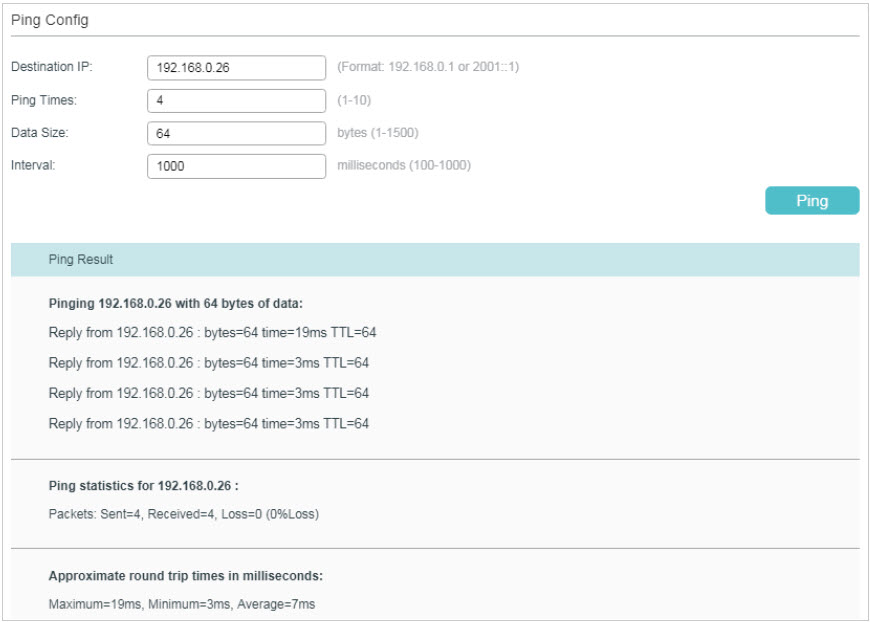
If the ping result shows the packets are received, it implies that the controller can communicate with the devices. Otherwise, the controller cannot communicate with the devices, then you need to check your network.
Step 2: Prepare for Device Discovery
Note:
If the controller and devices are in the same LAN, subnet and VLAN, skip this step. In this scenario, the controller can discover the devices directly, and no additional settings are required.
Make sure that the controller can discover the devices.
When the controller and devices are in different LANs, subnets or VLANs, the controller cannot discover the devices directly. You need to choose Controller Inform URL, Discovery Utility, or DHCP Option 138 as the method to help the controller discover the devices.
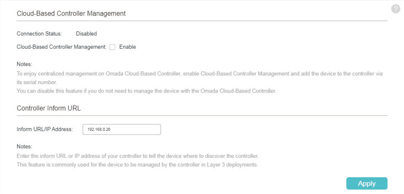
Controller Inform URL informs the devices of the controller’s URL or IP address. Then the devices make contact with the controller so that the controller can discover the devices.
You can configure Controller Inform URL for devices in Standalone Mode. Let’s take a switch for example. Log into the management page of the switch in Standalone Mode and go to SYSTEM > Controller Settings to load the following page. In Controller Inform URL, specify Inform URL/IP Address as the controller’s URL or IP address (if you have configured Port Forwarding on the controller side, use the public WAN IP address of the gateway instead). Then click Apply.

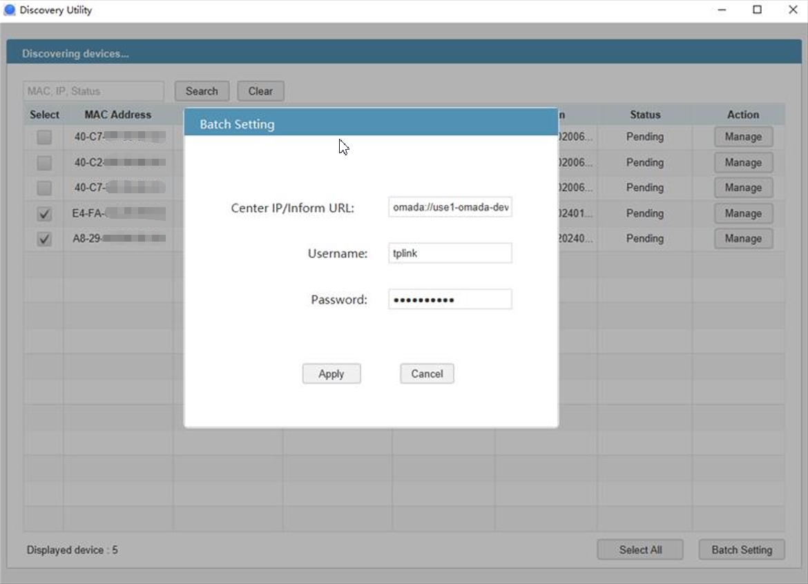
Discovery Utility can discover the devices in the same LAN, subnet and VLAN, and inform the devices of the controller’s IP address. Then the devices make contact with the controller so that the controller can discover the devices.
1. Download Discovery Utility from https://support.omadanetworks.com/product/omada-software-controller/?resourceType=download and then install it on your PC which should be located in the same LAN, subnet and VLAN as your devices.
2. Open Discovery Utility and you can see a list of devices. Select the devices to be adopted and click Batch Setting.

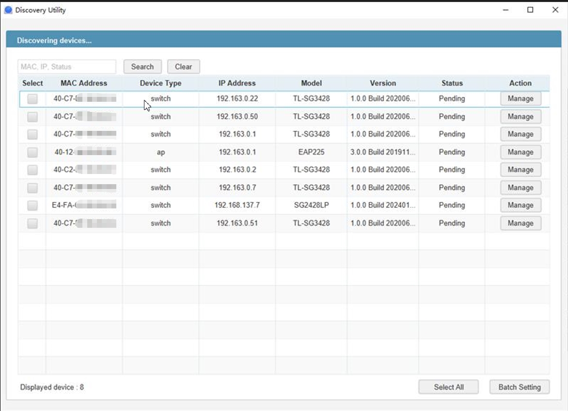
3. Specify Controller Hostname/IP as the IP address of the controller (if you have configured Port Forwarding on the controller side, use the public WAN IP address of the gateway instead), and enter the username and password of the devices. By default, the username and password are both admin. Then click Apply. Wait until the setting succeeds.

DHCP Option 138 informs a DHCP client, such as a switch or an EAP, of the controller’s IP address when the DHCP client sends DHCP requests to the DHCP server, which is typically a gateway.
1. To use DHCP Option 138, you need to adopt the gateway on the controller first, which may require other techniques like Controller Inform URL or Discovery Utility if necessary.
2. After the gateway is adopted, access the site and go to Network Config > Network Settings > LAN.
3. Choose the LAN where the DHCP clients are located and click the Edit icon in the upper right.
4. Enable DHCP Server and configure common DHCP parameters. Then click Advanced DHCP Options and specify Option 138 as the controller’s IP address (if you have configured Port Forwarding on the controller side, use the public WAN IP address of the gateway instead).
5. Configure other parameters and save the settings.

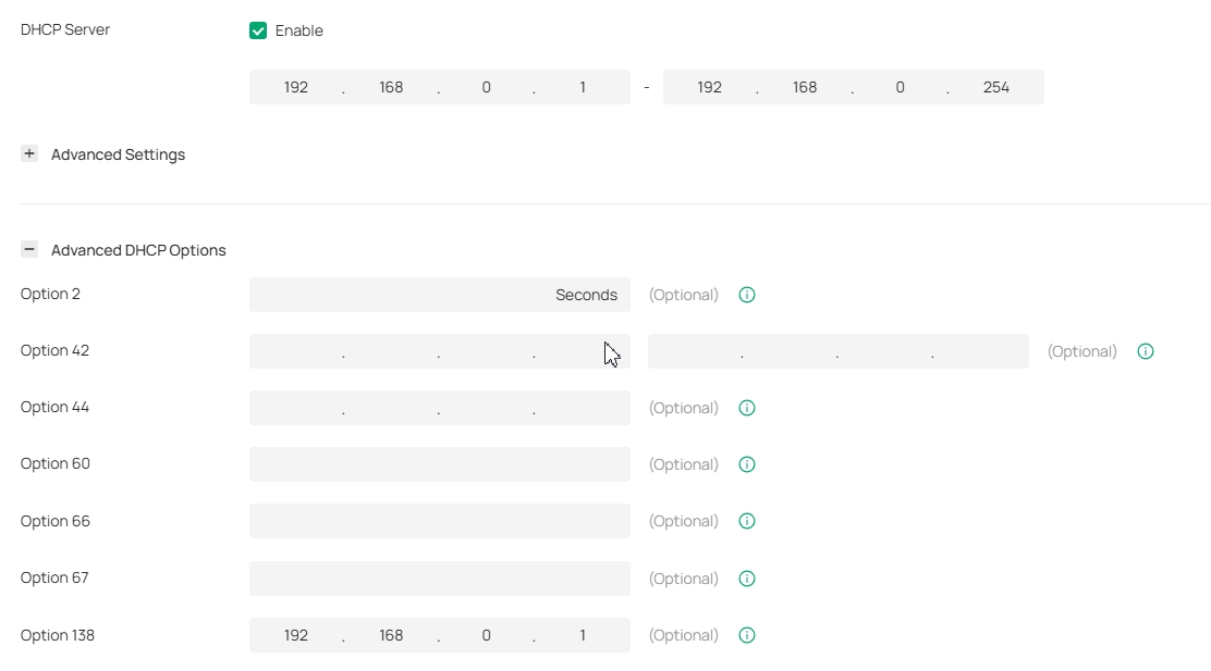
6. To make DHCP Option 138 take effect, you need to renew DHCP parameters for the DHCP clients. One possible way is to disconnect the DHCP clients and then reconnect them.
Step 3: Adopt the Devices
1. Launch the controller and access a site.
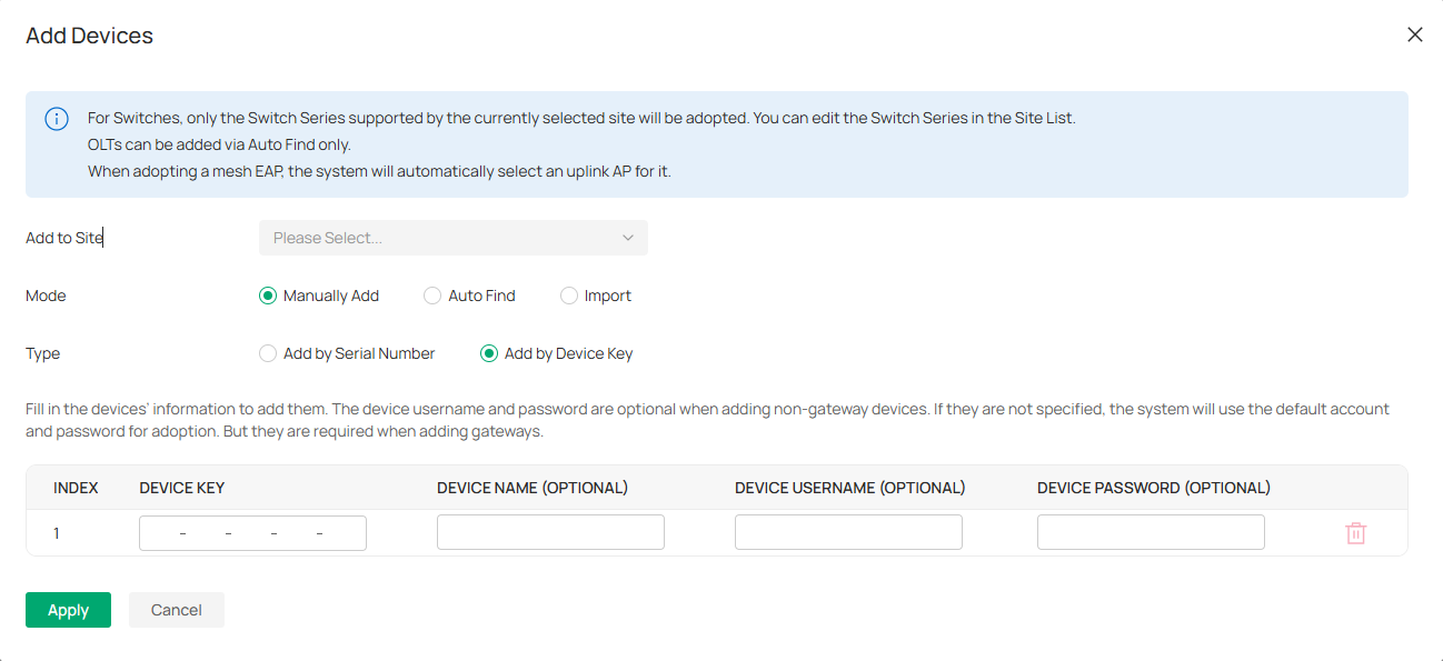
2. Go to Devices and click Add Devices. Choose a method to add your devices.

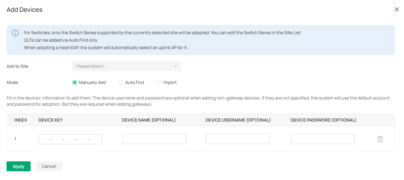
• Manually Add
Fill in the devices’ information to add them. The device username and password are optional when adding non-gateway devices. If they are not specified, the system will use the default account and password for adoption. But they are required when adding gateways.
• Auto Find
Automatically find the Omada devices with Inform URL configured to add them.
• Import
Download the template and fill in your devices’ information. Then import the file. Up to 1500 devices can be imported at a time.
3. Once the devices are adopted, they are subject to central management in the site.
For Integrated Gateway (Controller)
The integrated gateway has been adopted by the build-in Controller by default during the initial setup.
To adopt other devices on the build-in controller of the Integrated Gateway, follow these steps:
1) Prepare for communication between the controller and devices.
2) Prepare for device discovery.
3) Adopt the devices.
Step 1: Prepare for Communication
Note:
If the controller and devices are in the same LAN, subnet and VLAN, skip this step.
Make sure that the controller can communicate with the devices. Otherwise, the controller cannot discover or adopt the devices by any means. If the controller and devices are in different LANs, subnets or VLANs, use the following techniques to build up the connection according to your scenario.
1. Set up the network.
■ Scenario 1: Across VLANs or Subnets
If the controller and devices are in different VLANs or subnets. You need to set up a layer 3 interface for each VLAN or subnet, and make sure the interfaces can communicate with each other.
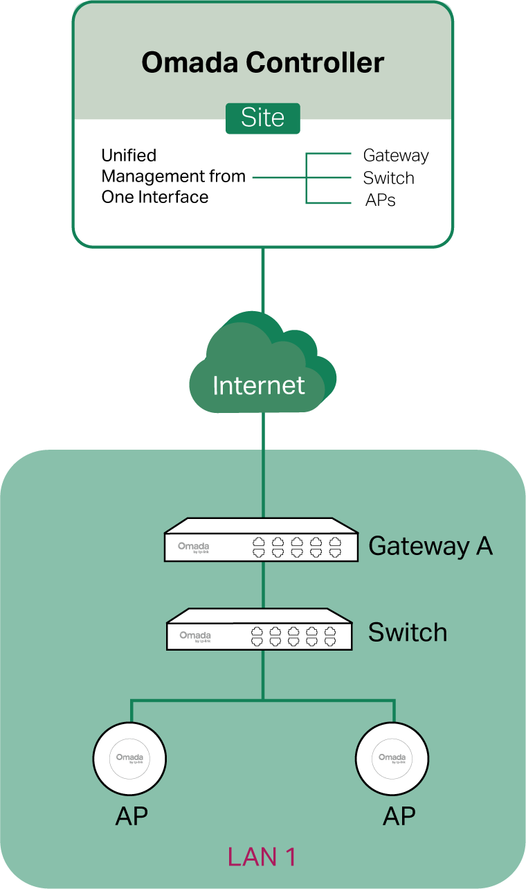
■ Scenario 2: Across LANs
As shown in the following figure, the controller and devices are in different LANs. You need to establish communication across the internet and the gateways.
By default, devices in LAN 1 cannot communicate with the controller in LAN 2, because Gateway A blocks their access to the controller. To make the controller accessible to the devices, you can use Port Forwarding or VPN.
• Use Port Forwarding
Configure Port Forwarding and open port 29810-29817 for the controller, which are essential for discovering and adopting devices. If you are using firewalls in the networks, make sure that the firewalls don’t block those ports.

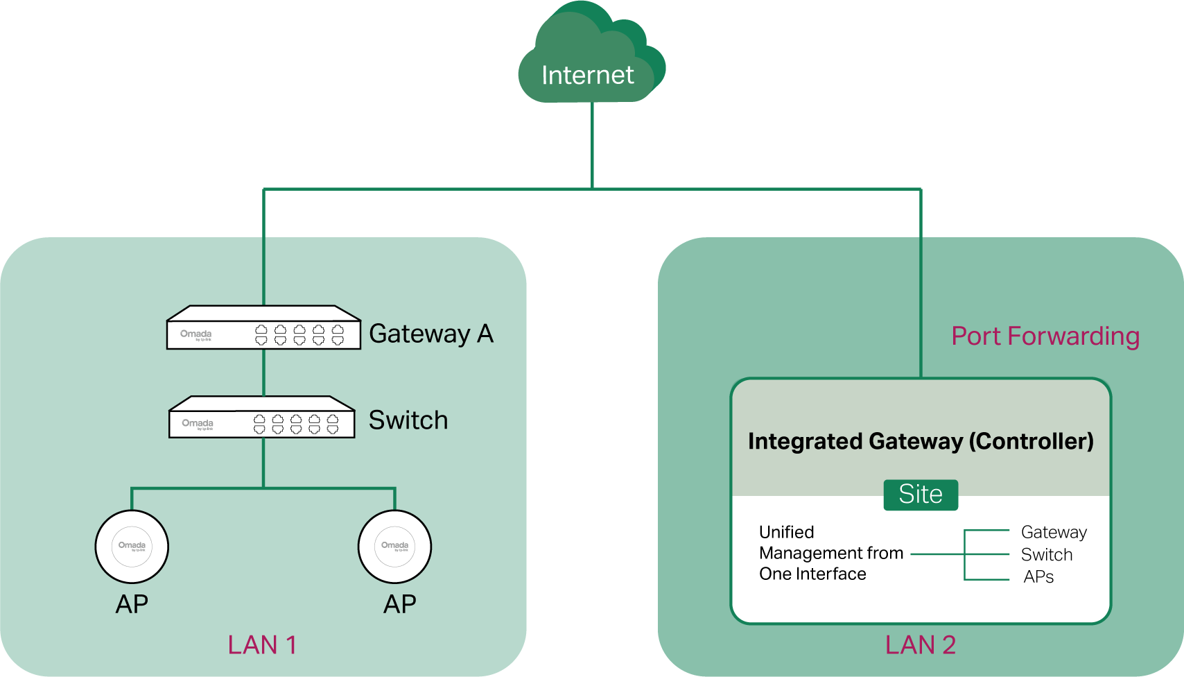
To configure Port Forwarding on the controller, go to Network Config > Transmission > NAT > Port Forwarding. Click Create New Rule to load the following page. Specify a name to identify the Port Forwarding rule, check Enable for Status, select Any as Source IP, select the desired WAN port as Interface, disable DMZ, specify 29810-29817 as Source Port and Destination Port, specify the controller’s IP address as Destination IP, and select All as Protocol. Then click Create.
• Use VPN
Set up a VPN connection between Gateway A and the controller. For details about VPN configuration, refer to the corresponding chapter of this guide.

2. (Optional) Test the network.
If you are not sure whether the controller and devices can establish communication, it’s recommended to do the ping test from the devices to the controller.
Let’s take a switch for example. Log into the web page of the switch in Standalone Mode. Then Go to MAINTENANCE > Network Diagnostics > Ping to load the following page, and specify Destination IP as the IP address of the controller (if you have configured Port Forwarding on the controller side, use the public WAN IP address of the gateway instead). Then click Ping.
Note:
To ping the gateway, turn off Block WAN Ping on the Settings > Network Security > Attack Defense page.
If the ping result shows the packets are received, it implies that the controller can communicate with the devices. Otherwise, the controller cannot communicate with the devices, then you need to check your network.
Step 2: Prepare for Device Discovery
Note:
If the controller and devices are in the same LAN, subnet and VLAN, skip this step. In this scenario, the controller can discover the devices directly, and no additional settings are required.
Make sure that the controller can discover the devices.
When the controller and devices are in different LANs, subnets or VLANs, the controller cannot discover the devices directly. You need to choose Controller Inform URL, Discovery Utility, or DHCP Option 138 as the method to help the controller discover the devices.
Controller Inform URL informs the devices of the controller’s URL or IP address. Then the devices make contact with the controller so that the controller can discover the devices.
You can configure Controller Inform URL for devices in Standalone Mode. Let’s take a switch for example. Log into the management page of the switch in Standalone Mode and go to SYSTEM > Controller Settings to load the following page. In Controller Inform URL, specify Inform URL/IP Address as the controller’s URL or IP address (if you have configured Port Forwarding on the controller side, use the public WAN IP address of the gateway instead). Then click Apply.
Discovery Utility can discover the devices in the same LAN, subnet and VLAN, and inform the devices of the controller’s IP address. Then the devices make contact with the controller so that the controller can discover the devices.
1. Download Discovery Utility from https://support.omadanetworks.com/product/omada-software-controller/?resourceType=download and then install it on your PC which should be located in the same LAN, subnet and VLAN as your devices.
2. Open Discovery Utility and you can see a list of devices. Select the devices to be adopted and click Batch Setting.
3. Specify Controller Hostname/IP as the IP address of the controller (if you have configured Port Forwarding on the controller side, use the public WAN IP address of the gateway instead), and enter the username and password of the devices. By default, the username and password are both admin. Then click Apply. Wait until the setting succeeds.
 ■
■ DHCP Option 138 informs a DHCP client, such as a switch or an EAP, of the controller’s IP address when the DHCP client sends DHCP requests to the DHCP server, which is typically a gateway.
1. To use DHCP Option 138, you need to adopt the gateway on the controller first, which may require other techniques like Controller Inform URL or Discovery Utility if necessary.
2. After the gateway is adopted, access the site and go to Network Config > Network Settings > LAN.
3. Choose the LAN where the DHCP clients are located and click the Edit icon in the upper right.
4. Enable DHCP Server and configure common DHCP parameters. Then click Advanced DHCP Options and specify Option 138 as the controller’s IP address (if you have configured Port Forwarding on the controller side, use the public WAN IP address of the gateway instead).
5. Configure other parameters and save the settings.
6. To make DHCP Option 138 take effect, you need to renew DHCP parameters for the DHCP clients. One possible way is to disconnect the DHCP clients and then reconnect them.
Step 3: Adopt the Devices
1. Launch the controller and access a site.
2. Go to Devices and click Add Devices. Choose a method to add your devices.
• Manually Add
Fill in the devices’ information to add them. The device username and password are optional when adding non-gateway devices. If they are not specified, the system will use the default account and password for adoption. But they are required when adding gateways.
• Auto Find
Automatically find the Omada devices with Inform URL configured to add them.
• Import
Download the template and fill in your devices’ information. Then import the file. Up to 1500 devices can be imported at a time.
3. Once the devices are adopted, they are subject to central management in the site.
For Cloud-Based Controller
To adopt the devices on the controller, follow these steps:
1) Connect to the internet.
2) Prepare for controller management.
3) Adopt the devices.
Step 1: Connect to the Internet
1. Set up the network.
Make sure that your devices are connected to the internet.

If you are using firewalls in your network, make sure that the firewall doesn’t block traffic from the controller. To configure your firewall policy, you may want to know the URL of the controller. After you open the web page of the controller, you can get the URL from the address bar of the browser.
2. (Optional) Test the network.
If you are not sure whether the devices are connected to the internet, it’s recommended to do the ping test from the devices to a public IP address, such as 8.8.8.8.
Let’s take a switch for example. Log into the web page of the switch in Standalone Mode. Go to MAINTENANCE > Network Diagnostics > Ping to load the following page. Specify Destination IP as a public IP address, such as 8.8.8.8. Then click Ping.

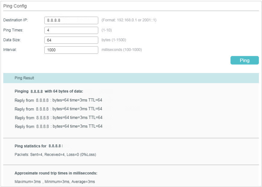
If the ping result shows the packets are received, it implies that the devices are connected to the internet. Otherwise, the devices are not connected to the internet, then you need to check your network.
Step 2: Prepare for Controller Management
Note:
If your devices are on the factory default setting, skip this step.
The Cloud-Based Controller Management feature allows the devices to be adopted by the Cloud-Based Controller. Make sure Cloud-Based Controller Management is enabled on the devices. For details, refer to the User Guide of your devices, which can be downloaded from https://support.omadanetworks.com/product/.
Let’s take a switch for example. Log into the web page of the switch in Standalone Mode. Go to SYSTEM > Controller Settings to load the following page. In Cloud-Based Controller Management, enable Cloud-Based Controller Management and click Apply.
 Step 3: Adopt the Devices
1. Ensure your devices are compatible with your Cloud-Based Controller.
• Omada Central Essentials:
https://www.omadanetworks.com/omada-cloud-essentials/product-list/
• Omada Central Standard:
https://www.omadanetworks.com/omada-cloud-based-controller/product-list/
2.Launch an Omada Central organization, go to Omada Network, and access a site.
3.Go to Devices and click Add Devices. Choose a method to add your devices.

• Manually Add
Fill in the devices’ information to add them. The device username and password are optional when adding non-gateway devices. If they are not specified, the system will use the default account and password for adoption. But they are required when adding gateways.
• Auto Find
Automatically find the Omada devices with Inform URL configured to add them.
• Import
Download the template and fill in your devices’ information. Then import the file. Up to 1500 devices can be imported at a time.
4. Once the devices are adopted, they are subject to central management in the site.
Configuring Controller Settings
Controller settings control the appearance and behavior of the controller and provide methods of data backup, restoration, migration, and more.
System Settings
Launch the controller and access the Global View. Go to Settings > System Settings.
Controller Status
In Controller Status, you can view the controller-related information and status.
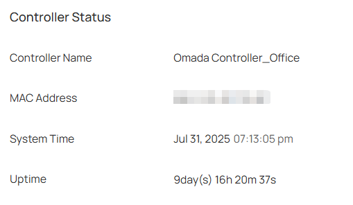
|
Controller Name |
Displays the controller name, which identifies the controller. You can specify the controller name in Controller Settings. |
|---|---|
|
MAC Address |
Displays the MAC address of the controller. |
|
System Time |
Displays the system time of the controller. The system time is based on the time zone which you configure in Controller Settings. |
|
Uptime |
Displays how long the controller has been working. |
Controller Updates
In Controller Updates, you can view the controller version information and check for updates.
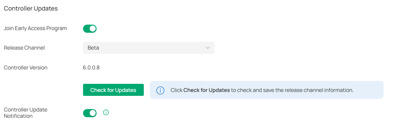
|
Join Early Access Program |
Enable the option to join the program and check for firmware in the Release Channel > Beta for upgrading, so you can try out in-development features and help improve them. |
|---|---|
|
Release Channel |
Select the Release Channel of the controller to check whether the corresponding Channel has a newer version. |
|
Controller Version |
Display the software version of the controller. |
|
Check for Updates |
Click to check for any updates of the controller. |
|
Controller Update Notification |
Enable the option and the system will query the cloud for controller firmware updates. |
HTTPS Certificate
If you have assigned a domain name to the controller for login, to eliminate the “untrusted certificate” error message in the login process, import the corresponding SSL certificate and private key issued by the certificate authority in HTTPS Certificate.
Note:
• HTTPS Certificate configuration is only available for the Software Controller and Hardware Controller.
• You need to restart you controller for the imported SSL certificate to take effect.
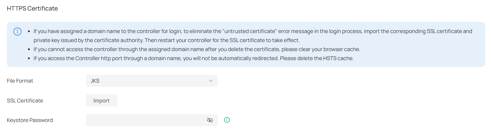
|
File Format |
Select the format of your certificate, and import the certificate file. |
|---|---|
|
SSL Certificate |
Import the SSL certificate to create an encrypted link between the controller and server. JKS: Import your SSL certificate and enter the Keystore Password if your SSL certificate has the password. Otherwise, leave it blank. PFX: Import your SSL certificate and enter the Private Key Password if your SSL certificate has the password. Otherwise, leave it blank. PEM: Import your SSL certificate and SSL Key. |
Note:
For the PEM-formatted certificate:
• Starts with: -----BEGIN CERTIFICATE-----
• Ends with: -----END CERTIFICATE-----
• Certificate chain is supported and no blank line is allowed between two certificate chains.
For the PEM-formatted key:
• RSA encryption is required.
• Starts with: -----BEGIN RSA PRIVATE KEY-----
• Ends with: -----END RSA PRIVATE KEY -----
• The key can be placed behind certificate file, and they can be imported together.
System Logging
In System Logging, you can customize the log level if needed.
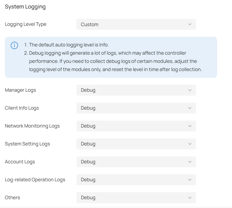
|
Logging Level Type |
Choose whether to customize the log level. |
|---|---|
|
Manager Logs |
Select the log level of the manager module, which mainly includes device management and site-related configurations. |
|
Client Info Logs |
Select the log level of the client info module, which mainly includes functions related to client monitoring. |
|
Network Monitoring Logs |
Select the log level of the network monitoring module, which mainly includes functions related to data monitoring. |
|
System Setting Logs |
Select the log level of the system setting module, which mainly includes system data related functions. |
|
Account Logs |
Select the log level of the account module, which mainly includes account-related functions. |
|
Log-related Operation Logs |
Select the log level of the log-related operation module, which mainly includes related functions of the log page. |
|
Others |
Select the log level of other modules. |
Access Config
In Access Config, you can specify the port used by the controller for management and portal.
Note:
• Access Config is only available on the on-premises controller.
• Once applying the change of HTTPS and HTTP port, restart the controller to make the change effective.
• For security, the HTTPS and HTTP port for Potal should be different from that for controller management.

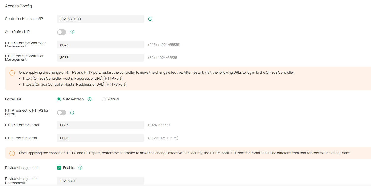
|
Controller Hostname/IP |
Enter the hostname or IP address of the controller which will be used as the Controller URL in the notification email for resetting your controller password. You can keep it default and IP address recognized by the controller will be used as the Controller URL. |
|---|---|
|
Auto Refresh IP |
(Only for hardware controller) Enable the feature and the hardware controller will refresh its IP address automatically. |
|
HTTPS Port for Controller Management |
Specify the HTTPS port used by the controller for management. After setting the port, you can visit https://[Controller Host’s IP address or URL]:[HTTPS Port] to log in to the Controller. |
|
HTTP Port for Controller Management |
Specify the HTTP port used by the controller for management. After setting the port, you can visit https://[Controller Host’s IP address or URL]:[HTTP Port] to log in to the Controller. |
|
Portal URL |
Set the Portal URL. Auto Refresh: The device will automatically use the actual IP address of the Controller as the portal redirection destination. Manual: Manually enter a domain name or IP address that clients can access. |
|
HTTP redirect to HTTPS for Portal |
If enabled, clients will be redirected to Captive Portal using HTTPS instead of HTTP. |
|
HTTPS Port for Portal |
Specify the HTTPS port used by the controller for Portal. |
|
HTTP Port for Portal |
Specify the HTTP port used by the controller for Portal. |
|
Device Management |
When enabled, the controller will apply the Device Management Hostname/IP you specified to managed devices for remote management. |
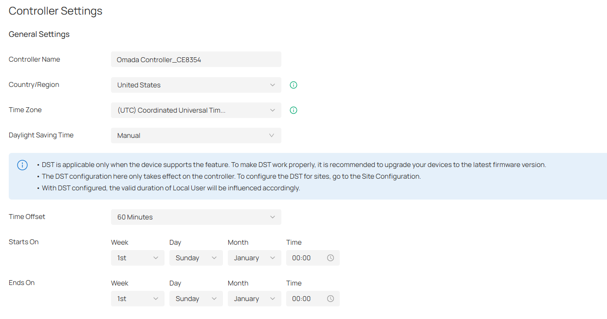
Controller Settings
Launch the controller and access the Global View. Go to Settings > Controller Settings (for an on-premises controller) or Settings > Organization Settings (for a Cloud-Based Controller).
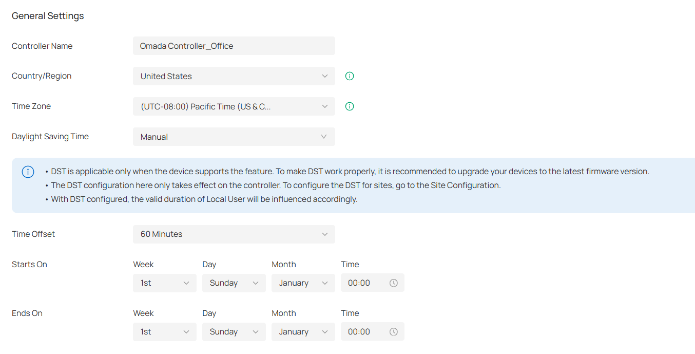
General Settings
In General Settings, you can configure general settings of the controller.
■ For Hardware Controller and Integrated Gateway (Controller)
Note:
The Country/Region, Time Zone, and Daylight Saving Time settings are the same as those of the default site.
|
Controller Name |
Specify the Controller Name to identify the controller. |
|---|---|
|
Country/Region |
Select the location of the controller. The configuration here only takes effect on the controller. To configure the Country/Region for sites, go to the Site Configuration. |
|
Time Zone |
Select the Time Zone of the controller according to your region. For controller settings and statistics, time is displayed based on the Time Zone. The configuration here only takes effect on the controller. To configure the Time Zone for sites, go to the Site Configuration. |
|
Daylight Saving Time |
Enable the feature if your country/region implements DST (Daylight Saving Time). |
|
Time Offset |
Select the time added in minutes when Daylight Saving Time starts. |
|
Starts On |
Specify the time when the DST starts. The clock will be set forward by the time offset you specify. |
|
Ends On |
Specify the time when the DST ends.The clock will be set back by the time offset you specify. |
■ For Software Controller / Cloud-Based Controller
|
Controller Name |
Specify the Controller Name to identify the controller. |
|---|---|
|
Country/Region |
Select the location of the controller. The configuration here only takes effect on the controller. To configure the Country/Region for sites, go to the Site Configuration. |
|
Time Zone |
Select the Time Zone of the controller according to your region. For controller settings and statistics, time is displayed based on the Time Zone. The configuration here only takes effect on the controller. To configure the Time Zone for sites, go to the Site Configuration. |
|
Daylight Saving Time |
Enable the feature if your country/region implements DST (Daylight Saving Time). |
|
Time Offset |
Select the time added in minutes when Daylight Saving Time starts. |
|
Starts On |
Specify the time when the DST starts. The clock will be set forward by the time offset you specify. |
|
Ends On |
Specify the time when the DST ends.The clock will be set back by the time offset you specify. |
Services
In Services, you can configure remote logging and client idle threshold.
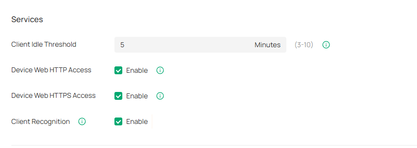
|
Client Idle Threshold |
The controller will consider a client offline (thus disconnect it) when it is idle for longer than the specified threshold. If the specified threshold is too short, clients may be disconnected frequently. |
|---|---|
|
Device Web HTTP Access |
This function controls HTTP access to the web pages of managed Omada devices. If it is turned off, HTTP access to the devices’ web pages will be unavailable. |
|
Device Web HTTPS Access |
This function controls HTTPS access to the web pages of managed Omada devices. If it is turned off, HTTPS access to the devices’ web pages will be unavailable. |
|
Client Recognition |
With the feature enabled, network devices will report client information in real time to ensure the accuracy of client identification. |
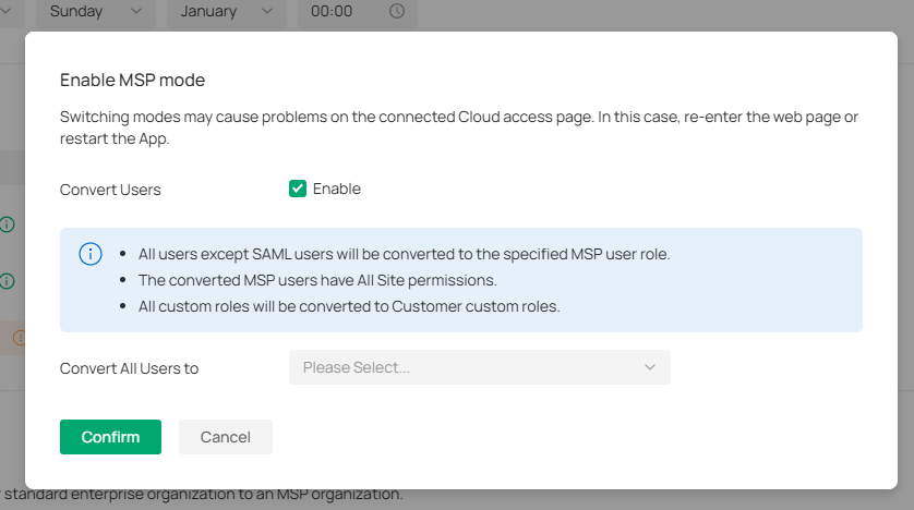
MSP Mode
In MSP Mode, you can convert your standard enterprise organization to an MSP organization. For more settings in MSP mode, refer to Managing Customer Networks in MSP Mode.
|
Convert Users |
When enabled, all users except SAML users will be converted to the specified MSP user role. The converted MSP users have All Site permissions. All custom roles will be converted to Customer custom roles. |
|---|---|
|
Convert All Users to |
Select to convert all users to MSP Admin or MSP Viewer. |
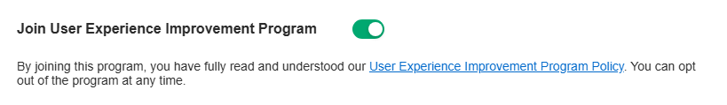
Join User Experience Improvement Program
You can participate in the user experience improvement program and help improve the quality and performance of TP-Link products by sending statistics and usage information.
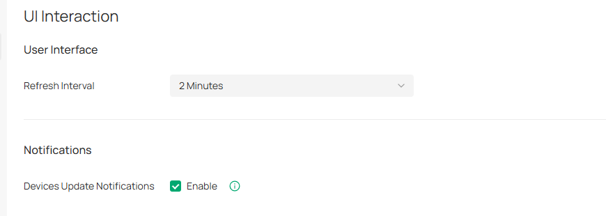
UI Interaction
In UI Interaction, you can customize the UI interaction settings of the controller according to your preferences.
Launch the controller and access the Global View. Go to Settings > UI Interaction.
|
Refresh Interval |
Specify the interval to automatically refresh the UI interface. |
|---|---|
|
Devices Update Notification |
With this feature enabled, you will receive an update notification when a new firmware version for your device is available. |
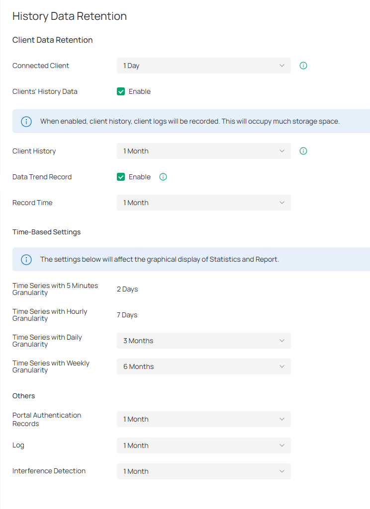
History Data Retention
In History Data Retention, you can specify how the controller retains its data.
Launch the controller and access the Global View. Go to Settings > History Data Retention.
|
Connected Client |
Record connected clients according to the time you specified. When the limit is exceeded, the oldest disconnected known client may be deleted. |
|---|---|
|
Clients’ History Data |
When enabled, client history and client logs will be recorded. This will occupy much storage space. |
|
Client History |
Specify the retention time of client online and offline records. |
|
Data Trend Record |
When enabled, client trend statistics and charts will be retained, which will take up lots of storage space. |
|
Time Series with 5 Minutes Granularity |
Displays the retention time of AP, switch, gateway, and client data. Corresponding to 5-minute statistics. |
|
Time Series with Hourly Granularity |
Displays the retention time of AP, switch, gateway, and client data. Corresponding to hourly statistics. |
|
Time Series with Daily Granularity |
Specify the retention time of AP, switch, gateway, and client data. Corresponding to daily statistics. |
|
Time Series with Weekly Granularity |
Specify the retention time of client data. Corresponding to weekly statistics. |
|
Portal Authentication Records |
Specify the retention time of portal authorization records. Corresponding to Hotspot - Authorized Clients. |
|
Log |
Specify the retention time of logs. |
|
Interference Detection |
Specify the retention time of scanned Interference Detection. Corresponding to Network Tools-Interference Detection. |
Server Settings
Launch the controller and access the Global View. Go to Settings > Server Settings.
Mail Server
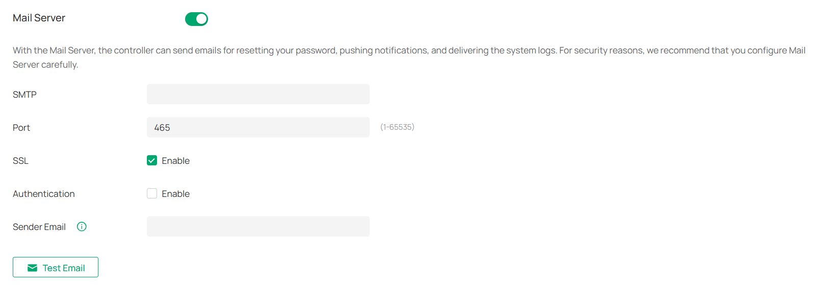
With the Mail Server, the controller can send emails for resetting your password, pushing notifications, and delivering the system logs. The Mail Server feature works with the SMTP (Simple Mail Transfer Protocol) service provided by an email service provider.
Configuration
1. Log in to your email account and enable the SMTP (Simple Mail Transfer Protocol) Service. For details, refer to the instructions of your email service provider.
2. Launch the controller and access the Global View. Go to Settings > Server Settings. Enable Mail Server and configure the parameters. Then apply the settings.
|
SMTP |
Enter the URL or IP address of the SMTP server according to the instructions of the email service provider. |
|---|---|
|
Port |
Configure the port used by the SMTP server according to the instructions of the email service provider. |
|
SSL |
Enable or disable SSL according to the instructions of the email service provider. SSL (Secure Sockets Layer) is used to create an encrypted link between the controller and the SMTP server. |
|
Authentication |
Enable or disable Authentication according to the instructions of the email service provider. If Authentication is enabled, the SMTP server requires the username and password for authentication. |
|
Username |
When Authentication is enabled, enter your email address as the username. |
|
Authorization Code |
When Authentication is enabled, enter the authorization code as the password, which is provided by the email service provider when you enable the SMTP service. |
|
Sender Email |
(Optional) Specify the email address of the sender. If you leave it blank, the controller will use your current email address. |
|
Test Emal |
Test the Mail Server configuration by sending a test email to an email address that you specify. |
Built-in RADIUS
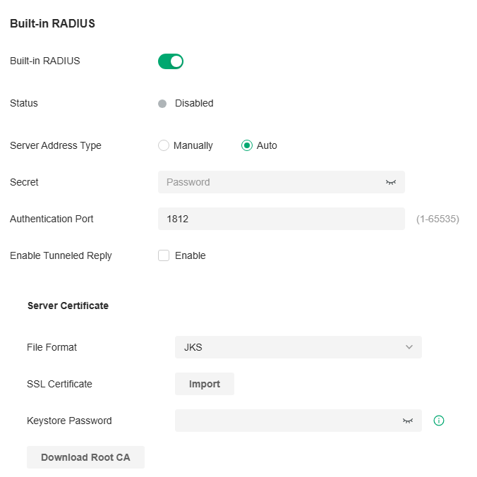
A RADIUS server maintains a database which stores the identity information of legal users. It authenticates users against the database when the users are requesting to access the network, and provides authorization and accounting services for them.
For the on-premises controller, you can set up the built-in RADIUS server for user authentication.
Note:
Built-in RADIUS server is only available for the Software Controller and Hardware Controller. It has been removed from OC200 due to specification restriction.

|
Built-in RADIUS |
Toggle on to enable the built-in RADIUS server. |
|---|---|
|
Status |
Displays the current status of the server. |
|
Server Address Type |
Specify the built-in server address type. When the controller is on a computer with multiple network adapters, and the type is configured as Auto, the server address will be sent to the device according to the ports connected to the device. When the type is configured as Manual, the user needs to manually configure the server's IP address, which should be the address the device can communicate with. |
|
Secret |
Specify the RADIUS server key. |
|
Authentication Port |
Specify the RADIUS server authentication port. |
|
Enable Tunneled Reply |
Enable this option if you want to allow the reply of the Tunneled Reply-related attributes to the device. Only after this option is enabled can the client be assigned a VLAN. |
|
File Format |
Select the format of your certificate, and import the certificate file. |
|
SSL Certificate |
Import the SSL certificate to create an encrypted link between the controller and server. JKS: Import your SSL certificate and enter the Keystore Password if your SSL certificate has the password. Otherwise, leave it blank. PFX: Import your SSL certificate and enter the Private Key Password if your SSL certificate has the password. Otherwise, leave it blank. PEM: Import your SSL certificate and SSL Key. |
|
Download Root CA |
Export the installable built-in authentication server root certificate. If the user uploads a certificate, the root certificate of the uploaded certificate will be exported; otherwise the default root certificate will be exported. The DNS name of the default root certificate is “Omada”. |
Note:
For the PEM-formatted certificate:
• Starts with: -----BEGIN CERTIFICATE-----
• Ends with: -----END CERTIFICATE-----
• Certificate chain is supported and no blank line is allowed between two certificate chains.
For the PEM-formatted key:
• RSA encryption is required.
• Starts with: -----BEGIN RSA PRIVATE KEY-----
• Ends with: -----END RSA PRIVATE KEY -----
• The key can be placed behind certificate file, and they can be imported together.
Radius Proxy Server
A Radius proxy authenticates and authorizes users or devices and also tracks the usage of those services. You can configure the Radius Proxy Server for user authentication.

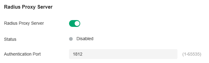
|
Radius Proxy Server |
Toggle on to enable the Radius Proxy Server. |
|---|---|
|
Status |
Displays the current status of the server. |
|
Authentication Port |
Specify the port that the controller listens for to receive radius messages from devices. |
Account Security
Launch the controller and access the Global View. Go to Settings > Account Security.
Two-Factor Authentication (2FA)
You can enable Two-Factor Authentication (2FA) to improve the security of the controller.
.png)
_20251222073701w.png)
|
Two-Factor Authentication (2FA) |
This function improves the security of the controller by requiring two factors of identification to access resources and data. With this function enabled, all accounts will be forced to enable 2FA upon user login. You can also enable 2FA for accounts on the Accounts > User page. |
|---|
Controller IP Access Rules
You can enable Controller IP Access Rules, so that only the IPv4 addresses you specified can access the controller locally. IPv6 addresses will be blocked.
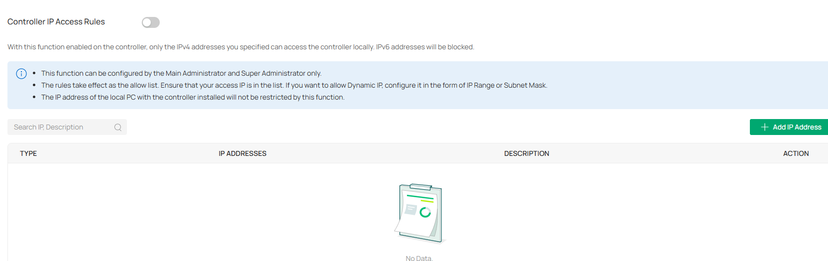
|
Type |
Specify the IP address type: Single IP Address, Single Subnet Mask, or IP Range. |
|---|---|
|
IP Addresses |
Specify the IP addresses that are allowed to access the controller. |
|
Description |
Enter a description for identification. |
Platform Integration
Open API
Overview
Omada’s Open API supports the REST API of most Controller services. This feature allows Omada users to write custom applications, embed APIs, or combine their own applications. The REST API supports HTTP GET and POST operations by providing specific URLs for each query, and the output of these operations is returned in JSON format.
To access the API securely, the Omada API framework supports the OAuth protocol for authentication and authorization, and supports the authorization code mode and client mode.
Access Token provides temporary and secure access to the API. For security reasons, Access Token has a limited lifespan. Access Token in authorization code mode uses the refresh API to obtain a new Access Token, and client mode obtains a new token through clientKey and clientSecret.
To use the Open API function, first create a new application, the smallest API access unit, which can be specified as client mode or authorization code mode. After creation, you can configure your own application for Open API access.
Configuration
1. In Global View, go to Settings > Platform Integration > Open API.
2. Click Add New App.
3. Specify the App name, choose the access mode and configure the parameters.
• Authorization code mode
The authorization code grant type is used to obtain both access tokens and refresh tokens and is optimized for confidential clients. Since this is a redirection-based flow, the client must be capable of interacting with the resource owner’s user-agent (typically a web browser) and capable of receiving incoming requests (via redirection) from the authorization server.

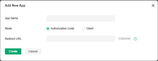
|
Redirect URL |
Specify the redirect URL for Oauth2.0 authorization flow. |
|---|
• Client mode
The client can request an access token using only its client credentials (or other supported means of authentication) when the client is requesting access to the protected resources under its control, or those of another resource owner that have been previously arranged with the authorization server (the method of which is beyond the scope of this specification).

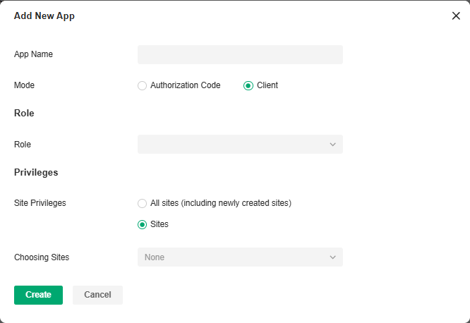
|
Role |
Specify the authority role of the client through the Open API. |
|---|---|
|
Site Privileges |
Specify the site privileges of the client through the Open API. |
4. Apply the settings. The application will be added for Open API access.
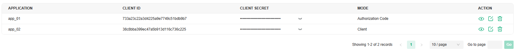
For more instructions, click Online API Document in the upper right corner of the web page to get the Open API Access Guide.
Webhooks
Overview
Webhook is an API concept and one of the usage paradigms of microservice APIs. It is also called a reverse API, that is, the front end does not actively send requests, but is completely pushed by the back end. In Omada, Webhook is used for the active push function of messages such as alerts.
Configuration
1. In Global View, go to Settings > Platform Integration > Webhooks.
2. Click Create New Webhook.

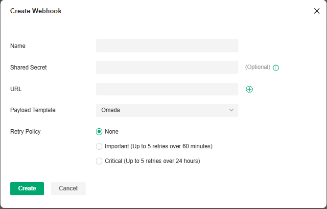
|
Name |
Specify the Webhook entry name. |
|---|---|
|
Shared Secret |
Specify the authentication secret key. If it is not filled in, the system will automatically generate a key. If it is manually cleared, the system will no longer generate a key. |
|
URL |
Specify the Webhook URL address. |
|
Payload Template |
Select a template for message push. |
|
Retry Policy |
Specify the Webhook retry policy: None (no retry), Important (up to 5 retries over 60 minutes), and Critical (up to 5 retries over 24 hours). |
3. Save the settings. The webhook entry will be added.

You can click the icon in the ACTION column to test the connectivity, view the dispatch logs, and edit, or delete the Webhook entry.
SAML SSO
Overview
SAML (Security Assertion Markup Language) SSO (Single Sign On) enables clients to access multiple web applications using one set of login credentials. To complete the SAML SSO interconnection, the system administrator needs to configure the IdP (identity provider) information when the current system serves as the SP (service provider), or configure the SP information when the current system serves as the IdP.
Prerequisites
• This chapter takes the configuration of the current system as an example to explain the operation. Other systems also need to be configured. SAML SSO works only after all systems are configured.
• If you need to connect with other systems that serve as the IdP, please obtain the metadata file of the IdP first, then configure the SP.
• If you need to connect with a third-party IdP, please configure the third-party IdP first and obtain its metadata file.
Configuration
1. Configure the SAML user group.
a. In Global View, go to Accounts > SAML User Group.
b. Click Add New SAML User Group. Configure the parameters and click Create.
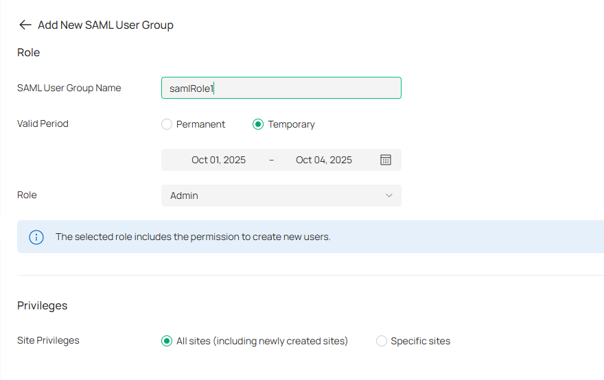
|
SAML User Group Name |
Specify the role name. |
|---|---|
|
Valid Period |
Set the validity period of the user. Permanent: The user account will have permissions permanently unless modified or deleted. Temporary: The user account will have permissions only in the period you set. Note that Temporary Users don’t have account-related permissions, including permissions such as User Manager, Roles Manager, SAML User Group Manager, SAML Users Manager, and SAML SSO Manager. |
|
Role |
Specify the authority role of the account. |
|
Site Privileges |
Specify the site privileges of the client through the Open API. |
2. Configure the IdP.
Use a third-party system as the IdP and follow the steps below to configure the parameters:
a. Create an IdP. Fill in the initial information except the name.
b. Use the IdP metadata information for SP configuration on the Controller.
c. Edit the IdP information, including Entity ID, Sign-On URL, and Relay State.
Note:
• The above three parameters use the information of View SAML Attribute in SP configuration.
• Relay State is base64(resourceId_omadaId).
d. Edit the Attribute, and configure the username and usergroup_name. The usergroup_name is the SAML User Group Name you configured in step 1.
3. Configure the SP.
Use the Controller as the SP and follow the steps below to configure the parameters:
a. In Global View, go to Settings > SAML SSO.
b. Click Add New SAML Connection.

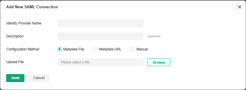
|
Identity Provider Name |
Specify the IdP name. |
|---|---|
|
Description |
Enter a description for identification. |
|
Configuration Method |
Configure the metadata. You can upload the metadata file, use URL parsing, or manually fill in the information. |
c. Click View SAML Attribute to view the SP configuration. This will be used for IdP configuration on the third-party system.
Subsequent Processing
After configuring all systems, verify whether the SAML SSO configuration is successful as follows:
1. In the configured IdP system, find the SP login entry and click to log in.
2. On the login page, enter the Username and Password to log in.
3. Go to the SP system and verify that the user has logged in.
For more instructions, refer to How to Configure SAML SSO on Omada Controller.
Maintenance
You can back up the configuration and data of your controller to prevent any loss of important information.
If necessary, restore the controller to a previous status using the backup file.
Restore
Launch the controller and access the Global View. Go to Settings > Maintenance. In Restore, click Browse and select a backup file from your computer or file server. Click Restore.

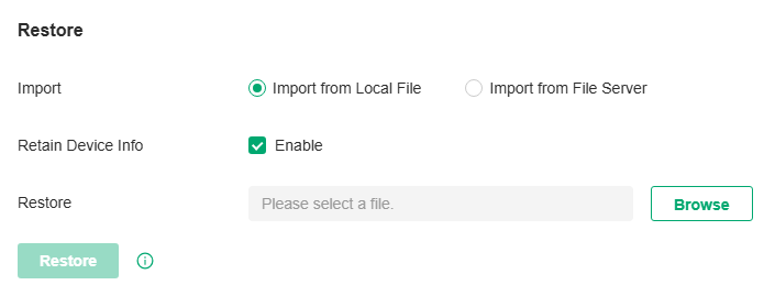
Note:
• The controller will be restored to the selected file and all current configurations will be lost.
• Only the configuration file of controller v5.0.x or above is supported.
• The current controller only supports the configuration file of the controller with the same or a smaller first-three-part version number (Major.Minor.Patch).
|
Import |
Select where you store the restore file. Import from Local File: Import the data locally. It is not supported when accessing the controller via cloud. Import from File Server: Import the data from a file server. Select the desired file server type (FTP / TFTP / SFTP / SCP) and configure the parameters. |
|---|---|
|
Retain Device Info |
Select this option if you want to retain device information. |
|
Restore |
Select the backup file to restore the information. |
Backup
Launch the controller and access the Global View. Go to Settings > Maintenance. In Backup, click Export to export and save the backup file.
If you want to export the data to a file server, configure the parameters accordingly and click Export.

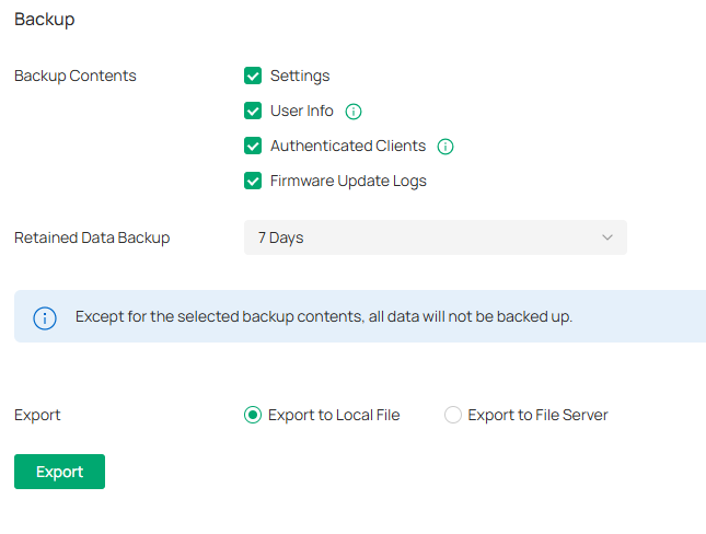
|
Backup Contents |
Select the data contents to back up. Settings: All the controller settings will be backed up. User Info: All local and cloud user information except for the main admin will be retained. Make sure Cloud Access is enabled on the Controller to be restored. Otherwise the Cloud account will not be retained correctly. Authenticated Clients: The authenticated client information will be backed up and can be used to verify clients for portal authentication. It is recommended to select this option if your network uses portal authentication. Firmware Update Logs: The firmware update logs will be backed up. |
|---|---|
|
Retained Data Backup |
Select the length of time in days that data will be backed up. 7 Days/30 Days/60 Days/90 Days/180 Days/365 Days: Back up the data in the recent days. All Time: (Only for Software Controller) Back up all data in the controller. |
|
Export |
Select where you want to export the data to. Export to Local File: Export and save the data locally. It is not supported when accessing the controller via cloud. Export to File Server: Export and save the data to a file server. Select the desired file server type (FTP / TFTP / SFTP / SCP) and configure the parameters. |
Backup Schedule
With Backup Schedule enabled, the controller will be scheduled to back up the configurations and data automatically at the specified time. You can easily restore the configurations and data when needed.
Note:
On Omada Cloud-Based Controller, there is no need to configure Backup Schedule. It will automatically save the configurations and data on the cloud.
Launch the controller and access the Global View. Go to Settings > Maintenance. In Backup Schedule, enable Backup Schedule and configure the parameters. Click Save.
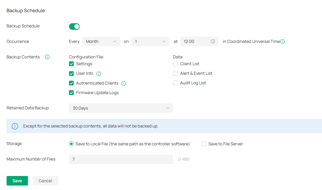
|
Occurrence |
Specify when to perform Auto Backup regularly. Select Every Day, Week, Month, or Year first and then set a time to back up files. Note the time availability when you choose Every Month. For example, if you choose to automatically backup the data on the 31st of every month, Backup Schedule will not take effect when it comes to the month with no 31st, such as February, April, and June. |
|---|---|
|
Backup Contents |
Select the data contents to back up. Settings: All the controller settings will be backed up. User Info: All locPast Connectionsal and cloud user information except for the main admin will be retained. Make sure Cloud Access is enabled on the Controller to be restored. Otherwise the Cloud account will not be retained correctly. Authenticated Clients: The authenticated client information will be backed up and can be used to verify clients for portal authentication. It is recommended to select this option if your network uses portal authentication. Firmware Update Logs: The firmware update logs will be backed up. Known Clients: Back up the list of the known clients. Past Connections: Back up the list of the past connections. To export past connections data, you need to first enable Client’s History Data in 5.4 History Data Retention. Logs: Back up the list of the logs. Audit Log List: Back up the list of the audit logs. |
|
Retained Data Backup |
Select the length of time in days that data will be backed up. 7 Days/30 Days/60 Days/90 Days/180 Days/365 Days: Back up the data in the recent days. All Time: (Only for Software Controller) Back up all data in the controller. |
|
Storage |
Select where you want to save the backup file. Save to Local File: The backup file will be saved as a local file. Save to File Server: The backup file will be saved in the specified file server. |
|
Saving Path |
(Only for Hardware Controller) Select a path to save the backup files. |
|
Maximum Number of Files |
(When selecting Save to Local File) Specify the maximum number of backup files to save. |
|
Type |
(When selecting Save to File Server) Specify the file server you are using. Four types of file server are available: FTP, TFTP, SFTP, and SCP. |
|
Server Hostname/IP |
(When selecting Save to File Server) Specify the Hostname/IP corresponding to the file server. |
|
Port |
(When selecting Save to File Server) Specify the port corresponding to the file server. |
|
FTP Username |
(When selecting FTP as File Server) Specify the username of the FTP file server. |
|
FTP Password |
(When selecting FTP as File Server) Specify the password of the FTP file server. |
|
SFTP Username |
(When selecting SFTP as File Server) Specify the username of the SFTP file server. |
|
SFTP Password |
(When selecting SFTP as File Server) Specify the password of the SFTP file server. |
|
SCP Username |
(When selecting SCP as File Server) Specify the username of the SCP file server. |
|
SCP Password |
(When selecting SCP as File Server) Specify the password of the SCP file server. |
|
File Path |
(When selecting Save to File Server) Specify the file path. |
You can view the name, backup time and size of backup files in Backup Files List.
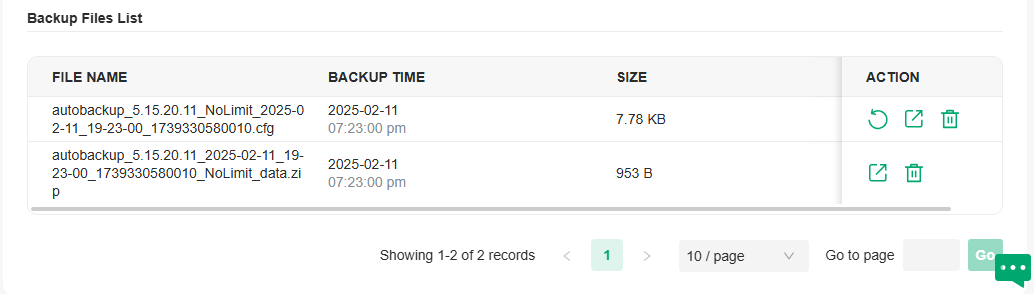
To restore, export or delete the backup file, click the icon in the Action column.
|
|
Restore the configurations and data in the backup file. All current configurations will be replaced after the restoration. To keep the backup data safe, please wait until the operation is finished. This will take several minutes. |
|
|
Export the backup file. The exported file will be saved in the saving path of your web browser. |
|
|
Delete the backup file. |
Note:
If the backup file is saved to file server and the type SCP / TFTP is selected, it will not included in the Backup Files List, and it cannot be exported, restored, or deleted.
Migration
Migration services allow users to migrate the configurations and data to any other controller. Migration services include Site Migration and Controller Migration, covering all the needs to migrate both a single site and the whole controller.
Site Migration
Overview
Site Migration allows the administrators to export a site from the current controller to any other controller that has the same version. All the configurations and data of the site will be migrated to the target controller.
The process of migrating configurations and data from a site to another controller can be summarized in three steps: Export Site, Migrate Site and Migrate Devices.
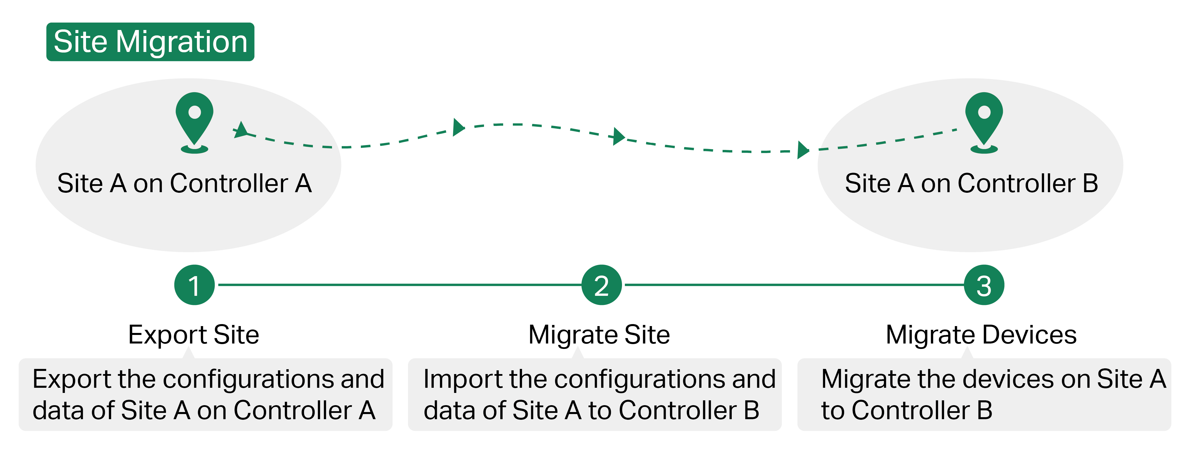
Step 1: Export Site
Export the configurations and data of the site to be migrated as a backup file.
Step 2: Migrate Site
In the target controller, import the backup file of the original site.
Step 3: Migrate Devices
Migrate the devices which are on the original site to the target controller.
Configuration
To migrate a site to another controller, follow these steps below.
Note:
The connection to internet will be lost for several minutes during the migration. Clients need to connect the wireless network again after the migration is completed. Please choose the time to start migration operation carefully.
Step 1: Export Site
1. Launch the controller and access the Global View. Go to Settings > Migration. On the Site Migration tab, click the start button.
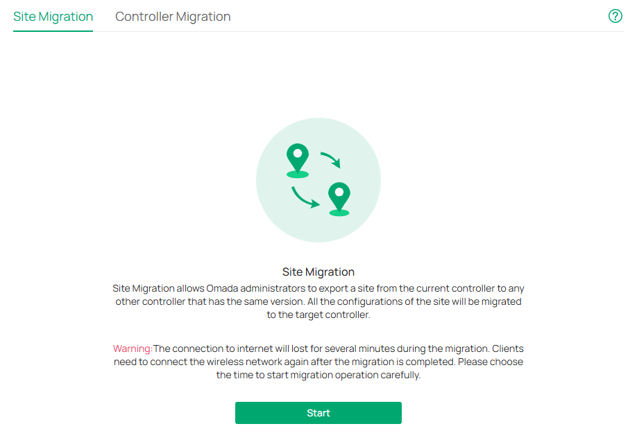
2. Select the site to be imported into the second controller in the Select Site drop-down list. Select where you want to export and save the backup file. Click Export to download the file of the current site. If you have backed up the file, click Skip.

Step 2: Migrate Site
1. Start and log in to the target controller, access the Global View, go to Dashboard > Site List, and click Import Site to upload the backup file of your site, and then the following window will pop up. Note that for organization v5.13.11.41 and above, only the configuration file from the organization with the same first-three-part version number (Major.Minor.Patch) can be imported.

2. Enter a unique name for the new site. Click Browse to upload the file of the site to be imported and click Import to import the site.
3. After the file has been imported to the target controller, go back to the previous controller and click Confirm.
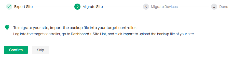
Step 3: Migrate Devices
1. Enter the IP address or URL of your target controller into Controller IP/Inform URL input filed. In this case, the IP address of the target controller is 10.0.3.23.
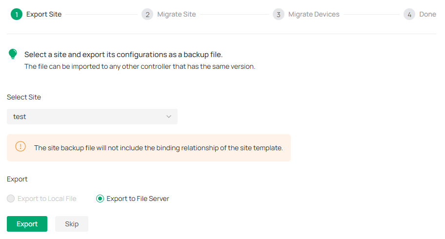
Note:
Make sure that you enter the correct IP address or URL of the target controller to establish the communication between managed devices and your target controller. Otherwise the managed devices cannot be adopted by the target controller.
2. Select the devices that are to be migrated by clicking the box next to each device. By default, all the devices are selected. Click Migrate Devices to migrate the selected devices to the target controller.
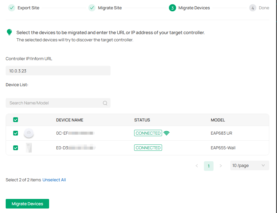
3. Verify that all the migrated devices are visible and connected on the target controller. When all the migrated devices are in Connected status on the Device page on the target controller, click Forget Devices to finish the migration process.
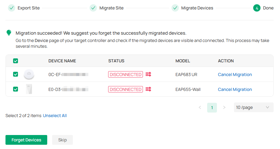
4. When the migration process is completed, all the configuration and data are migrated to the target controller. You can delete the previous site if necessary.
Controller Migration
Overview
Controller Migration allows administrators to migrate the configurations and data from the current controller to any other controller that has the same version.
The process of migrating configurations and data from the current controller to another controller can be summarized in three steps: Export Controller, Migrate Controller and Migrate Devices.

Step1: Export Controller
Export the configurations and data of the current controller as a backup file.
Step2: Migrate Controller
In the target controller, import the backup file of the current controller.
Step3: Migrate Devices
Migrate the devices on the current controller to the target controller.
Configuration
To migrate your controller, follow these steps below.
Note:
The connection to internet will be lost for several minutes during the migration. Clients need to connect the wireless network again after the migration is completed. Please choose the time to start migration operation carefully.
Step1: Export Controller
1. Launch the controller and access the Global View. Go to Settings > Migration. On the Controller Migration tab, click the start button on the following page.
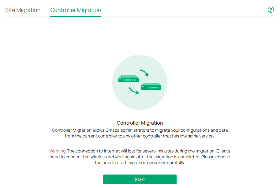
2. Select the length of time in days that data will be backed up in the Retained Data Backup, and where you want to export and save the data. Click Export to export the configurations and data of your current controller as a backup file. If you have backed up the file, click Skip.
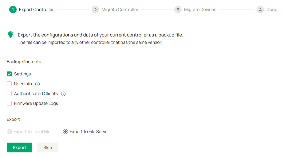
Step2: Migrate Controller
1. Log in to the target controller. Launch the controller and access the Global View. Go to Settings > Maintenance > Restore. Click Browse to locate and choose the backup file of the previous controller. Then click Restore to upload the file.

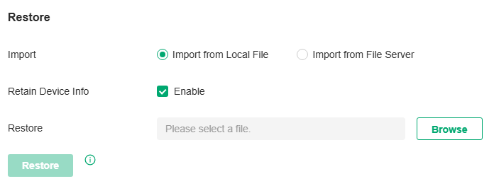
2. After the file has been imported to the target controller, go back to the previous controller and click Confirm.
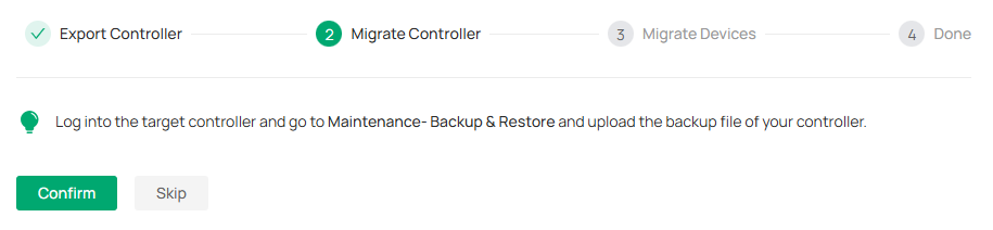
Step3: Migrate Devices
1. Enter the IP address or URL of your target controller into Controller IP/Inform URL input filed. In this case, the IP address of the target controller is 10.0.3.23.

Note:
Make sure that you enter the correct IP address or URL of the target controller to establish the communication between managed devices and your target controller. Otherwise the managed devices cannot be adopted by the target controller.
2. Select the devices that are to be migrated by clicking the box next to each device. By default, all the devices are selected. Click Migrate Devices to migrate the selected devices to the target controller.
3. Verify that all the migrated devices are visible and connected on the target controller. When all the migrated devices are in Connected status on the Device page on the target controller, click Forget Devices to finish the migration process.
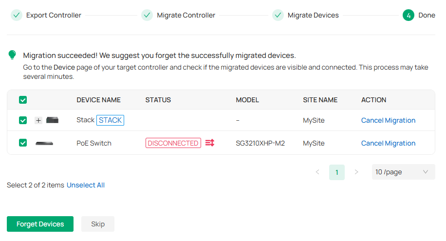
 When the migration process is completed, all the configuration and data are migrated to the target controller. You can uninstall the previous controller if necessary.
Export Data
You can export data to monitor or debug your devices.
Launch the controller and access the Global View. Go to Settings > Export Data. Select the type of data from the export list and click Export.
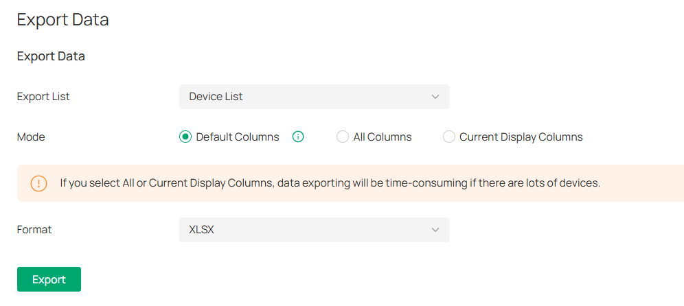
|
Export List |
Device List: Export the list of managed devices. Client List (All): Export the list of all clients that are connected to the networks. Alert & Event List: Export the list of the alerts and events. Audit Log List: Export the list of the audit logs. Authorized Client List: Export the list of authorized clients. Voucher Codes: Export the list of the voucher codes. Client Connection Records: Export the list of the client connection records. Threat Management: Export the list of the threat management data. |
|---|---|
|
Mode |
Select the columns to export. We recommend selecting Default Columns, which include commonly needed columns such as DEVICE NAME, MAC ADDRESS, MODEL, etc. If you select All Columns or Current Display Columns, data exporting will be time-consuming if there are lots of devices. |
|
Format |
The data can be exported to the file in the format of .CSV or .XLSX. |
Export for Support
In Export for Support, you can export configuration data and running logs for technical support to diagnose network problems. The exported data will not contain users’ personal information.
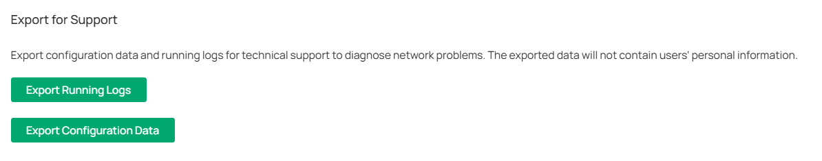
|
Export Running Logs |
Click to export running logs. |
|---|---|
|
Export Configuration Data |
Click to export configuration data. |
Note:
Configuration data cannot be imported into the controller through restore.
Auto Send Data to Email
In Auto Send Data to Email, you can send the data report to the specified email addresses regularly.
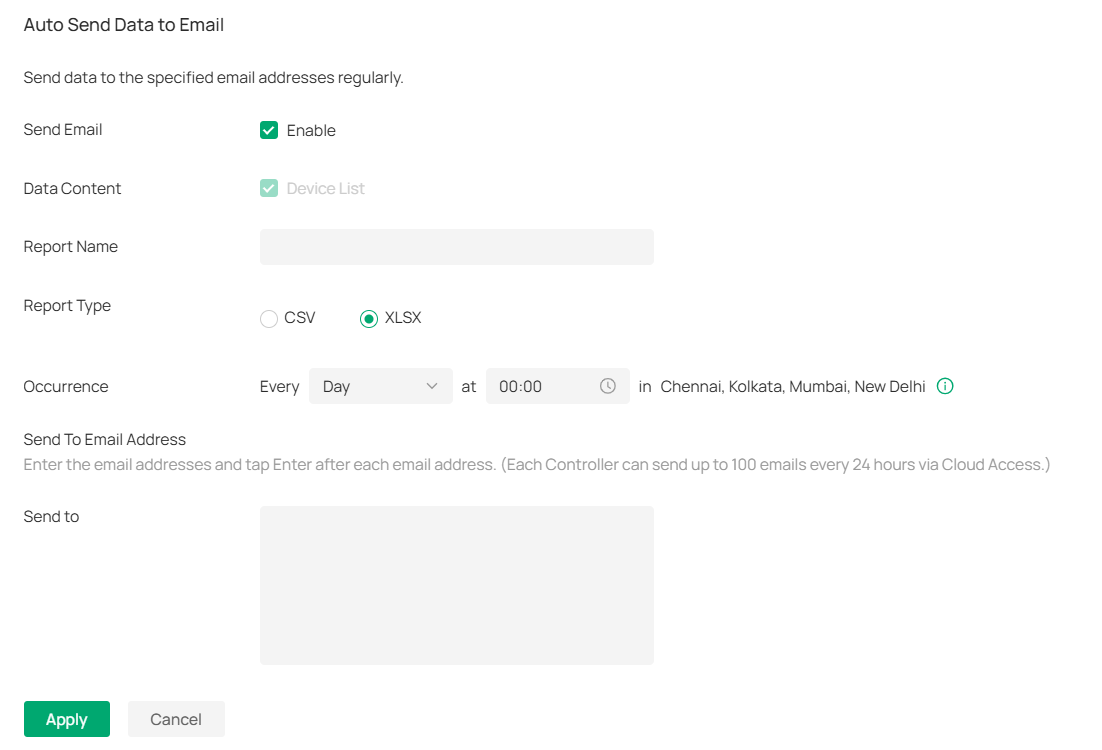
|
Data Content |
Specify the data content to send. |
|---|---|
|
Report Name |
Specify the name of the data report. |
|
Report Type |
Specify the file format of the data report. |
|
Occurrence |
Specify the time to send the data report. |
|
Send to |
Specify the email to send the data report. |
Note:
Cloud Access or SMTP is required to enable the Send Email feature.
Cloud Access
Overview
With Cloud Access, it is convenient for you to manage your controller from anywhere, as long as you have access to the internet.
Configuration
To manage your controller from anywhere, follow these steps:
1. Prepare your controller for Cloud Access
■ For Software Controller / Hardware Controller:
Note:
• Before you start, make sure your Software Controller Host or Hardware Controller has access to the internet.
• If you have enabled cloud access and bound your TP-Link ID in the quick setup wizard, skip this step.
1) Launch the controller and access the Global View. Go to Settings > Cloud Access. Enable Cloud Access.

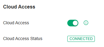
2) Enter your TP-Link ID and password. Then click Log In and Bind.
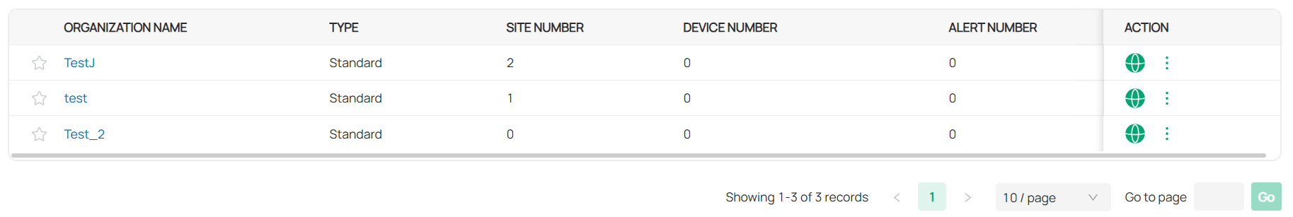
■ For Cloud-Based Controller
Your Cloud-Based Controller is based on the Cloud, so it is naturally accessible through Cloud Service. No additional preparation is needed.
2. Access your controller through Cloud Service
Go to https://omada.tplinkcloud.com and login with your TP-Link ID and password. A list of controllers that have been bound with your TP-Link ID will appear. Then click the launch icon in the Action column to manage the controller.

Configuring General Network Settings
This chapter guides you on how to configure general network settings with the SDN Controller.
Configure Site Settings
1. Launch the controller and access a site.
2. Go to Network Config > General Settings > Site Settings.
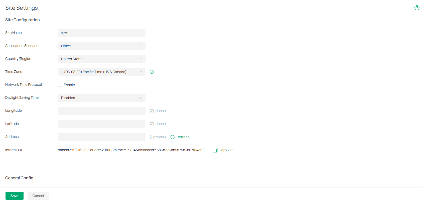
3. Configure the parameters according to actual site needs.
• Site Configuration
In Site Configuration, you can view and modify the site name, location, time zone, and application scenario of the current site.
|
Site Name |
Specify the name of the current site. It should be no more than 64 characters. |
|---|---|
|
Application Scenario |
Specify the application scenario of the site. To customize your scenario, click Create New Scenario in the drop-down list. |
|
Country/Region |
Select the location of the site. |
|
Time Zone |
Select the time zone of the site. |
|
Network Time Protocol |
Enter the IP address(es) of the NTP (Network Time Protocol) server. NTP server assigns network time to the EAP devices. |
|
Daylight Saving Time |
Enable the feature if your country/region implements DST. |
|
Time Offset |
Select the time added in minutes when Daylight Saving Time starts. |
|
Starts On |
Specify the time when the DST starts. The clock will be set forward by the time offset you specify. |
|
Ends On |
Specify the time when the DST ends.The clock will be set back by the time offset you specify. |
|
Longitude / Latitude / Address |
Configure the parameters according to where the site is located. These fields are optional. |
|
Inform URL |
Site Inform URL adds site information based on the Controller Inform URL to informs devices of the controller’s URL or IP address as well as site info. Then the devices make contact with the controller so the controller can discover them and adopt them to the site. |
In General Config, you can control the LED status of devices in the site, remember all devices in the site, configure the controller to send generated system logs to the log server.
Wireless features include Mesh, Auto Failover, Connectivity Detection, Full-Sector DFS, EAP LLDP, Fast Roaming, Non-Stick Roaming, AI Roaming, Band Steering, Multicast/Broadcast Rate Limit and Beacon Control. They are applicable to APs and wireless gateways/routers. With these wireless features configured properly, you can improve the network’s stability, reliability and communication efficiency.
Wireless features are recommended to be configured by network administrators with the WLAN knowledge. If you are not sure about your network conditions and the potential impact of all settings, keep Wireless Features as their default configurations.
|
When enabled, APs supporting Mesh can establish the mesh network at the site. |
|
|
Auto Failover |
(For APs in the mesh network) Auto Failover is used to automatically maintain the mesh network. When enabled, the controller will automatically select a new wireless uplink for the AP if the original uplink fails. To enable this feature, enable Mesh first. |
|
Connectivity Detection |
(For APs in the mesh network) Specify the method of Connection Detection when mesh is enabled. In a mesh network, the APs can send ARP request packets to a fixed IP address to test the connectivity. If the link fails, the status of these APs will change to Isolated. Auto (Recommended): Select this method and the mesh APs will send ARP request packets to the default gateway for the detection. Custom IP Address: Select this method and specify a desired IP address. The mesh APs will send ARP request packets to the custom IP address to test the connectivity. If the IP address of the AP is in different network segments from the custom IP address, the AP will use the default gateway IP address for the detection. |
|
Full-Sector DFS |
(For APs in the mesh network) With this feature enabled, when radar signals are detected on current channel by one AP, the other APs in the mesh network will be also informed. Then all APs in the mesh network will switch to an alternate channel. To enable this feature, enable Mesh first. |
|
EAP LLDP |
Click the checkbox to enable EAP LLDP (Link Layer Discovery Protocol) for device discovery and auto-configuration of VoIP devices. |
|
Fast Roaming |
With this feature enabled, wireless clients that support 802.11k/v can improve fast roaming experience when moving among different APs and wireless gateways/routers. By default, it is disabled. This feature is available for some certain devices. |
|
Non-Stick Roaming |
This feature helps disconnect “sticky clients” receiving weak signals from their suboptimal Wireless Device, allowing them to switch to a superior Wireless Device and improve network efficiency. Note that this may cause temporary disconnections or hinder re-association in rare cases. |
|
Ping-Pong Roaming Suppression |
This feature helps prevent clients from frequently roaming between two APs in areas where weak signals overlap, thereby improving connection stability. Note that this may cause clients not able to connect to certain AP in rare cases, and also may dynamic change tx power of AP. |
|
AI Roaming |
With Fast Roaming enabled, you can enable AI Roaming to facilitate Fast Roaming, which improves roaming experience of the wireless clients that support 802.11k/v. This feature is available for certain models. |
|
Band Steering |
Band steering can adjust the number of clients in 2.4 GHz, 5 GHz and 6 GHz bands to provide better wireless experience. When enabled, multi-band clients will be steered to the 5 GHz and 6 GHz band according to the configured parameters. This function can improve the network performance because the 5 GHz and 6 GHz band supports a larger number of non-overlapping channels and is less noisy. |
|
Multicast/Broadcast Rate Limit |
With rate limit configured for Other Multicast, multicast services such as multicast video will be affected. |
|
Management Frame Control |
Beacons are transmitted periodically by the AP and wireless gateway/router to announce the presence of a wireless network for the clients. Click Beacon Interval: Specify how often the APs and wireless gateways/routers send a beacon to clients. By default, it is 100. DTIM Period: Specify how often the clients check for buffered data that are still on the AP or wireless gateway/router awaiting pickup. By default, the clients check for them at every beacon. DTIM (Delivery Traffic Indication Message) is contained in some Beacon frames indicating whether the AP or wireless gateway/router has buffered data for client devices. An excessive DTIM interval may reduce the performance of multicast applications, so we recommend that you keep the default interval, 1. RTS Threshold: RTS (Request to Send) can ensure efficient data transmission by avoiding the conflict of packets. If a client wants to send a packet larger than the threshold, the RTS mechanism will be activated to delay packets of other clients in the same wireless network. We recommend that you keep the default threshold, which is 2347. If you specify a low threshold value, the RTS mechanism may be activated more frequently to recover the network from possible interference or collisions. However, it also consumes more bandwidth and reduces the throughput of the packet. Airtime Fairness: With this option enabled, each client connecting to the AP or wireless gateway/router can get the same amount of time to transmit data so that low-data-rate clients do not occupy too much network bandwidth and network performance improves as a whole. We recommend you enable this function under multi-rate wireless networks. Probe Response Maximum Retransmission: Set the maximum number that the AP retransmits probe responses if it does not receive a client acknowledgment. When a client sends a probe request to detect the network, the AP responds with a probe response. However, factors like interference, long distance, or mobile devices (such as passing clients) may cause response loss and trigger retransmissions. Frequent invalid retransmissions in high-density scenarios will occupy wireless channel resources. It is recommended to keep the default value of 1 to balance reliability and efficiency. Probe Response Threshold: When enabled, the AP will filter probe requests with signal strength below the set threshold and stop responding, which may affect weak signal terminals from discovering the network. It is recommended to enable this feature only in high-density scenarios and select the Auto mode to optimize efficiency. In Auto mode, the AP dynamically calculates the threshold based on historical coverage data to avoid wasting wireless resources for devices in non-target areas. In Custom mode, you need to set the threshold manually. |
You can specify a device account for all adopted devices on the site in batches. Once the devices are adopted by the controller, their username and password become the same as settings in Device Account to protect the communication between the controller and devices. By default, the username is admin and the password is generated randomly.
|
Username / Password |
Enter a username and password for all devices in the site. The new username and password will be applied to all the managed devices. For newly adopted devices, once they are adopted by the controller, their username and password becomes the same as settings in device account. |
|---|
• Auto Send Data to Email
In Export Data, you can export the data of the Controller to monitor or debug the connected devices.
|
Send Email |
Check the box to enable automatic data report. |
|---|---|
|
Data Content |
Specify the content of data report. |
|
Report Name |
Specify the name of data report. |
|
Report Type |
Specify the file format of data report: csv or xlsx. |
|
Occurrence |
Set the time to send the data report. |
|
Send To Email Address |
Enter the email addresses to send the data reports. Press Enter after each email address to separate them. (Each Controller can send up to 100 emails every 24 hours via Cloud Access.) |
Configure SSH Settings
Overview
SSH (Secure Shell) provides a method for you to securely configure and monitor network devices via a command-line user interface on your SSH terminal.
Note:
If you use an SSH terminal to manage devices which are managed by the controller, you can only get the User privilege.
Configuration
Launch the controller and access a site. Go to Network Config > General Settings > SSH. Enable SSH Login globally and configure the parameters. Then click Apply.
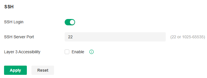
|
SSH Server Port |
Specify the SSH Sever Port which your network devices use for SSH connections. You need to configure the SSH Server Port correspondingly on your SSH terminal. |
|---|---|
|
Layer 3 Accessibility |
With this feature enabled, the SSH terminal from a different subnet can access your devices via SSH. With this feature disabled, only the SSH terminal in the same subnet can access your devices via SSH. |
Configure Reboot Schedules
Overview
Reboot Schedule can make your devices reboot periodically according to your needs. You can configure Reboot Schedule flexibly by creating multiple Reboot Schedule entries.
Configuration
1. Launch the controller and access a site.
2. Go to Network Config > General Settings > Schedule > Reboot Schedule.
3. Click Create New Reboot Schedule to load the following page and configure the parameters.
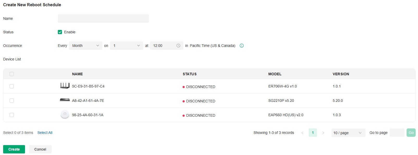
|
Name |
Enter the name to identify the Reboot Schedule entry. |
|---|---|
|
Status |
Enable or disable the Reboot Schedule entry. |
|
Occurrence |
Specify the date and time for the devices to reboot. |
|
Devices List |
Select the devices which the Reboot Schedule applies to. |
4. Click Create. The new Reboot Schedule entry will be added to the table.
Configure Port Schedules
Overview
In Port Schedule, you can set schedules to control the PoE feature of the PoE switch or control the on/off behavior of the switch port. When the PoE feature is disabled, the PoE switches will not supply power to the connected PoE devices during the specified time period, but the switches can still transmit data; when the Port feature is disabled, please check your topology and related configurations to avoid network problems. You can configure PoE or Port Schedule flexibly by creating multiple entries.
Configuration
1. Launch the controller and access a site.
2. Go to Network Config > General Settings > Schedule > Port Schedule.
3. Click Create New Port Schedule to load the following page and configure the parameters.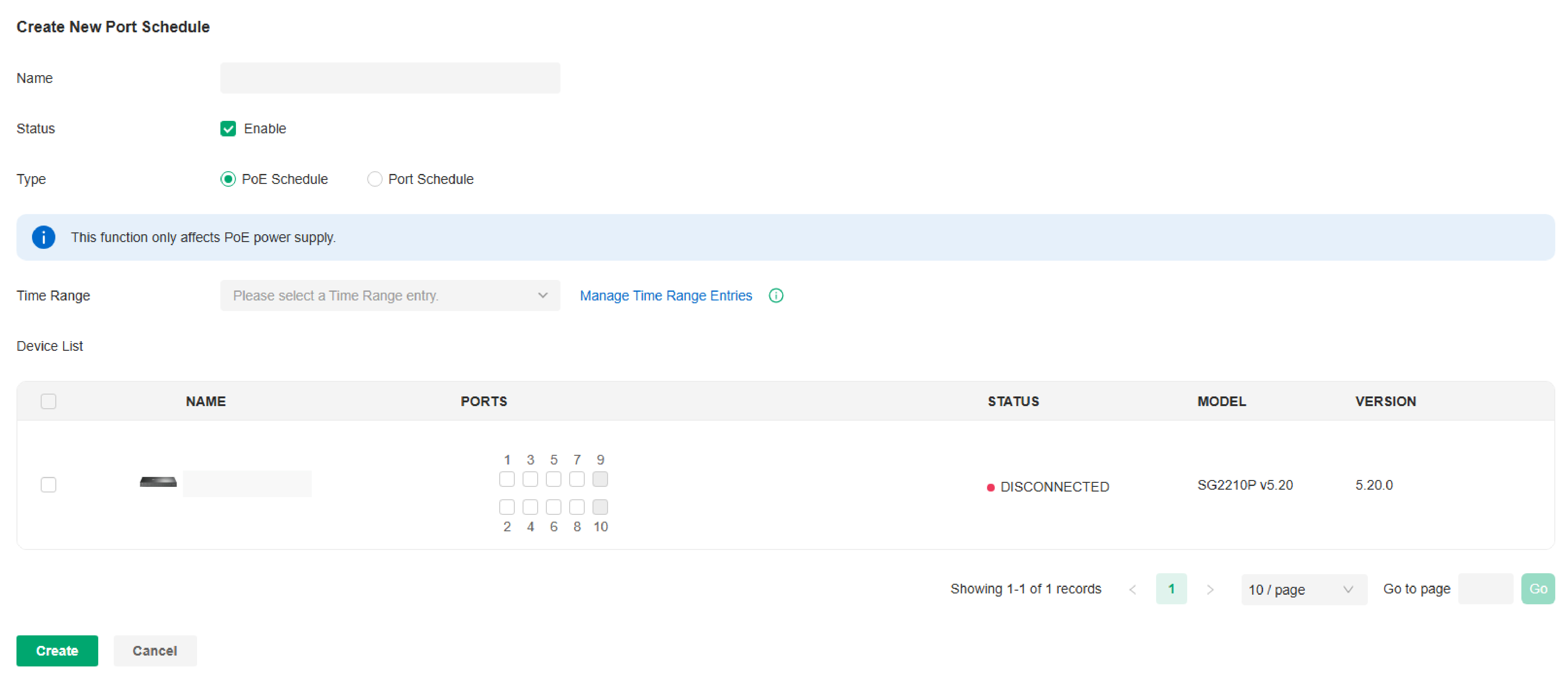
|
Name |
Enter the name to identify the schedule entry. |
|---|---|
|
Status |
Enable or disable the schedule entry. |
|
Type |
Type:Specify the schedule type: PoE Schedule: This function only affects PoE power supply. Port Schedule: This function affects LAN connections of ports but does not affect PoE power supply. To avoid network problems, please check your topology and related configurations before turning off ports. |
|
Time Range |
When the Type is PoE Schedule, select the time range when the PoE switches will supply power to the powered devices. when the Type is Port Schedule, select the time range when the switches will turn on the designated ports. You can create a Time Range entry by clicking Create New Time Range Entry from the drop down list. |
|
Devices List |
When Type is PoE Schedule, select the PoE switch and PoE port to apply the schedule. When Type is Port Schedule, select the switch and port to apply the schedule. |
4. Click Create. The new schedule entry will be added to the table.
Configure mDNS Settings
Overview
mDNS (Multicast DNS) Repeater can help forward mDNS request/reply packets between different VLANs. With this function, you can create a forwarding rule to allow the devices in the specified Client VLAN to discover the mDNS service in the specified Service VLAN. You can also specify the services to be forwarded.
Configuration
1. Launch the controller and access a site. Go to Network Config > General Settings > mDNS.
2. Click Create New Rule. Configure the parameters.
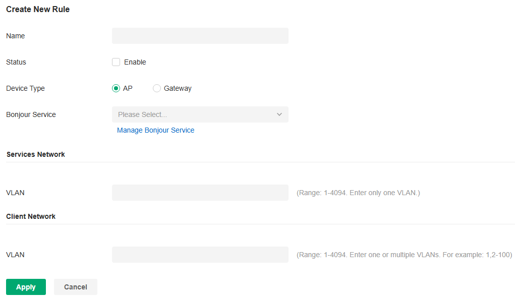
|
Name |
Specify the rule name for identification. |
|---|---|
|
Status |
Enable or disable this rule. |
|
Device Type |
Specify the device type for which the rule takes effect. |
|
Bonjour Service |
Specify the services to be forwarded. |
|
Services Network - VLAN |
When Device Type is AP, specify the VLANs where the mDNS services are located. You can enter VLAN ranges or VLAN IDs separated by comma. |
|
Client Network - VLAN |
When Device Type is AP, specify the VLANs where the Client devices are located. You can enter VLAN ranges or VLAN IDs separated by comma. |
|
Services Network - Network |
When Device Type is Gateway, specify the networks where the mDNS services are located. |
|
Client Network - Network |
When Device Type is Gateway, specify the networks where the Client devices are located. |
3. Apply the settings.
Configure Bonjour Service
Overview
mDNS (Multicast DNS) Repeater can help forward mDNS request/reply packets between different VLANs. With this function, you can create a forwarding rule to allow the devices in the specified Client VLAN to discover the mDNS service in the specified Service VLAN. You can also specify the services to be forwarded.
Configuration
To configure the Bonjour Service profiles, follow these steps:
1. Launch the controller and access a site.
2. Go to Network Config > General Settings > mDNS > Bonjour Service.
3. Click Create New Bonjour Service to add a new profile .

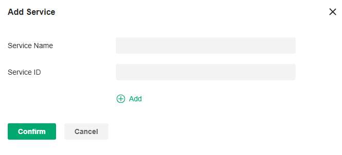
4. Configure the parameters.
|
Service Name |
Enter a name to identify the profile. |
|---|---|
|
Service ID |
Specify the domain name corresponding to the mDNS service. It is used to identify and filter mDNS packets. |
5. Click Apply to save the profile.
Configure SNMP Settings
Overview
SNMP (Simple Network Management Protocol) provides a convenient and flexible method for you to configure and monitor network devices. Once you set up SNMP for the devices, you can centrally manage them with an NMS (Network Management Station).
The controller supports multiple SNMP versions including SNMPv1, SNMPv2c and SNMPv3.
Note:
If you use an NMS to manage devices which are managed by the controller, you can only read but not write SNMP objects.
Configuration
1. Launch the controller and access a site.
2. Go to Network Config > General Settings > SNMP.
3. Configure the parameters. Then click Apply.
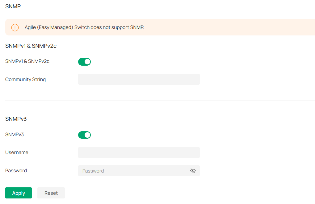
|
SNMPv1 & SNMPv2c |
Enable or disable SNMPv1 and SNMPv2c globally. |
|---|---|
|
Community String |
With SNMPv1 & SNMPv2c enabled, specify the Community String, which is used as a password for your NMS to access the SNMP agent. You need to configure the Community String correspondingly on your NMS. |
|
SNMPv3 |
Enable or disable SNMPv3 globally. |
|
Username |
With SNMPv3 enabled, specify the username for your NMS to access the SNMP agent. You need to configure the username correspondingly on your NMS. |
|
Password |
With SNMPv3 enabled, specify the password for your NMS to access the SNMP agent. You need to configure the password correspondingly on your NMS. |
Configure VoIP Settings
VoIP (Voice over Internet Protocol) allows you to make voice calls using a broadband Internet connection instead of a regular (or analog) phone line. You can configure the VoIP settings for your devices on Omada Central Essentials.
Call Settings
Overview
You can create telephony provider profiles, digit map profiles, call blocking profiles, and emergency number settings to facilitate telephony configurations.
Configuration
1. Launch the controller and access a site.
2. Go to Network Config > General Settings > VoIP > Call Settings.
3. Click Create New Provider Profile. Configure the parameters and click Create.
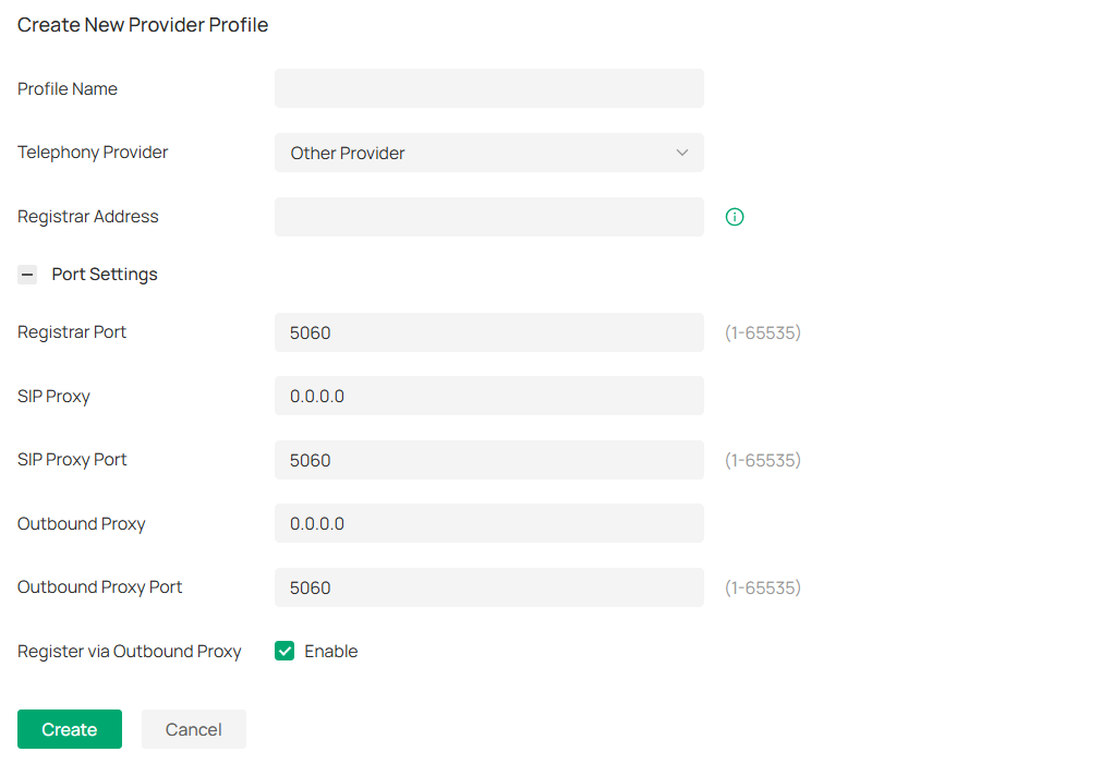
|
Profile Name |
Enter a name to identify the profile. |
|---|---|
|
Telephony Provider |
Choose your telephony provider, then enter the parameters specified by your provider. The parameters differ according to your selection. If your provider is not listed, choose Other Provider, then refer to the following to configure the parameters: |
|
Registrar Address |
Specify the registrar address specified by your provider. Usually it is a domain name, if not, an IP address. |
|
Registrar Port |
Specify the registrar port. Typically 5060, unless your provider specifies a different port. |
|
SIP Proxy |
Specify the IP address or URL of the SIP proxy server. |
|
SIP Proxy Port |
Specify the SIP proxy port. Typically 5060, unless your provider specifies a different port. |
|
Outbound Proxy |
Specify the IP address or URL of the outbound proxy server. |
|
Outbound Proxy Port |
Specify the outbound proxy port. Typically 5060, unless your provider specifies a different port. |
|
Register via Outbound Proxy |
When enabled, the connected VoIP devices will use the specified Outbound Proxy for SIP registration. When disabled, the connected VoIP devices will use the Registrar Address above for SIP registration. |
4. Configure other call settings according to actual site needs.
■ Digit Map
A digit map can be used to match digits to control phone numbers from being dialed. A phone number can be dialed out only when its digit sequence matches the digit map.
Click Create New Digit Map. Configure the parameters and click Create.
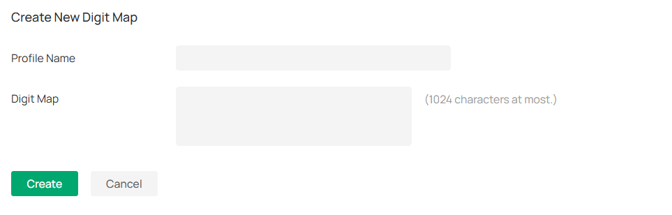
|
Profile Name |
Enter a name to identify the profile. |
|---|---|
|
Digit Map |
Enter a digit map by referring to the setting examples. |
■ Call Blocking
Call Blocking allows the connected VoIP devices to block unwanted incoming and outgoing calls.
Click Create New Call Blocking Profile. Configure the parameters and click Create.
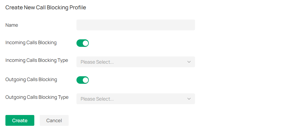
|
Profile Name |
Enter a name to identify the profile. |
|---|---|
|
Incoming Calls Blocking |
Enable this option to block unwanted incoming calls. |
|
Incoming Calls Blocking Type |
Specify the types of incoming calls to block. Specific Number: Specify one or more phone numbers to block incoming calls from them. Anonymous Number: Block all unknown incoming calls. |
|
Outgoing Calls Blocking |
Enable this option to block unwanted outgoing calls. |
|
Outgoing Calls Blocking Type |
Specify the types of outgoing calls to block. Mobile: Block outgoing calls to mobile numbers. Landline: Block outgoing calls to landline numbers. Long Distance: Block outgoing calls to long-distance numbers. International: Block outgoing calls to international numbers. Calls with specific number prefix: Specify one or more number prefixes to block outgoing calls to phone numbers with the prefixes. |
VoIP Devices
Overview
In VoIP Devices, you can configure and manage the connected VoIP devices.
Configuration
1. Launch the controller and access a site.
2. Go to Network Config > General Settings > VoIP > VoIP Devices.
3. Click the Telephony Settings icon. Configure the parameters and click Apply.

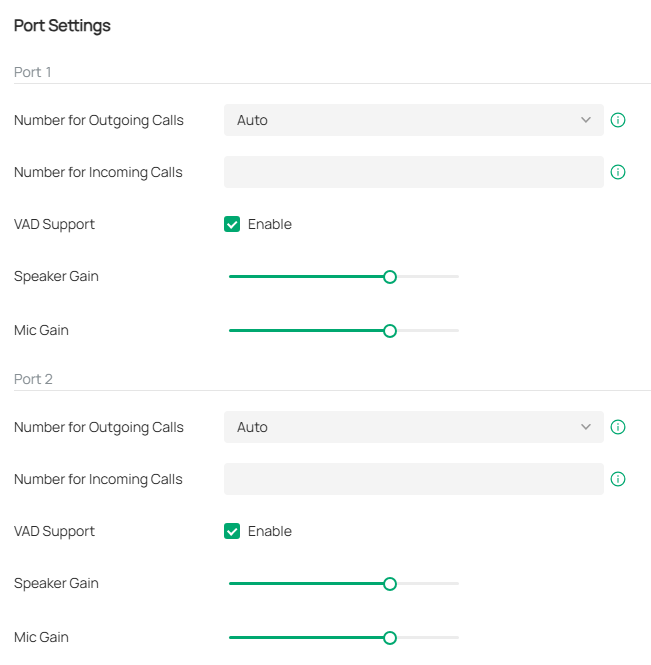
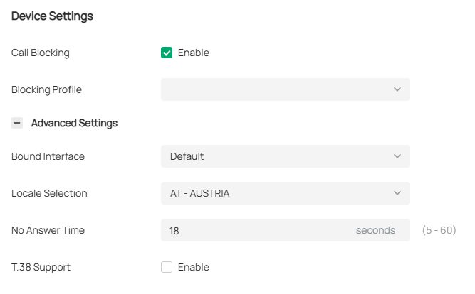

|
Number for Outgoing Calls |
Select the phone number used by your telephony device to make outgoing calls. The default is Auto, which means the device will automatically select an available phone number to make calls. |
|---|---|
|
Number for Incoming Calls |
Select the phone numbers used by your telephony device to receive incoming calls. The default is all registered numbers, which means the device can use all registered numbers to receive calls. |
|
VAD Support |
VAD (Voice Activity Detection) saves bandwidth consumption by avoiding transmission of silence packets. It also ensures that the bandwidth is reserved only when voice activity is activated. |
|
Speaker Gain |
Adjust the slider to control the speaker sound. |
|
Mic Gain |
Adjust the slider to control the microphone sound. |
|
Call Blocking |
Enable this function to block unwanted calls. |
|
Blocking Profile |
Select a blocking profile to block unwanted calls. |
|
Digit Map Profile |
Select a digit map profile to control phone numbers from being dialed. A phone number can be dialed out only when its digit sequence matches the digit map. |
|
Locale Selection |
Select your location. The system is embedded with the default location-based parameters such as ring tones. |
|
DSCP for SIP / DSCP for RTP |
DSCP (Differentiated Services Code Point) is the first 6 bits in the ToS (Type of Service) byte. DSCP marking allows you to ensure preferential treatment for higher-priority traffic on the network based on the DSCP value. Select DSCP for the SIP (Session Initiation Protocol) and RTP (Real-time Transport Protocol) respectively. If you are unsure, please keep the default value. |
|
DTMF Relay Setting |
Select a protocol for DTMF relay setting. If you are unsure of which one to select, please keep the default value. |
|
Registry Expiration Time |
Enter the expiration time of the SIP registration. |
|
Registry Retry Interval |
Enter the time duration for which the system sends a request to retry registering automatically prior to the Registry Expiration Time. If you are unsure, please keep the default value. |
|
T.38 Support |
Select the check box to enable T.38 support that allows fax documents to be transferred in real-time between two standard Group 3 facsimile terminals over the Internet or other networks using IP protocols. This function is only effective between two T.38-enabled terminals. |
|
End with # |
Select the check box to use the pound sign (#) as an end-of-dialing. |
VoIP Phone Number
Overview
On this page, you can configure phone numbers for VoIP-enabled devices on the current site.
Configuration
1. Launch the controller and access a site.
2. Go to Network Config > General Settings > VoIP > VoIP Phone Number.
3. Choose a method to add phone numbers:
■ Add phone numbers separately
Click Add. Configure the parameters and click Save.

|
PHONE NUMBER |
The number used to make calls. This number cannot be reused across different devices. |
|---|---|
|
USERNAME |
The account name used to register the phone number. Please enter it according to the registration server configuration. |
|
PASSWORD |
The authentication password used to register the phone number. Please enter it according to the registration server configuration. |
|
PROVIDER PROFILE |
Specify the provider profile associated with the phone number. The phone number will be registered on the corresponding server. |
|
DEVICE MAC |
Specify the VoIP device associated with the phone number. Up to eight phone numbers can be added to a device. |
|
STATUS |
Displays the phone number's registration status. |
|
ACTION |
Edit or delete an added phone number. |
■ Import phone numbers in batches
Click Import. Download the template and fill in your phone number information. Then import the file.
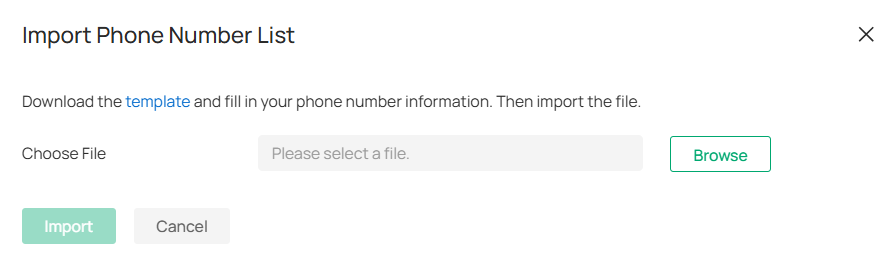
Call Logs
Overview
In Call Logs, you can record the details of incoming calls and outgoing calls.
Configuration
1. Launch the controller and access a site.
2. Go to Network Config > General Settings > VoIP > Call Logs.
3. Enable Call Logs and click Apply. The calls will be recorded in the table below.

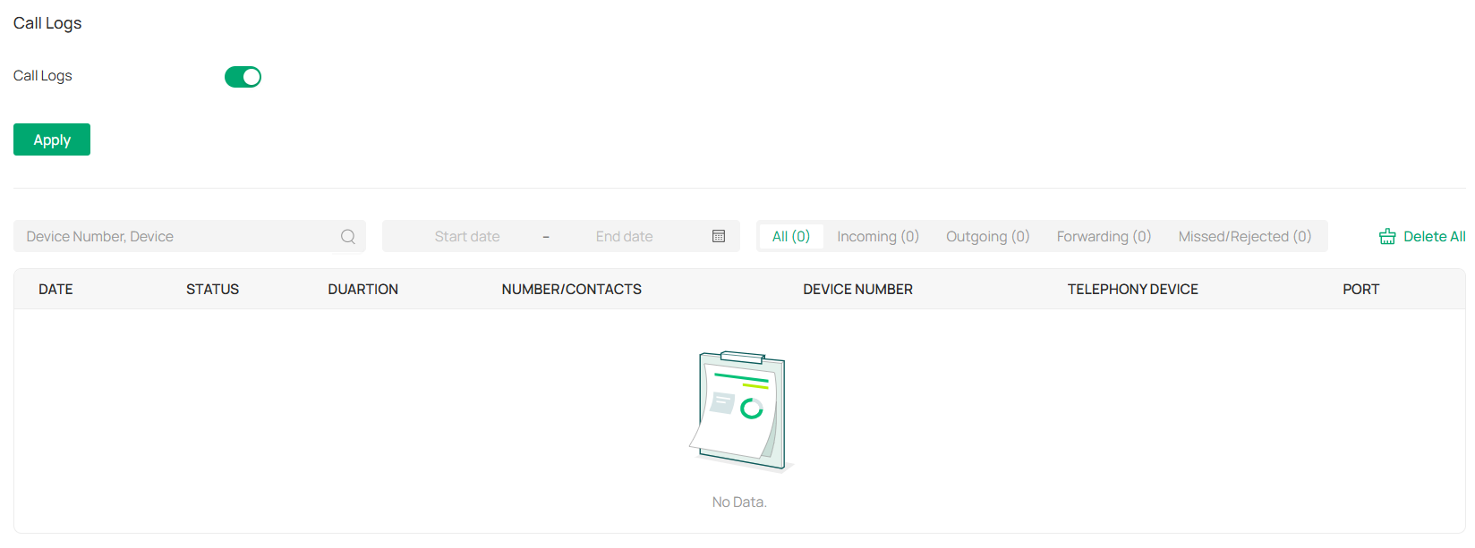
Advanced Settings
Overview
In Advanced Settings, you can configure Telephone Book,Emergency Number, DND (Do Not Disturb), and Call Forwarding.
Configuration
1. Launch the controller and access a site.
2. Go to Network Config > General Settings > VoIP > Advanced Settings.
3. Configure the functions according to actual site needs.
■ Telephone Book
In Telephone Book, you can save contact details and assign a speed dial number to the contact.
Click Create New Contact Person. Configure the parameters and click Create.
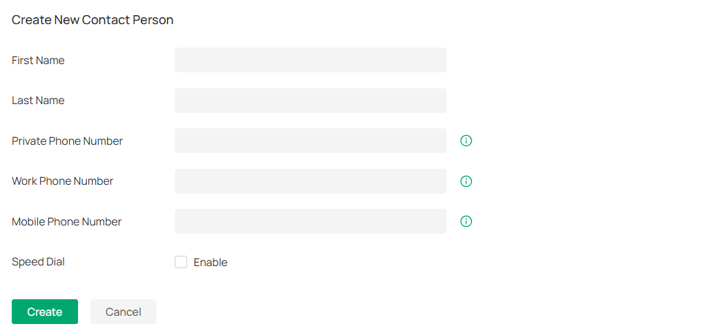
|
First Name / Last Name |
Enter the last name and first name of your contact. |
|---|---|
|
Private Phone Number |
Enter the private phone number of your contact. |
|
Work Phone Number |
Enter the work phone number of your contact. |
|
Mobile Phone Number |
Enter the mobile phone number of your contact. |
|
Speed Dial Number Type |
Select the type of number for speed dial. Speed Dial allows you to quickly place a call with fewer numbers to dial. |
|
Speed Dial Number |
Set the speed dial number. After saving the settings, you can simply press this number followed by # to place a call. |
■ Emergency Number Settings
Emergency number settings can be helpful to make a call for help when emergency occurs.
Enable Emergency Number. Configure the parameters and click Apply.
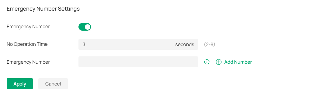
|
Emergency Number |
Enable this function to allow the telephony device to call a specific contact when the handset is picked up but no operation is done within a specific time period. |
|---|---|
|
No Operation Time |
Specify the time period before the telephony device makes a call automatically. |
|
Emergency Number |
Specify one or more phone numbers for emergency calls. The telephony device will call these numbers in order if the previous call is not answered. |
• DND (Do Not Disturb)
DND (Do Not Disturb) allows you to temporarily block all incoming calls based on your specific schedule.
Enable DND. Configure the parameters and click Apply.
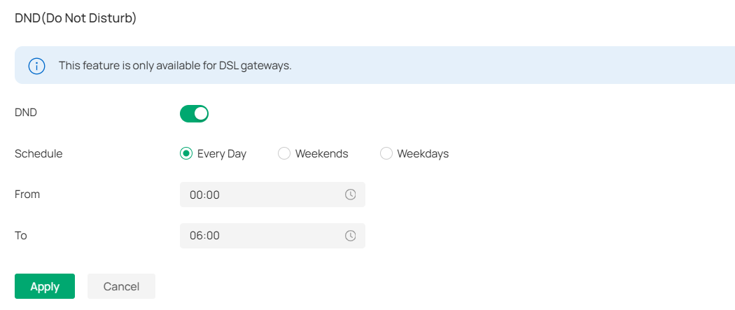
|
Schedule |
Specify the days you want to block the incoming calls. |
|---|---|
|
From / To |
Set the start time and end time of the DND period you want to block incoming calls. |
• Call Forwarding
Call Forwarding allows you to redirect incoming calls to a designated phone number.
Click Add New Call Forwarding. Enable the function, configure the parameters, and click Add.
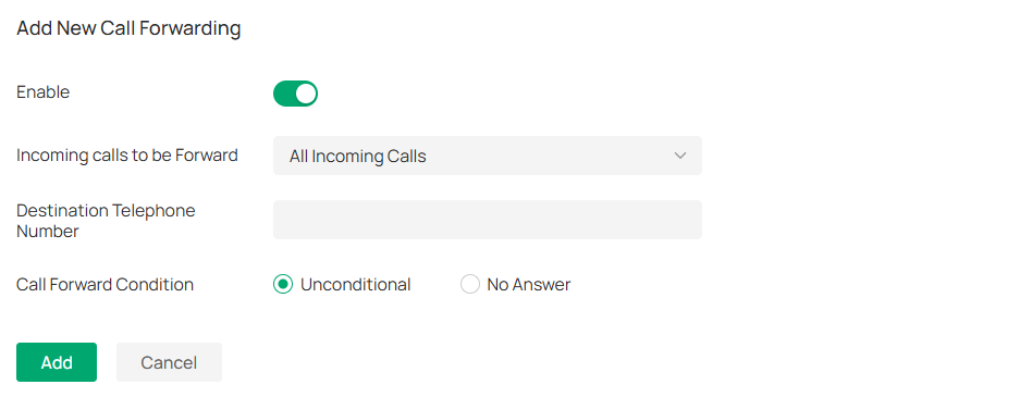
|
Incoming Calls to be Forwarded |
Select a call type to be forwarded. All Incoming Calls: If this option is selected, all incoming calls will be forwarded. Calls to the Telephone Number: If this option is selected, select a telephone number from the list. Any incoming calls to this number will be forwarded. Calls to the Phone: If this option is selected, select a telephony device from the list. Any incoming calls to this device will be forwarded. Calls from a Person in the Telephone Book: If this option is selected, select a contact from the list. Any incoming calls from this contact will be forwarded. Calls from the Telephone Number: If this option is selected, enter a specific telephone number. Any incoming calls from this number will be forwarded. |
|---|---|
|
Destination Telephone Number |
Enter a Destination Telephone Number that incoming calls will be redirected to. |
|
Call Forward Condition |
Select the Call Forward Condition. Unconditional: All incoming calls will be redirected to the designated telephone number whether the receiver is busy or not. No Answer: Incoming calls that are not answered for the specified time period will be redirected to the designated telephone number. |
• Voice Mail
Voice Mail allows callers to leave voice messages on an external USB storage device with the appropriate configuration files when calls are not answered. To use this function, plug the USB storage device into the USB port on the router. This feature is only available for DSL gateways.
Enable Voice Mail, configure the parameters, and click Apply. The voice mails will be recorded in the Voice Mail List.

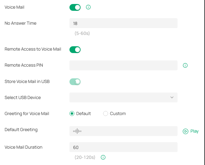
|
No Answer Time |
Enter the duration for the incoming calls to go to voicemail or the destination telephone number when there is no response. |
|---|---|
|
Remote Access to Voice Mail |
(Optional) If you want to listen to your voice mails remotely, enable Remote Access to Voice Mail. |
|
Remote Access PIN |
To access your voice mail remotely, dial the number for incoming calls. When your personal greeting starts, press *. Enter your Remote Access PIN when prompted. |
|
Store Voice Mail in USB |
Enable Store Voice Mail in USB. Select a path in the USB storage device to save your voice mail. |
|
Greeting for Voice Mail |
Select the Greeting for Voice Mail to use either the default or your custom greeting for the voice mail. You can click the Play icon to play the greeting. |
|
Default Greeting |
Click the Play icon to play the greeting. |
|
Voice Mail Duration |
Specify the length of each voice mail. |
Use CLI Configuration
CLI configuration is essentially to configure devices via command lines. It is a supplementary means of GUI configuration. CLI configuration may conflict with GUI configuration.
The Controller supports two types of CLI configuration: Site CLI and Device CLI.
■ Site CLI
Site CLI supports batch configuration of devices that support CLI configuration on the site.
■ Device CLI
Device CLI supports batch configuration of selected devices.
Currently, CLI configuration only supports switches. Please refer to the CLI Reference Guide of the correspond Omada switch to understand the CLI commands.
If you need to use CLI configuration, please read the precautions and User Guide carefully. You can contact TP-Link technical support if necessary.
After applying the CLI configuration, you can go to Devices > Application Result to view the configuration results.
General Precautions
1. The GUI and CLI configuration should be planned globally according to the actual network topology and requirements.
2. To avoid conflicts, it is recommended not to use the CLI to configure the existing functions of the GUI.
a. When adopting a new device, the Controller will apply configurations to the device in the order of GUI, Site CLI, and then Device CLI. If there is a configuration conflict, the configuration applied last takes effect.
b. CLI profiles (including Site CLI profiles and Device CLI profiles) will only be sent to devices once after applied, unless the “Apply Again” button in the Application Result is clicked to trigger the full configurations application.
c. When a device upgrades its firmware, the Controller will apply the full configurations to the device in the order of GUI, Site CLI, and then Device CLI.
d. Since the configurations applied later will overwrite the previous configurations, the configuration results of different devices may be different after the same function has been modified repeatedly via GUI, Site CLI and Device CLI.
3. The Controller will not verify the existing GUI and CLI configurations of devices. Be sure to check the existing configurations before performing new configurations. Otherwise, unexpected results may occur after the configurations are applied, and the devices may even go offline.
4. To avoid configuration conflicts, if you really need to use the CLI to configure a certain function, it is recommended not to configure it via GUI at the same time.
5. To avoid disconnection of devices from the Controller due to configuration errors or conflicts, it is recommended to configure VLAN, VLAN Interface, IP Address, ACL, etc. via GUI, and avoid modifying related configurations via CLI.
Repeated Configurations
When the same function is configured via CLI multiple times, the previous configuration may be overwritten, and the last configuration shall prevail.
a. It is recommended to confirm the currently effective commands via the CLI configuration viewing function “Show Running Config”.
b. If you need to cancel a certain configuration, use the “no” command.
c. If you need to modify a certain configuration, you can enter a new command to overwrite the configuration.
d. Apply the final configuration, and confirm that the function is configured correctly and takes effect via the CLI configuration viewing function.
Execution Failures
If a CLI command fails to be executed, an error will be reported and subsequent commands will be executed. You can view the error details via the error message, and the commands that have been successfully executed before will not be undone. It is recommended to follow the steps below:
a. Use the CLI configuration viewing function (Show Running Config) to confirm the commands that have taken effect. If you need to cancel them, you can enter “no” commands and apply them to devices.
b. Troubleshoot and correct the command error, regenerate the CLI configuration, and apply it to devices.
Command Modification
If you need to modify the commands issued via CLI, please follow the steps below:
a. Use the CLI configuration view function (Show Running Config) to confirm the commands that have taken effect, and sort out the commands that need to be canceled.
b. Enter “no” commands to cancel the configurations, and apply them to devices.
Prohibited Commands
1. CLI commands such as modifying user name and password, managing VLAN, SDM profile, reboot, reset, upgrade, import and export configurations have been prohibited. When using other CLI commands, please also pay attention to avoid affecting the management of the Controller.
2. Device CLI supports the variable function. The variable content does not have too many restrictions, for example, you can enter CLI commands, but it is not recommended to use it in this way.
Site CLI
Overview
Site CLI enables batch configurations of all devices that support CLI configuration on the site via command lines.
Configuration
1. Go to Network Config > General Settings > CLI Configuration > Site CLI.
2. Click Create New Site CLI Profile and create a CLI profile according to your needs.

Note:
• The # character is a special command, which indicates entering the configure mode. Please use it in a separate line. If you add other commands after it in the same line, they will be ignored.
• If a command starts with the ! character, the command will be ignored.
|
Name |
Specify the name of the CLI profile. |
|---|---|
|
Description |
(Optional) Enter a description for identification. |
|
CLI |
Enter the command lines manually. |
|
Import CLI from Device |
Click and select a device that supports CLI configuration to import its running config. |
|
Import CLI from File |
Click and select an existing command file to import command lines. |
3. Click Save to add the profile. The new profile is in inactive state and will not be applied to devices.
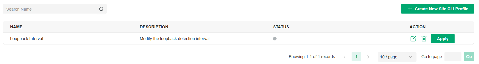
4. Click Apply to apply the CLI. The profile will change to active state and apply configurations to all devices that support CLI configuration on the site.
Note:
Once the profile becomes active, you will be unable to edit it.
To check whether the profile is successfully applied to devices and takes effect, click View CLI Details to view the configuration results on the Devices > Application Result page.
Note:
Deleting a CLI profile will not take effect on existing configurations on devices. To delete the configurations, use the “no” command.
Device CLI
Overview
Device CLI enables batch configuration of specific devices via command lines.
Device CLI supports variables. You can use the %x% format to define a variable x, and then set different values for different switches. When the Controller applies the Device CLI configuration to switches, it will automatically modify the variable %x% to the values you set.
Configuration
1. Go to Network Config > General Settings > CLI Configuration > Device CLI. Click Create New Device CLI Profile and create a CLI profile according to your needs.
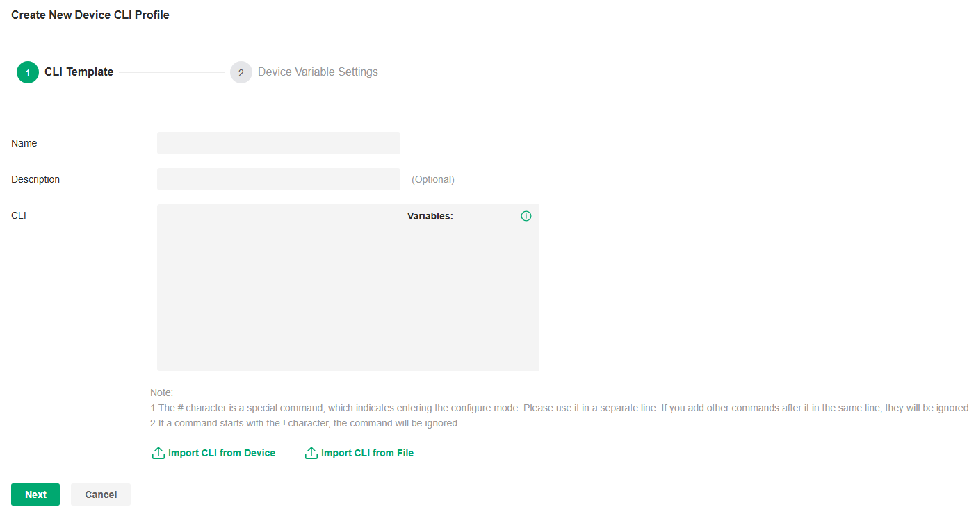
Note:
• The # character is a special command, which indicates entering the configure mode. Please use it in a separate line. If you add other commands after it in the same line, they will be ignored.
• If a command starts with the ! character, the command will be ignored.
|
Name |
Specify the name of the CLI profile. |
|---|---|
|
Description |
(Optional) Enter a description for identification. |
|
CLI |
Enter the command lines manually. You can enter %xxx% in the CLI template to define variables. |
|
Import CLI from Device |
Click and select a device that supports CLI configuration to import its running config. |
|
Import CLI from File |
Click and select an existing command file to import command lines. |
2. Click Next. Select the devices to apply the CLI profile.

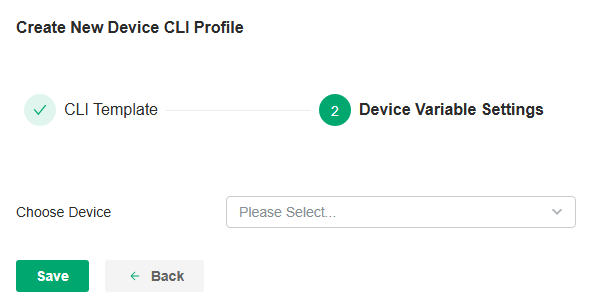
3. Click Save to add the profile. The new profile is in inactive state and will not be applied to devices.
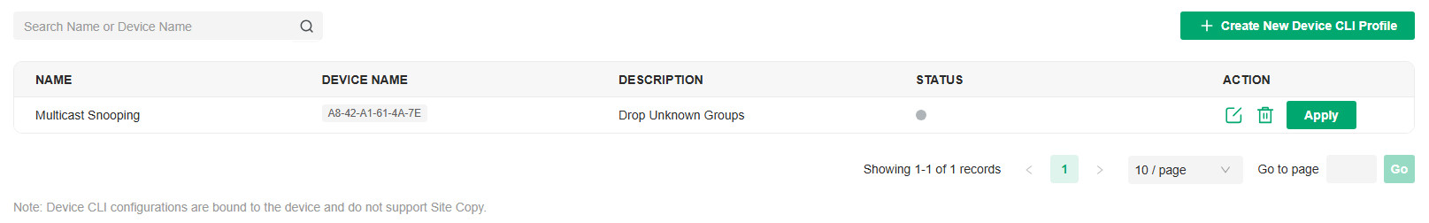
4. Click Apply to apply the CLI. The profile will change to active state and apply configurations to the devices you selected.
Note:
Once the profile becomes active, you will be unable to edit it.
To check whether the profile is successfully applied to devices and takes effect, click View CLI Details to view the configuration results on the Devices > Application Result page.
Note:
Deleting a CLI profile will not take effect on existing configurations on devices. To delete the configurations, use the “no” command.
Configuring Wired Networks
This chapter guides you on how to configure wired networks with the Omada Controller.
Overview
Wired networks enable your wired devices and clients including the gateway, switches, APs and PCs to connect to each other and to the internet.
As shown in the following figure, wired networks consist of two parts: Internet and LAN.
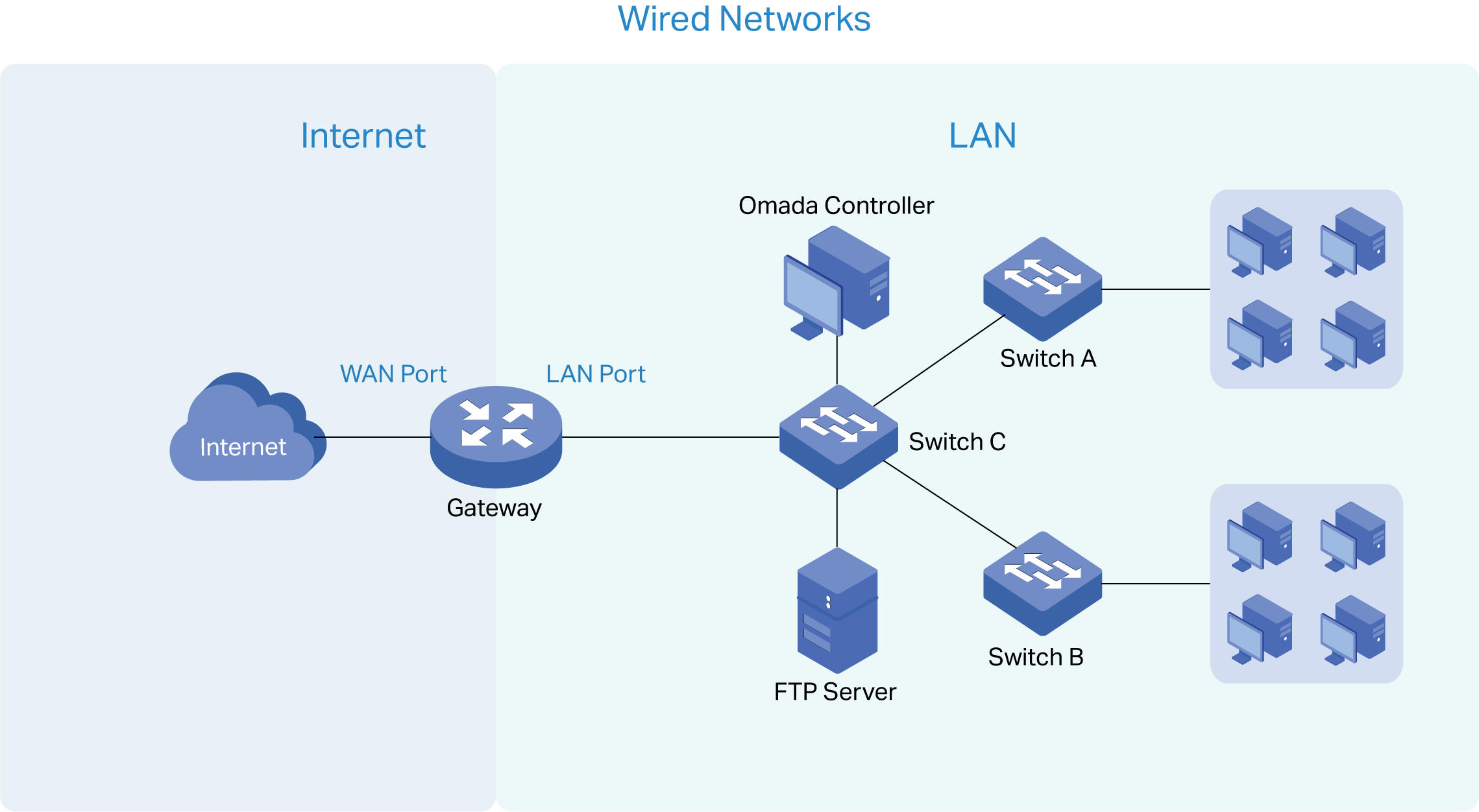

For Internet, you determine the number of WAN ports on the gateway and how they connect to the internet. You can set up an IPv4 connection and IPv6 connection to your internet service provider (ISP) according to your needs. The parameters of the internet connection for the gateway depend on which connection types you use. For an IPv4 connection, the following internet connection types are available: Dynamic IP, Static IP, PPPoE, L2TP, and PPTP. For an IPv6 connection, the following internet connection types are available: Dynamic IP (SLAAC/ DHCPv6), Static IP, PPPoE, 6to4 Tunnel, and Pass-Through (Bridge). And, when more than one WAN port is configured, you can configure Load Balancing to optimize the resource utilization if needed.
For LAN, you configure the wired internal network and how your devices logically separate from or connect to each other by means of VLANs and interfaces. Advanced LAN features include IGMP Snooping, DHCP Server and DHCP Options, PoE, Voice Network, 802.1X Control, Port Isolation, Spanning Tree, LLDP-MED, and Bandwidth Control.
Set Up an Internet Connection
Configuration
To set up an internet connection, follow these steps:
1)Configure the number of WAN ports on the gateway based on needs.
2) Configure WAN Connections. You can set up the IPv4 connection, IPv6 connection, or both.
3)(Optional) Configure Load Balancing if more than one WAN port is configured.
Step 1: Select WAN Mode
Launch the controller and access a site. Go to Network Config > Network Settings > Internet to load the following page. In the WAN Mode section, configure the number of WAN ports deployed by the gateway and other parameters. Then click Apply.
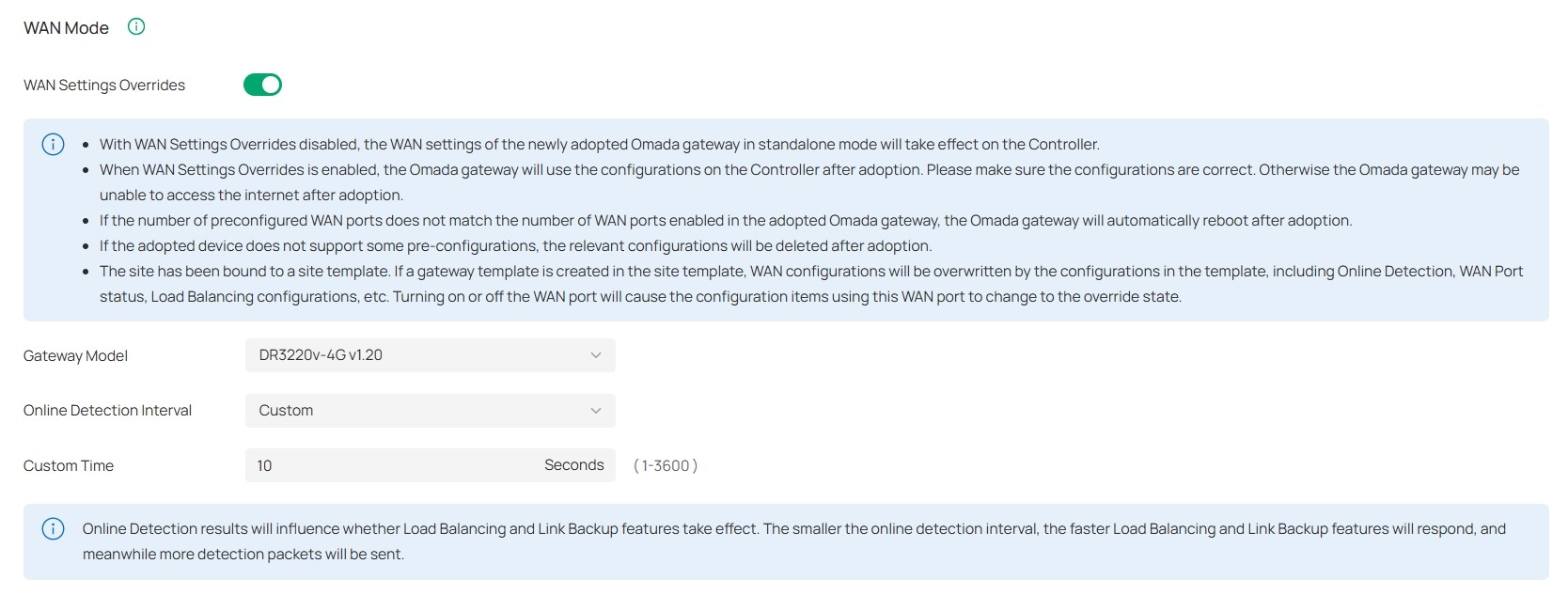
|
WAN Settings Overrides |
With this option disabled, the WAN settings of the newly adopted Omada gateway in standalone mode will take effect on the controller. When this option is turned on, the gateway will use the configurations on the Controller after adoption. Please make sure the configurations are correct. Otherwise the gateway may be unable to access the internet after adoption. If the adopted device does not support some pre-configurations, the relevant configurations will be deleted after adoption. |
|---|---|
|
Gateway Model |
Specify the gateway model and version. If you change the gateway, follow the web instructions to select WAN ports and copy WAN port settings. If the number of preconfigured WAN ports does not match the number of WAN ports enabled in the adopted Omada gateway, the gateway will automatically reboot after adoption. |
|
Online Detection Interval |
Select how often the WAN ports detect WAN connection status. If you don’t want to enable online detection, select Disable. Online Detection results will influence whether Load Balancing and Link Backup features take effect. The smaller the online detection interval, the faster Load Balancing and Link Backup features will respond, and meanwhile more detection packets will be sent. |
Step 2: Configure WAN Connections
Note: The number of configurable WAN ports is decided by WAN Mode.
■ Set Up DSL WAN Connection
Launch the controller and access a site. Go to Network Config > Network Settings > Internet. In the WAN Ports Config section, click the edit icon of USB Modem and configure the parameters.
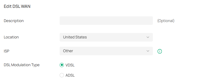
|
Description |
Enter a description for identification. |
|---|---|
|
Location |
Select your location. |
|
ISP |
Select your ISP (internet service provider). |
|
DSL Modulation Type |
Select the modulation type for your DSL connection. |
■ Set Up USB Modem Connection
Launch the controller and access a site. Go to Network Config > Network Settings > Internet. In the WAN Ports Config section, click the edit icon of USB Modem and configure the parameters.
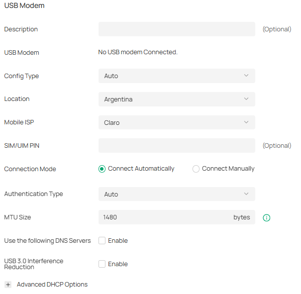
|
Description |
Enter a description for identification. |
|---|---|
|
USB Modem |
Display whether a USB modem is connected to the device and the name of the connected USB modem. |
|
Config Type |
Select a configuration type for the USB modem. Auto: Use the Location and Mobile ISP information below for configuration. Manually: Enter the Dial Number, APN, Username, and password provided by your Mobile ISP. |
|
Location |
Select your location. |
|
Mobile ISP |
Select your mobile ISP. |
|
SIM/UIM PIN |
(Optional) Enter the PIN of your SIM card. The field is required when the following information appears in the Message: PIN protection is enabled and the PIN is invalid. |
|
Connection Mode |
Select the connection mode. Connect Automatically: The router will use the USB modem to connect to the internet automatically. Connect Manually: You need to turn on/off the internet manually for the gateway on the device page. |
|
Authentication Mode |
Select the Authentication mode for the USB modem. The default value is Auto, and it is recommended to keep the default value. |
|
MTU Size |
Specify the MTU (Maximum Transmission Unit) of the USB WAN port. The default value is 1480, and it is recommended to keep the default value. MTU is the maximum data unit transmitted in the physical network. |
|
Use the following DNS Servers |
Enable the feature if you want to specify the Primary and Secondary DNS servers manually. |
|
USB 3.0 Interference Reduction |
Enable this option if you want to lower the data transfer speed of a USB 3.0 port to improve performance on the 2.4GHz Wi-Fi band. Enabling the feature trades USB 3.0 speed for better wireless stability. |
■ Set Up IPv4 Connection
Launch the controller and access a site. Go to Network Config > Network Settings > Internet. In the WAN Ports Config section, click the edit icon of a WAN port and configure the Connection Type according to the service provided by your ISP.
|
Connection Type |
Dynamic IP: If your ISP automatically assigns the IP address and the corresponding parameters, choose Dynamic IP. Static IP: If your ISP provides you with a fixed IP address and the corresponding parameters, choose Static IP. PPPoE: If your ISP provides you with a PPPoE account, choose PPPoE. L2TP: If your ISP provides you with an L2TP account, choose L2TP. PPTP: If your ISP provides you with a PPTP account, choose PPTP. |
|---|
· Dynamic IP
Choose Connection Type as Dynamic IP and configure the parameters.
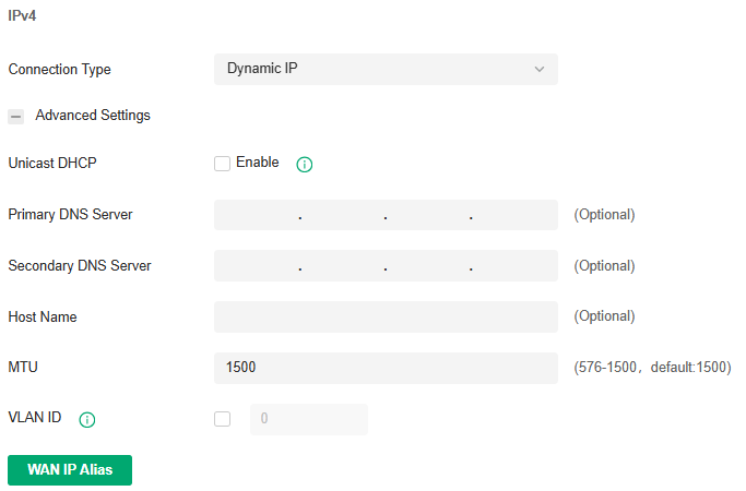
|
Unicast DHCP |
With this option enabled, the gateway will require the DHCP server to assign the IP address by sending unicast DHCP packets. Usually you need not to enable the option. |
|---|---|
|
Primary DNS Server / Secondary DNS Server |
Enter the IP address of the DNS server provided by your ISP if there is any. |
|
Host Name |
Enter a name for the gateway. |
|
MTU |
Specify the MTU (Maximum Transmission Unit) of the WAN port. MTU is the maximum data unit transmitted in the physical network. When the connection type is Dynamic IP, MTU can be set in the range of 576-1500 bytes. The default value is 1500. |
|
VLAN ID |
Add the WAN port to a VLAN and you need to specify the VLAN ID. Generally, you don’t need to manually configure it unless required by your ISP. |
|
VLAN Priority |
Priority is only available when Internet VLAN is enabled. The VLAN Priority function helps to prioritize the internet traffic based on your needs. You can determine the priority level for the traffic by specifying the tag. The tag ranges from 0 to 7. None means the packet will be forwarded without any operation. |
|
WAN IP Alias |
WAN IP Alias supports configuring multiple IP addresses on one WAN port, and these IP addresses can be used to configure virtual server and other functions. |
· Static IP
Choose Connection Type as Static IP and configure the parameters.
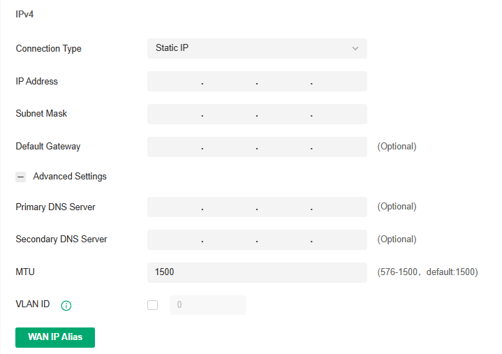
|
IP Address |
Enter the IP address provided by your ISP. |
|
Subnet Mask |
Enter the subnet mask provided by your ISP. |
|
Default Gateway |
Enter the default gateway provided by your ISP. |
|
Primary DNS Server / Secondary DNS Server |
Enter the IP address of the DNS server provided by your ISP if there is any. |
|
MTU |
Specify the MTU (Maximum Transmission Unit) of the WAN port. MTU is the maximum data unit transmitted in the physical network. When the connection type is Static IP, MTU can be set in the range of 576-1500 bytes. The default value is 1500. |
|
VLAN ID |
Add the WAN port to a VLAN and you need to specify the VLAN ID. Generally, you don’t need to manually configure it unless required by your ISP. |
|
VLAN Priority |
Priority is only available when Internet VLAN is enabled. The VLAN Priority function helps to prioritize the internet traffic based on your needs. You can determine the priority level for the traffic by specifying the tag. The tag ranges from 0 to 7. None means the packet will be forwarded without any operation. |
|
WAN IP Alias |
WAN IP Alias supports configuring multiple IP addresses on one WAN port, and these IP addresses can be used to configure virtual server and other functions. |
· PPPoE
Choose Connection Type as PPPoE and configure the parameters.

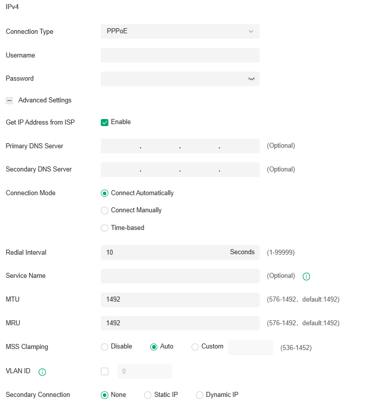
|
Username |
Enter the PPPoE username provided by your ISP. |
|---|---|
|
Password |
Enter the PPPoE password provided by your ISP. |
|
Get IP address from ISP |
With this option enabled, the gateway gets IP address from ISP when setting up the WAN connection. With this option disabled, you need to specify the IP Address provided by your ISP. |
|
Primary DNS Server / Secondary DNS Server |
Enter the IP address of the DNS server provided by your ISP if there is any. |
|
Connection Mode |
Connect Automatically: The gateway activates the connection automatically when the connection is down. You need to specify the Redial Interval, which decides how often the gateway tries to redial after the connection is down. Connect Manually: You can manually activate or terminate the connection. Time-Based: During the specified period, the gateway will automatically activate the connection. You need to specify the Time Range when the connection is up. |
|
Redial Interval |
Specify how often the gateway tries to redial after the connection is down. |
|
Service Name |
Keep it blank unless your ISP requires you to configure it. |
|
MTU |
Specify the MTU (Maximum Transmission Unit) of the WAN port. MTU is the maximum data unit transmitted in the physical network. When the connection type is PPPoE, MTU can be set in the range of 576-1492 bytes. The default value is 1492. |
|
MRU |
Specify the MRU (Maximum Receive Unit) of the WAN port. MRU is the maximum data unit transmitted in the Data link layer. |
|
MSS Clamping |
Specify the upper limit of the value of the MSS (Maximum Segment Size) field negotiated by the sending and receiving parties when establishing TCP connection to avoid IP fragmentation. If the value of the MSS field negotiated by the communication parties exceeds the specified value, the gateway will change the negotiated MSS field to the specified value Disabled: Disable the MSS Clamping function, and the gateway will not intervene in the MSS value negotiated by the communication parties. Auto: Automatically calculate MSS value based on path MTU. Custom: Select this option to specify the MSS value. It should not exceed the MTU value. |
|
VLAN ID |
Add the WAN port to a VLAN and you need to specify the VLAN ID. Generally, you don’t need to manually configure it unless required by your ISP. |
|
VLAN Priority |
Priority is only available when Internet VLAN is enabled. The VLAN Priority function helps to prioritize the internet traffic based on your needs. You can determine the priority level for the traffic by specifying the tag. The tag ranges from 0 to 7. None means the packet will be forwarded without any operation. |
|
Secondary Connection |
Secondary connection is required by some ISPs. Select the connection type required by your ISP. None: Select this if the secondary connection is not required by your ISP. Static IP: Select this if your ISP provides you with a fixed IP address and subnet mask for the secondary connection. You need to specify the IP Address and Subnet Mask provided by your ISP. Dynamic IP: Select this if your ISP automatically assigns the IP address and subnet mask for the secondary connection. |
· L2TP
Choose Connection Type as L2TP and configure the parameters.
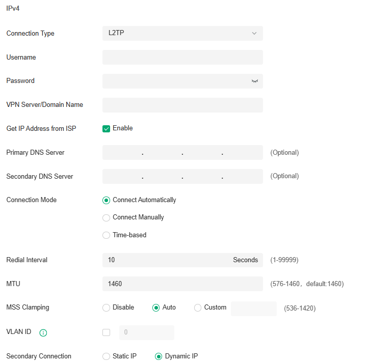
|
Username |
Enter the L2TP username provided by your ISP. |
|---|---|
|
Password |
Enter the L2TP password provided by your ISP. |
|
VPN Server / Domain Name |
Enter the VPN Server/Domain Name provided by your ISP. |
|
Get IP address from ISP |
With this option enabled, the gateway gets IP address from ISP when setting up the WAN connection. With this option disabled, you need to specify the IP address provided by your ISP. |
|
Primary DNS Server / Secondary DNS Server |
Enter the IP address of the DNS server provided by your ISP if there is any. |
|
Connection Mode |
Connect Automatically: The gateway activates the connection automatically when the connection is down. You need to specify the Redial Interval, which decides how often the gateway tries to redial after the connection is down. Connect Manually: You can manually activate or terminate the connection. Time-Based: During the specified period, the gateway will automatically activate the connection. You need to specify the Time Range when the connection is up. |
|
Redial Interval |
Specify how often the gateway tries to redial after the connection is down. |
|
MTU |
Specify the MTU (Maximum Transmission Unit) of the WAN port. MTU is the maximum data unit transmitted in the physical network. When the connection type is L2TP, MTU can be set in the range of 576-1460 bytes. The default value is 1460. |
|
MSS Clamping |
Specify the upper limit of the value of the MSS (Maximum Segment Size) field negotiated by the sending and receiving parties when establishing TCP connection to avoid IP fragmentation. If the value of the MSS field negotiated by the communication parties exceeds the specified value, the gateway will change the negotiated MSS field to the specified value Disabled: Disable the MSS Clamping function, and the gateway will not intervene in the MSS value negotiated by the communication parties. Auto: Automatically calculate MSS value based on path MTU. Custom: Select this option to specify the MSS value. It should not exceed the MTU value. |
|
VLAN ID |
Add the WAN port to a VLAN and you need to specify the VLAN ID. Generally, you don’t need to manually configure it unless required by your ISP. |
|
VLAN Priority |
Priority is only available when Internet VLAN is enabled. The VLAN Priority function helps to prioritize the internet traffic based on your needs. You can determine the priority level for the traffic by specifying the tag. The tag ranges from 0 to 7. None means the packet will be forwarded without any operation. |
|
Secondary Connection |
Select the connection type required by your ISP. Static IP: Select this if your ISP provides you with a fixed IP address and subnet mask for the secondary connection. You need to specify the IP Address, Subnet Mask, Default Gateway (Optional), Primary DNS Server (Optional), and Secondary DNS Server (Optional) provided by your ISP. Dynamic IP: Select this if your ISP automatically assigns the IP address and subnet mask for the secondary connection. |
· PPTP
Choose Connection Type as PPTP and configure the parameters.
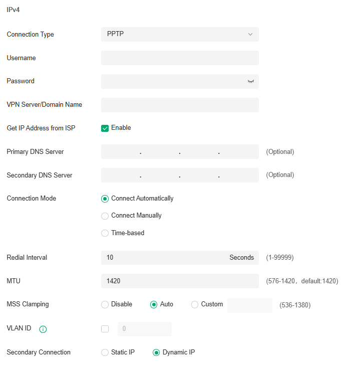
|
Username |
Enter the PPTP username provided by your ISP. |
|---|---|
|
Password |
Enter the PPTP password provided by your ISP. |
|
VPN Server / Domain Name |
Enter the VPN Server/Domain Name provided by your ISP. |
|
Get IP address from ISP |
With this option enabled, the gateway gets IP address from ISP when setting up the WAN connection. With this option disabled, you need to specify the IP address provided by your ISP. |
|
Primary DNS Server / Secondary DNS Server |
Enter the IP address of the DNS server provided by your ISP if there is any. |
|
Connection Mode |
Connect Automatically: The gateway activates the connection automatically when the connection is down. You need to specify the Redial Interval, which decides how often the gateway tries to redial after the connection is down. Connect Manually: You can manually activate or terminate the connection. Time-Based: During the specified period, the gateway will automatically activate the connection. You need to specify the Time Range when the connection is up. |
|
Redial Interval |
Specify how often the gateway tries to redial after the connection is down. |
|
MTU |
Specify the MTU (Maximum Transmission Unit) of the WAN port. MTU is the maximum data unit transmitted in the physical network. When the connection type is PPTP, MTU can be set in the range of 576-1420 bytes. The default value is 1420. |
|
MSS Clamping |
Specify the upper limit of the value of the MSS (Maximum Segment Size) field negotiated by the sending and receiving parties when establishing TCP connection to avoid IP fragmentation. If the value of the MSS field negotiated by the communication parties exceeds the specified value, the gateway will change the negotiated MSS field to the specified value Disabled: Disable the MSS Clamping function, and the gateway will not intervene in the MSS value negotiated by the communication parties. Auto: Automatically calculate MSS value based on path MTU. Custom: Select this option to specify the MSS value. It should not exceed the MTU value. |
|
VLAN ID |
Add the WAN port to a VLAN and you need to specify the VLAN ID. Generally, you don’t need to manually configure it unless required by your ISP. |
|
VLAN Priority |
Priority is only available when Internet VLAN is enabled. The VLAN Priority function helps to prioritize the internet traffic based on your needs. You can determine the priority level for the traffic by specifying the tag. The tag ranges from 0 to 7. None means the packet will be forwarded without any operation. |
|
Secondary Connection |
Select the connection type required by your ISP. Static IP: Select this if your ISP provides you with a fixed IP address and subnet mask for the secondary connection. You need to specify the IP Address, Subnet Mask, Default Gateway (Optional), Primary DNS Server (Optional), and Secondary DNS Server (Optional) provided by your ISP. Dynamic IP: Select this if your ISP automatically assigns the IP address and subnet mask for the secondary connection. |
■ Set Up IPv6 Connection
For IPv6 connections, check the box to enable the IPv6 connection, select the internet connection type according to the requirements of your ISP.
|
Connection Type |
Dynamic IP (SLAAC/DHCPv6): If your ISP uses Dynamic IPv6 address assignment, either DHCPv6 or SLAAC+Stateless DHCP, select Dynamic IP (SLAAC/DHCPv6). Static IP: If your ISP provides you with a fixed IPv6 address, select Static IP. PPPoE: If your ISP uses PPPoEv6, and provides a username and password, select PPPoE. 6to4 Tunnel: If your ISP uses 6to4 deployment for assigning IPv6 address, select 6to4 Tunnel. 6to4 is an internet transition mechanism for migrating from IPv4 to IPv6, a system that allows IPv6 packets to be transmitted over an IPv4 network. The IPv6 packet will be encapsulated in the IPv4 packet and transmitted to the IPv6 destination through IPv4 network. Pass-Through (Bridge): In Pass-Through (Bridge) mode, the gateway works as a transparent bridge. The IPv6 packets received from the WAN port will be transparently forwarded to the LAN port and vice versa. No extra parameter is required. |
|---|
· Dynamic IP (SLAAC/DHCPv6)
Choose Connection Type as Dynamic IP (SLAAC/DHCPv6) and configure the parameters.
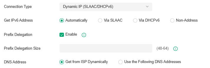
|
Get IPv6 Address |
Select the proper method whereby your ISP assigns IPv6 address to your gateway. Automatically: With this option selected, the gateway will automatically select SLAAC or DHCPv6 to get IPv6 addresses. Via SLAAC: With SLAAC (Stateless Address Auto-Configuration) selected, your ISP assigns the IPv6 address prefix to the gateway and the gateway automatically generates its own IPv6 address. Also, your ISP assigns other parameters including the DNS server address to the gateway. Via DHCPv6: With DHCPv6 selected, your ISP assigns an IPv6 address and other parameters including the DNS server address to the gateway using DHCPv6. Non-Address: With this option selected, the gateway will not get an IPv6 address. |
|---|---|
|
Prefix Delegation |
Select Enable to get an address prefix by DHCPv6 server from your ISP, or Disable to designate an address prefix for your LAN port manually. Clients in LAN will get an IPv6 address with this prefix. |
|
Prefix Delegation Size |
With Prefix Delegation enabled, enter the Prefix Delegation Size to determine the length of the address prefix. If you are not sure about the value, you can ask your ISP. |
|
DNS Address |
Select whether to get the DNS address dynamically from your ISP or designate the DNS address manually. Get from ISP Dynamically: The DNS address will be automatically assigned by the ISP. Use the Following DNS Addresses: Enter the DNS address provided by the ISP. |
· Static IP
Choose Connection Type as Static IP and configure the parameters.
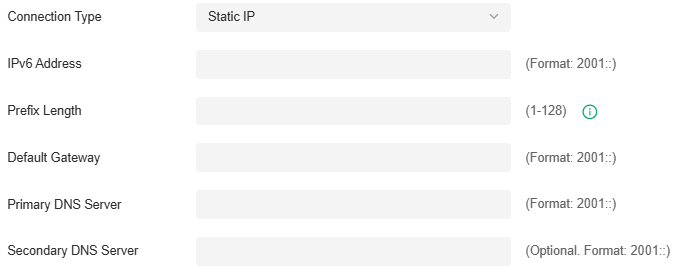
|
IPv6 Address |
Enter the static IPv6 address information received from your ISP. |
|---|---|
|
Prefix Length |
Enter the prefix length of the IPv6 address received from your ISP. |
|
Default Gateway |
Enter the default gateway provided by your ISP. |
|
Primary DNS Server |
Enter the IP address of the primary DNS server provided by your ISP. |
|
Secondary DNS Server |
(Optional) Enter the IP address of the secondary DNS server, which provides redundancy in case the primary DNS server goes down. |
· PPPoE
Choose Connection Type as PPPoE and configure the following parameters. Then click Apply.
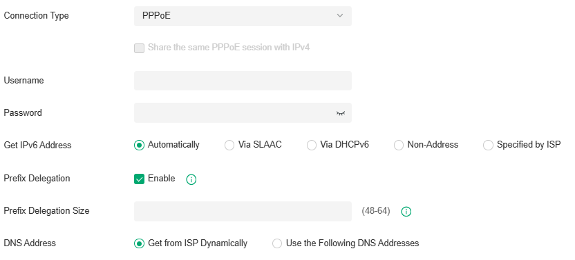
|
Share the same PPPoE session with IPv4 |
If your ISP provides only one PPPoE account for both IPv4 and IPv6 connections, and you have already established an IPv4 connection on this WAN port, you can check the box, then the WAN port will use the PPP session of IPv4 PPPoE connection to get the IPv6 address. In this case, you do not need to enter the username and password of the PPPoE account. If your ISP provides two separate PPPoE accounts for the IPv4 and IPv6 connections, or the IPv4 connection of this WAN port is not based on PPPoE, do not check the box and manually enter the username and password for the IPv6 connection. |
|---|---|
|
Username |
Enter the username of your PPPoE account provided by your ISP. |
|
Password |
Enter the password of your PPPoE account provided by your ISP. |
|
Get IPv6 Address |
Select the proper method whereby your ISP assigns IPv6 address to your gateway. Automatically: With this option selected, the gateway will automatically select the method to get IPv6 addresses between SLAAC and DHCPv6. Via SLAAC: With SLAAC (Stateless Address Auto-Configuration) selected, your ISP assigns the IPv6 address prefix to the gateway and the gateway automatically generates its own IPv6 address. Also, your ISP assigns other parameters including the DNS server address to the gateway. Via DHCPv6: With DHCPv6 selected, your ISP assigns an IPv6 address and other parameters including the DNS server address to the gateway using DHCPv6. Non-Address: With this option selected, the gateway will not get an IPv6 address. Specified by ISP: With this option selected, enter the IPv6 address you get from your ISP. |
|
Prefix Delegation |
Select Enable to get an address prefix by DHCPv6 server from your ISP, or Disable to designate an address prefix for your LAN port manually. Clients in LAN will get an IPv6 address with this prefix. |
|
Prefix Delegation Size |
With Prefix Delegation enabled, enter the Prefix Delegation Size to determine the length of the address prefix. If you are not sure about the value, you can ask your ISP. |
|
DNS Address |
Select whether to get the DNS address dynamically from your ISP or designate the DNS address manually. Get from ISP Dynamically: The DNS address will be automatically assigned by the ISP. Use the Following DNS Addresses: Enter the DNS address provided by the ISP. |
· 6to4 Tunnel
Choose Connection Type as 6to4 Tunnel and configure the parameters.
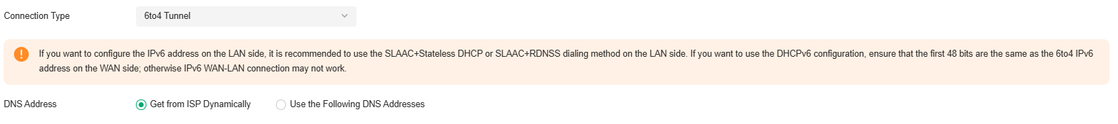
|
DNS Address |
Select whether to get the DNS address dynamically from your ISP or designate the DNS address manually. Get from ISP Dynamically: The DNS address will be automatically assigned by the ISP. Use the Following DNS Addresses: Enter the DNS address provided by the ISP. |
|---|
· Pass-Through (Bridge)
Choose Connection Type as Pass-Through (Bridge) and no configuration is required for this type of connection.
_20251225021419v.PNG)
■ Set Up MAC Address
Launch the controller and access a site. Go to Network Config > Network Settings > Internet. In the WAN Ports Config section, click the edit icon of a WAN port and configure the MAC address according to actual needs.
|
MAC Address |
Use Default MAC Address: The WAN port uses the default MAC address to set up the internet connection. It’s recommended to use the default MAC address unless required otherwise. Customize MAC Address: The WAN port uses a customized MAC address to set up the internet connection and you need to specify the MAC address. Typically, this is required when your ISP bound the MAC address with your account or IP address. If you are not sure, contact the ISP. |
|---|
Step 3: (Optional) Configure Load Balancing
Note: Loading Balancing is only available when you configure more than one WAN port.
Launch the controller and access a site. Go to Network Config > Network Settings > Internet. In Load Balancing, configure the following parameters and click Apply.
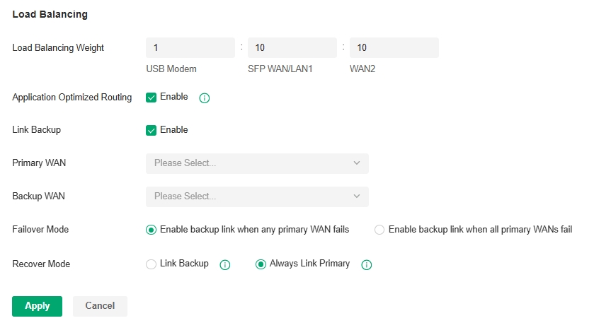
|
Load Balancing Weight |
Specify the ratio of network traffic that each WAN port carries. |
|---|---|
|
Application Optimized Routing |
With Application Optimized Routing enabled, the router will consider the source IP address and destination IP address (or destination port) of the packets as a whole and record the WAN port they pass through. Then the packets with the same source IP address and destination IP address ( or destination port) will be forwarded to the recorded WAN port. This feature ensures that multi-connected applications work properly. |
|
Link Backup |
With Link Backup enabled, the router will switch all the new sessions from dropped lines automatically to another to keep an always on-line network. |
|
Backup WAN / Primary WAN |
The backup WAN port backs up the traffic for the primary WAN ports under the specified condition. |
|
Failover Mode |
Select whether to enable backup link when any primary WAN fails or all primary WANs fail. |
|
Recover Mode |
Link Backup: The system will switch all the new sessions from dropped line automatically to another to keep an always on-link network. Always Link Primary: Traffic is always forwarded through the primary WAN port unless it fails. The system will try to forward the traffic via the backup WAN port when it fails, and switch back when it recovers. |
Configure LAN Networks
Overview
The LAN page allows you to configure wired internal network. Based on 802.1Q VLAN, Omada Controller provides a convenient and flexible way to separate and deploy the network. The network can be logically segmented by departments, application,or types of users, without regard to geographic locations.
Guidelines
To create a LAN, follow the guidelines:
1) Create a new Network with specific purpose. Select the device to serve as the DHCP Server based on the purpose of the VLAN, configure the VLAN on the selected device, specify the VLAN ID, and set related network parameters.
2) Bind the VLAN to the destination device port according to the actual use scenario. It can flexibly divide the network logic boundary to meet different business requirements.
3) Confirm the configuration and apply to activate the VLAN.
4) View the devices that are currently functioning in this VLAN through the topology view or check the configuration of this VLAN on the device ports through the port view.
Configuration
Now you can view the devices that are currently functioning in this VLAN through the topology view or check the configuration of this VLAN on the device ports through the port view.
1. Launch the controller and access a site.
2. Go to Network Config > Network Settings > LAN. Click Add to create a network.
3. Set the network name and VLAN type.
|
Name |
Enter a name to identify the network. |
|---|---|
|
VLAN Type |
Specify whether to use a single VLAN or multiple VLANs. If the VLAN Type is “Multiple” and the DHCP Server Device Type is “Gateway”, a single network containing multiple VLAN IDs will be created. If the VLAN Type is “Multiple” and the DHCP Server Device Type is “External Device” or “None”, multiple networks will be created, each corresponding to one VLAN. |
4. Select the DHCP Server Device type for the network. Parameters to configured will vary by device type.
· If you select a gateway, configure the following parameters:
|
VLAN |
Enter a VLAN ID with the value between 1 and 4090. Each VLAN can be uniquely identified by its VLAN ID, which is transmitted and received as IEEE 802.1Q tag in an Ethernet frame. |
|---|---|
|
Gateway/Subnet |
Enter the IP address and subnet mask in the CIDR format. The CIDR Notation here includes the IP address and subnet mask of the default gateway.The summary of the information that you entered will show up below in realtime. |
|
DHCP Server |
Click the checkbox to allow the device to serve as the DHCP server for this network. A DHCP server assigns IP addresses, DNS server, default gateway, and other parameters to all devices in the network. Deselect the box if there is already a DHCP server in the network. If selected, set the starting and ending IP addresses of the DHCP address pool in the fields provided. |
You can expand and configure Advanced Settings if needed.
|
DNS Server |
Select a method to configure the DNS server for the network. Auto: The DHCP server automatically assigns DNS server for devices in the network. It uses the IP address specified in the Gateway/Subnet entry as the DNS server address. Manual: Specify DNS servers manually. Enter the IP address of a server in each DNS server field. |
|---|---|
|
Default Gateway |
Enter the IP address of the default gateway. Auto: The DHCP server automatically assigns default gateway for devices in the network. It uses the IP address specified in the Gateway/Subnet entry as the default gateway address. Manual: Specify default gateway manually. Enter the IP address of the default gateway in the field. |
|
Lease Time |
Specify how long a client can use the IP address assigned from this address pool. |
|
ARP Detection |
When enabled, the gateway will broadcast ARP requests to obtain the status of the dumb terminal. It is recommended that the subnet mask be no less than 24 bits. |
|
Domain Name |
Enter the domain name. |
|
QoS Queue |
Click the checkbox to assign the traffic in this network to a queue, and the traffic will be forwarded with a certain priority. |
|
Isolate Network |
Enable this option if you want to isolate the network. |
|
Snooping |
Select the Snooping function to be enabled. IGMP Snooping: Click the checkbox to monitor IGMP (Internet Group Management Protocol) traffic and thereby manage multicast traffic. MLD Snooping: Click the checkbox to monitor MLD (Multicast Listener Discovery) traffic and thereby manage IPv6 multicast traffic. |
|
DHCP Next Server |
Specify the server IP address that the DHCP client will use in the next step. |
|
Legal DHCP Servers |
With Legal DHCP Server enabled, Omada switches ensure that users get IP addresses only from the DHCP servers whose IP addresses are specified here. |
|
Legal DHCPv6 Servers |
With Legal DHCPv6 Server enabled, Omada switches ensure that users get IPv6 addresses only from the DHCPv6 servers whose IPv6 addresses are specified here. |
|
DHCP L2 Relay |
With DHCP L2 relay enabled, Omada switches configure the Option 82 field of the DHCP packets and transmit the packets in the LAN. |
You can expand and configure Advanced DHCP Options if needed.
|
Option 2 |
DHCP clients use DHCP option 2 to configure the time offset. The time offset field specifies the offset of the client’s subnet in seconds from Coordinated Universal Time (UTC). |
|---|---|
|
Option 42 |
DHCP clients use DHCP option 42 to configure the NTP server address. |
|
Option 44 |
DHCP clients use DHCP option 44 to configure the NetBIOS over TCP/IP name server. |
|
Option 60 |
Enter the value for DHCP Option 60. DHCP clients use this field to optionally identify the vendor type and configuration of a DHCP client. Mostly it is used in the scenario where the APs apply for different IP addresses from different servers according to the needs. |
|
Option 66 |
Enter the value for DHCP Option 66. It specifies the TFTP server information and supports a single TFTP server IP address. |
|
Option 67 |
Option 67 tells the client a path to a file from a TFTP server (option 66) that will be retrieved and used to boot. That file needs to be a basic boot loader that will do any other required work. |
|
Option 138 |
Enter the value for DHCP Option 138. It is used in discovering the devices by the controller. |
|
Option 252 |
Option 252 provides a DHCP client a URL to use to configure its proxy settings. It’s defined in draft-ietf-wrec-wpad-01. If it was a statement like ‘wpad-proxy-url’ then only systems that understood it could use it (they’d have to recognize that string and know how to handle it) |
You can expand and configure IPv6 connections for the LAN clients if needed. First, determine the method whereby the gateway assigns IPv6 addresses to the clients in the local network. Some clients may support only a few of these connection types, so you should choose it according to the compatibility of clients in the local network.
|
IPv6 Interface Type |
Configure the type of assigning IPv6 address to the clients in the local network. None: IPv6 connection is not enabled for the clients in the local network. DHCPv6: The gateway assigns an IPv6 address and other parameters including the DNS server address to each client using DHCPv6. SLAAC+Stateless DHCP: The gateway assigns the IPv6 address prefix to each client and the client automatically generates its own IPv6 address. Also, the gateway assigns other parameters including the DNS server address to each client using DHCPv6. SLAAC+RDNSS: The gateway assigns the IPv6 address prefix to each client and the client automatically generates its own IPv6 address. Also, the gateway assigns other parameters including the DNS server address to each client using the RDNSS option in RA (Router Advertisement). Pass-Through: Select this type if the WAN ports of the gateway use the Pass-Through for IPv6 connections. |
|---|---|
|
With DHCPv6 selected, configure the following parameters. |
|
|
Gateway/Subnet |
Enter the IP address and subnet mask in the CIDR format. The CIDR notation here includes the IP address and subnet mask of the default gateway. The summary of the information that you entered will show up below in real time. |
|
DHCP Range |
Enter the starting and ending IP addresses of the DHCP address pool in the fields provided. For quick operation, click Update DHCP Range beside the Gateway/Subnet entry to get the IP address range populated automatically, and edit the range according to your needs. |
|
Lease Time |
This entry determines how long the assigned IPv6 address remains valid. Either keep the default 1440 minutes or change it if required by your ISP. |
|
DHCPv6 DNS |
Select a method to configure the DNS server for the network. With Auto selected, the DHCP server automatically assigns DNS server for devices in the network. With Manual selected, enter the IP address of a server in each DNS server field. |
|
RA Priority |
Specify the router priority to help a host choose its default gateway. If a host receives RA messages from multiple routers, it will select the router with the highest RA priority as the default gateway. In the case of routers with the same priority, it will select the router whose RA message is received first as the default gateway. |
|
RA Valid Lifetime |
Specify the validity lifetime of the prefix. The addresses automatically generated with the prefix can be used normally during the valid lifetime, and they will become invalid and be deleted after the valid lifetime expires. |
|
RA Preferred Lifetime |
Specify the preferred lifetime for stateless auto-configuration of addresses with the prefix. After the preferred lifetime expires, the addresses automatically configured by the hosts with this prefix will be abolished. A host cannot use an abolished address to establish a new connection, but it can still receive packets whose destination address is an abolished address. The RA Preferred Lifetime must be less than or equal to the RA Valid Lifetime. |
|
With SLAAC+Stateless DHCP selected, configure the following parameters. |
|
|
Prefix |
Configure the IPv6 address prefix for each client in the local network. Manual Prefix: With Manual Prefix selected, enter the prefix in the Address Prefix field. Get from Prefix Delegation: With Get from Prefix Delegation selected, select the WAN port with Prefix Delegation configured, and the clients will get the address prefix from the Prefix Delegation. |
|
IPv6 Prefix ID |
With Get from Prefix Delegation selected, enter the Prefix ID, which will be added to the prefix to obtain a /64 subnet. The range of IPv6 Prefix ID is determined by the larger value of Prefix Delegation Size and Prefix Delegation Length (obtained from the ISP). Note that if the Prefix Delegation Length is larger than 64, the IPv6 Prefix ID cannot be obtained from Prefix Delegation, please select another method. In site view, go to Network Config > Network Settings > Internet to configure Prefix Delegation Size. |
|
DNS Server |
Select a method to configure the DNS server for the network. Auto: With Auto selected, the DHCP server automatically assigns DNS server for devices in the network. Manual: With Manual selected, enter the IP address of a server in each DNS server field. |
|
RA Priority |
Specify the router priority to help a host choose its default gateway. If a host receives RA messages from multiple routers, it will select the router with the highest RA priority as the default gateway. In the case of routers with the same priority, it will select the router whose RA message is received first as the default gateway. |
|
RA Valid Lifetime |
Specify the validity lifetime of the prefix. The addresses automatically generated with the prefix can be used normally during the valid lifetime, and they will become invalid and be deleted after the valid lifetime expires. |
|
RA Preferred Lifetime |
Specify the preferred lifetime for stateless auto-configuration of addresses with the prefix. After the preferred lifetime expires, the addresses automatically configured by the hosts with this prefix will be abolished. A host cannot use an abolished address to establish a new connection, but it can still receive packets whose destination address is an abolished address. The RA Preferred Lifetime must be less than or equal to the RA Valid Lifetime. |
|
With SLAAC+RDNSS selected, configure the following parameters. |
|
|
Prefix |
Configure the IPv6 address prefix for each client in the local network. Manual Prefix: With Manual Prefix selected, enter the prefix in the Address Prefix field. Get from Prefix Delegation: With Get from Prefix Delegation selected, select the WAN port with Prefix Delegation configured, and the clients will get the address prefix from the Prefix Delegation. |
|
IPv6 Prefix ID |
With Get from Prefix Delegation selected, enter the Prefix ID, which will be added to the prefix to obtain a /64 subnet. |
|
DNS Server |
Select a method to configure the DNS server for the network. Auto: With Auto selected, the DHCP server automatically assigns DNS server for devices in the network. Manual: With Manual selected, enter the IP address of a server in each DNS server field. |
|
RA Priority |
Specify the router priority to help a host choose its default gateway. If a host receives RA messages from multiple routers, it will select the router with the highest RA priority as the default gateway. In the case of routers with the same priority, it will select the router whose RA message is received first as the default gateway. |
|
RA Valid Lifetime |
Specify the validity lifetime of the prefix. The addresses automatically generated with the prefix can be used normally during the valid lifetime, and they will become invalid and be deleted after the valid lifetime expires. |
|
RA Preferred Lifetime |
Specify the preferred lifetime for stateless auto-configuration of addresses with the prefix. After the preferred lifetime expires, the addresses automatically configured by the hosts with this prefix will be abolished. A host cannot use an abolished address to establish a new connection, but it can still receive packets whose destination address is an abolished address. The RA Preferred Lifetime must be less than or equal to the RA Valid Lifetime. |
|
With Pass-Through selected, configure the following parameters. |
|
|
IPv6 Prefix Delegation Interface |
Select the WAN port using Pass-Through (Bridge) for the IPv6 connection. |
· If you select a switch, configure the following parameters:
|
VLAN |
Enter a VLAN ID with the value between 1 and 4094. Each VLAN can be uniquely identified by its VLAN ID, which is transmitted and received as IEEE 802.1Q tag in an Ethernet frame. |
|---|---|
|
IP Address Mode |
Select a method to configure the IP for the DHCP Server Static: Specify the IP of DHCP servers manually. Enter the IP address of server in IP Address/Subnet field. DHCP: The DHCP server is automatically assigned an IP address in the network. |
|
IP Address/Subnet |
Enter the IP address and subnet mask in the CIDR format. |
|
DHCP Mode |
Select a mode for the clients in the VLAN to obtain their IP address. None: Do not use DHCP to assign IP addresses. DHCP Server: Assign an IP address to the clients through a DHCP server. When DHCP Server is selected, you can specify the DHCP Range, and the IP addresses in the range can be assigned to the clients in the VLAN. Also, it is optional for you to specify the DHCP Option 138, Primary/Seconday DNS, Default Gateway, and Lease Time. DHCP Option 138 informs the DHCP client of the controller's IP address when the client sends a request to the DHCP server, and specify Option 138 as the controller's IP address here. Lease Time decides how long the client can use the assigned IP address. DHCP Relay: It allows clients in the VLAN to obtain IP addresses from a DHCP server ion different subnet. When DHCP Relay is selected, specify the IP address of the DHCP server in Server Address. |
|
DHCP Range |
Enter the starting and ending IP addresses of the DHCP address pool in the fields provided. |
|
DNS Server |
Specify DNS servers manually. Enter the IP address of a server in each DNS server field. |
|
Default Gateway |
Specify default gateway manually. Enter the IP address of the default gateway in the field. |
|
Lease Time |
Specify how long a client can use the IP address assigned from this address pool. |
You can expand and configure Advanced Settings if needed.
|
QoS Queue |
Click the checkbox to assign the traffic in this network to a queue, and the traffic will be forwarded with a certain priority. |
|---|---|
|
Snooping |
Select the Snooping function to be enabled. IGMP Snooping: Click the checkbox to monitor IGMP (Internet Group Management Protocol) traffic and thereby manage multicast traffic. MLD Snooping: Click the checkbox to monitor MLD (Multicast Listener Discovery) traffic and thereby manage IPv6 multicast traffic. |
|
Legal DHCP Servers |
With Legal DHCP Server enabled, Omada switches ensure that users get IP addresses only from the DHCP servers whose IP addresses are specified here. |
|
Legal DHCPv6 Servers |
With Legal DHCPv6 Server enabled, Omada switches ensure that users get IPv6 addresses only from the DHCPv6 servers whose IPv6 addresses are specified here. |
|
DHCP L2 Relay |
With DHCP L2 relay enabled, Omada switches configure the Option 82 field of the DHCP packets and transmit the packets in the LAN. |
You can expand and configure Advanced DHCP Options if needed.
|
DHCP Option 138 |
Enter the value for DHCP Option 138. It is used in discovering the devices by the Omada Controller. |
|---|
· If you select External Device, configure the following parameters:
Note: This VLAN will be managed by an external device for network services. Please ensure that the external device has correctly configured the interface gateway and DHCP settings for this VLAN.
|
VLAN Type |
Specify whether to use a single VLAN or multiple VLANs. If the VLAN Type is “Multiple” and the DHCP Server Device Type is “Gateway”, a single network containing multiple VLAN IDs will be created. If the VLAN Type is “Multiple” and the DHCP Server Device Type is “External Device” or “None”, multiple networks will be created, each corresponding to one VLAN. |
|---|---|
|
VLAN |
Enter a VLAN ID with the value between 1 and 4094. Each VLAN can be uniquely identified by its VLAN ID, which is transmitted and received as IEEE 802.1Q tag in an Ethernet frame. |
You can expand and configure Advanced Settings if needed.
|
QoS Queue |
Click the checkbox to assign the traffic in this network to a queue, and the traffic will be forwarded with a certain priority. |
|---|---|
|
Snooping |
Select the Snooping function to be enabled. IGMP Snooping: Click the checkbox to monitor IGMP (Internet Group Management Protocol) traffic and thereby manage multicast traffic. MLD Snooping: Click the checkbox to monitor MLD (Multicast Listener Discovery) traffic and thereby manage IPv6 multicast traffic. |
· If you select None, configure the following parameters:
Note: This VLAN has no gateway and no DHCP service, and will operate as a pure Layer 2 switching network. Devices within the VLAN need to be manually configured with static IP addresses and can only communicate with other devices in the same VLAN.
|
VLAN Type |
Specify whether to use a single VLAN or multiple VLANs. If the VLAN Type is “Multiple” and the DHCP Server Device Type is “Gateway”, a single network containing multiple VLAN IDs will be created. If the VLAN Type is “Multiple” and the DHCP Server Device Type is “External Device” or “None”, multiple networks will be created, each corresponding to one VLAN. |
|---|---|
|
VLAN |
Enter a VLAN ID with the value between 1 and 4094. Each VLAN can be uniquely identified by its VLAN ID, which is transmitted and received as IEEE 802.1Q tag in an Ethernet frame. |
You can expand and configure Advanced Settings if needed.
|
QoS Queue |
Click the checkbox to assign the traffic in this network to a queue, and the traffic will be forwarded with a certain priority. |
|---|---|
|
Snooping |
Select the Snooping function to be enabled. IGMP Snooping: Click the checkbox to monitor IGMP (Internet Group Management Protocol) traffic and thereby manage multicast traffic. MLD Snooping: Click the checkbox to monitor MLD (Multicast Listener Discovery) traffic and thereby manage IPv6 multicast traffic. |
5. Click Next. Select the port(s) to configure VLAN. The VLAN determines the Port VLAN Identifier (PVID) for switch ports. If you set the VLAN Type to Multiple in the previous step, select the port(s) to add it to the tagged network.
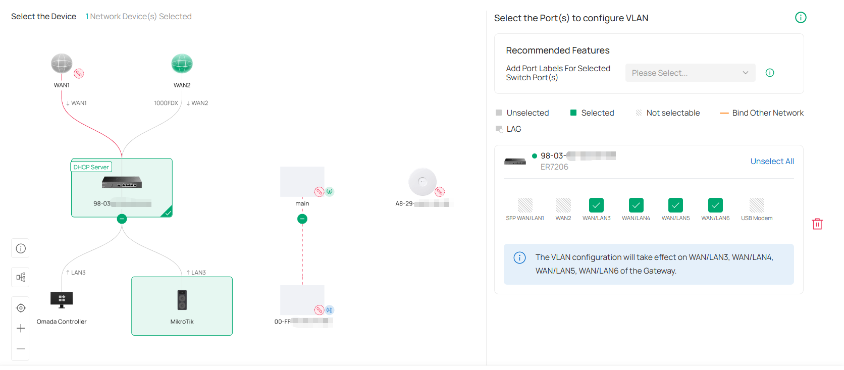
6. Configure recommended features if needed.
|
Port Isolation |
When enabled, Port Isolation will be applied to the selected ports to enhance security. |
|---|---|
|
Flow Control |
When enabled, 802.3 pause frames notify IPCs to temporarily buffer video data during network congestion, preventing frame loss that would occur when packets are dropped. This requires IPC support for the protocol. |
|
Add Port Labels For Selected Switch Port(s) |
This option is used to add labels to the selected switch ports, facilitating centralized port management on the Device Config > Switch Ports page. |
7. Click Next. Confirm your settings and click Apply. The VLAN network will be added to the list.
Now you can view the devices that are currently functioning in this VLAN through the topology view or check the configuration of this VLAN on the device ports through the port view.
Configure Multicast Features
You can configure multicast features on the Multicast page to optimize multicast traffic management.
1. Launch the controller and access a site.
2. Go to Network Config > Network Settings > LAN > Multicast. Click Add Multicast.
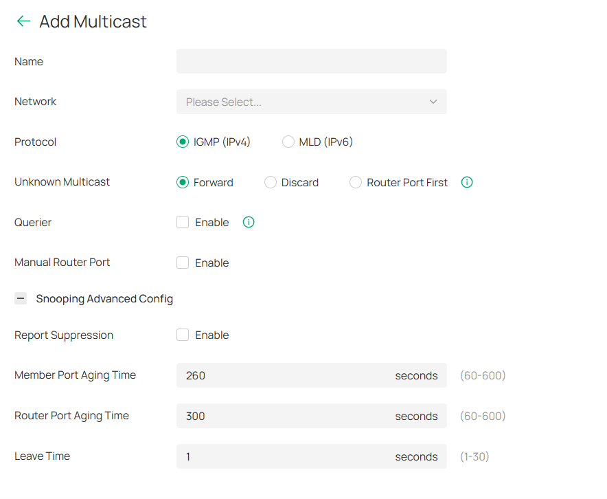
3. Configure the parameters and apply the settings.
|
Name |
Enter a name to identify the Multicast network. |
|---|---|
|
Network |
Select the target network for multicast configuration, which will automatically enable its multicast snooping. |
|
Protocol |
Choose between IGMP (IPv4) or MLD (IPv6) based on network protocol requirements. |
|
Unknown Multicast |
Specify handling method for unidentified multicast packets. Forward: Flood unknown multicast traffic within VLAN. Discard: Drop unknown multicast packets. Router Port First: Forward to router ports (static/dynamic) if available; otherwise flood within VLAN. |
|
Querier |
Set a switch as the querier for a specific network, and configure more parameters in Advanced Settings. |
|
Manual Router Port |
Manually set Static Router Port and Forbidden Router Port. Static Router Port: Select one or more ports to be the Static Router Ports in the network. All multicast data in this network will be forwarded through the static router ports. Forbidden Router Port: Select one or more ports to forbid them from being router ports in the network. |
|
Report Suppression |
When enabled, the switch will only forward the first IGMP report message for each multicast group to L3 devices during one query interval. This feature prevents duplicate report messages from being sent to the L3 devices. |
|
Member Port Aging Time |
Specify the aging time of the member ports in the Network. If the switch does not receive any IGMP membership report messages for a specific multicast group from a dynamic member port, it will no longer consider this port as a member port of this multicast group and delete it from the multicast forwarding table. |
|
Router Port Aging Time |
Specify the aging time of the router ports in the Network. If the switch does not receive any IGMP general query message from a dynamic router port within the router port aging time, the switch will no longer consider this port as a router port and delete it from the router port list. |
|
Leave Time |
Specify the leave time for the Network. When the switch receives a leave message from a port to leave a multicast group, it will wait for a leave time before removing the port from the multicast group. During the period, if the switch receives any report messages from the port, the port will not be removed from the multicast group. Exceptions are as follows: If the member port ages out before the Leave Time ends and no report messages are received, the port will be removed from the multicast group once its Member Port Aging Time ends. The Leave Time mechanism will not take effect when Fast Leave takes effect. |
Configure Network Isolation
When creating a VLAN, you can configure whether to isolate network segments in the advanced settings.
You can also configure network isolation on the Isolation Settings page to manage communication between VLANs.
Note: Network Isolation is only supported for networks with the Omada Gateway configured as the DHCP Server Device.
1. Launch the controller and access a site.
2. Go to Network Config > Network Settings > LAN > Isolation Settings.
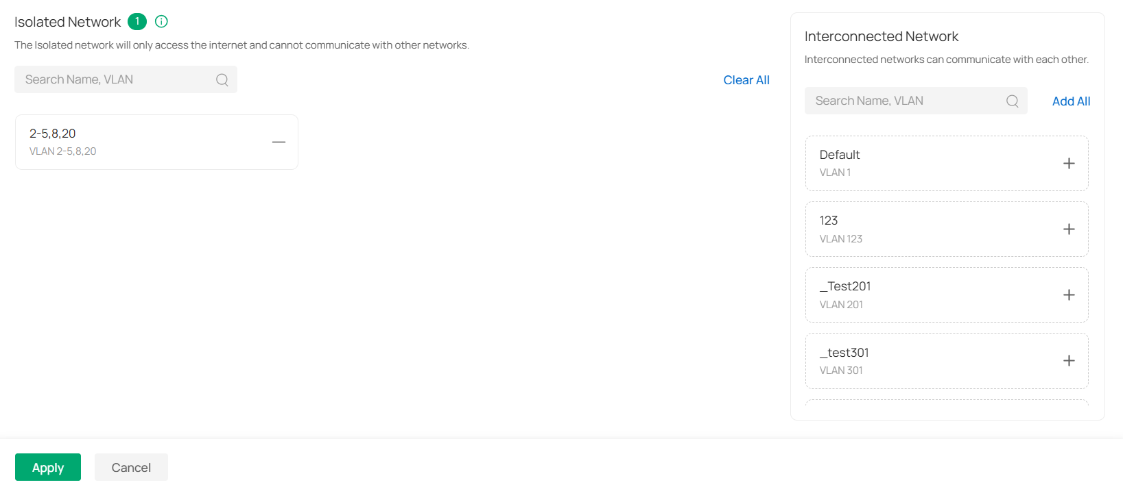
3. Select the network to be isolated. Click the Add button on the right or drag to move the Network to the Isolated Network area to isolate it.
Configure LAN DNS
1. Launch the controller and access a site.
2. Go to Network Config > Network Settings > LAN > LAN DNS.
3. Click Create New LAN DNS to load the following page, set the parameters, and save the settings.
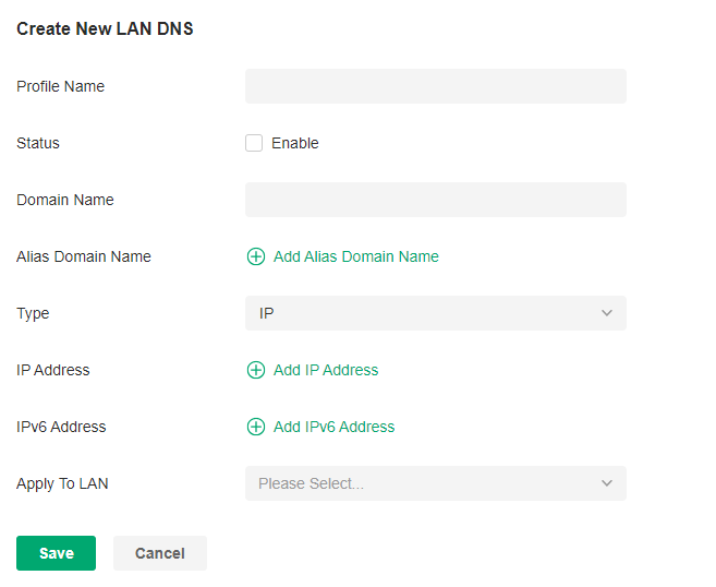
|
Profile Name |
Specify the name of the profile. |
|---|---|
|
Status |
Whether to enable this entry. |
|
Domain Name |
Enter the domain name. |
|
Alias Domain Name |
If a server provides different services and has multiple domain names, you can enter them here. |
|
Type |
There are three options, IP, CNAME, and FORWARD. IP: When selected, the gateway will respond to the DNS query of the specified domain name, and use the configured IP address as the DNS response to directly reply to the LAN host. Select this type when there is a web server in the intranet and you want hosts in the LAN to access the web server through private IP addresses instead of public IP addresses. CNAME: When selected, the gateway will map the domain name to the configured CNAME domain name, send it to the DNS server for query, and then reply to the LAN host with the IP corresponding to the CNAME domain name. FORWARD: When selected, the gateway will forward the DNS query of the LAN host to the specified DNS server, and reply the DNS response to the LAN host. The forwarding priority is higher than other public configurations, such as the DNS Server configured on the WAN port. |
|
IP Address |
When the Type is IP, it is the IPv4 address of the returned DNS response. |
|
IPv6 Address |
When the Type is IP, it is the IPv6 address of the returned DNS response. |
|
Apply To LAN |
When the Type is IP or CNAME, it is the LAN network to which the rule applies. You can choose to apply all LANs or apply to a single LAN or multiple LANs. |
|
CNAME |
When Type is CNAME, set the domain name to which Domain Name and Alias Domain Name need to be mapped. |
|
DNS Server |
When the Type is FORWARD, set the Domain Name and Alias Domain Name to be forwarded to a specific DNS Server, up to two DNS Servers can be configured. |
Configuring Wireless Networks
Wireless networks enable your wireless clients to access the internet. Once you set up a wireless network, your APs typically broadcast the network name (SSID) in the air, through which your wireless clients connect to the wireless network and access the internet.
A WLAN group is a combination of wireless networks. Configure each group so that you can flexibly apply these groups of wireless networks to different APs according to your needs.
After setting up basic wireless networks, you can further configure WLAN Schedule, 802.11 Rate Control, MAC Filter, and other advanced settings.
Set Up Basic Wireless Networks
Configuration
To create, configure and apply wireless networks, follow these steps:
1) Create a WLAN group.
2) Create Wireless Networks
3) Apply the WLAN group to your APs
Step 1: Create a WLAN Group
Note:
The controller provides a default WLAN group. If you simply want to configure wireless networks for the default WLAN group and apply it to all your APs, skip this step.
1. Launch the controller and access a site.
2. Go to Network Config > Network Settings > WLAN to load the following page.
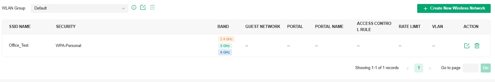
3.  Select Create New Group from the drop-down list of WLAN Group to load the following page. Enter a name to identify the WLAN group.
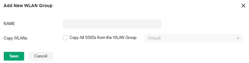
4. (Optional) If you want to create a new WLAN group based on an existing one, check Copy All SSIDs from the WLAN Group and select the desired WLAN group. Then you can further configure wireless networks based on current settings.
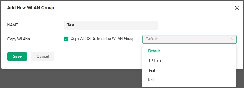
5. Click Save. The new WLAN Group is added to the WLAN Group list. You can select a WLAN Group from the list to further create and configure its wireless networks. You can click the Edit icon to edit the name of the WLAN Group. You can click the Delete icon to delete the WLAN Group.
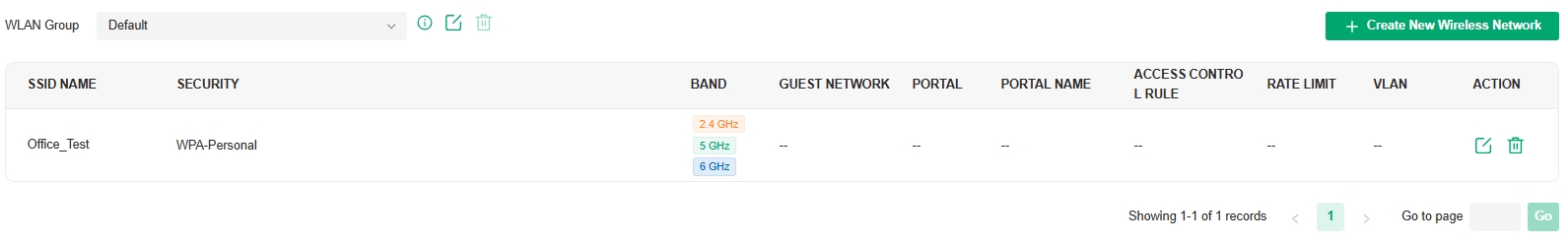
Step 2: Create Wireless Networks
1. Select the WLAN group for which you want to configure wireless networks from the drop-down list of WLAN Group.

2. Click Create New Wireless Network to load the following page. Configure the basic parameters for the network.
Note:
The 6 GHz band is only available for certain devices.
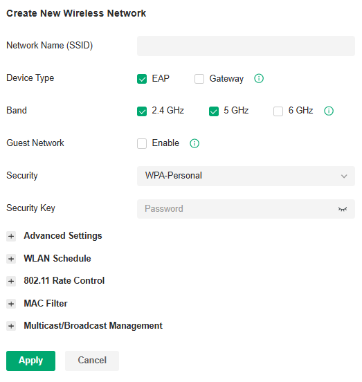
|
Network Name (SSID) |
Enter the network name (SSID) to identify the wireless network. The users of wireless clients choose to connect to the wireless network according to the SSID, which appears on the WLAN settings page of wireless clients. |
|---|---|
|
Device Type |
Select the type of devices that the wireless network can apply to. |
|
Band |
Enable the radio band(s) for the wireless network. When 6GHz is turned on, Security cannot be PPSK with/without RADIUS since 6GHz does not support them. |
|
Guest Network |
With Guest Network enabled, all the clients connecting to the SSID are blocked from reaching any private IP subnet. |
|
Security |
Select the encryption method for the wireless network based on needs |
3. Select the security strategy for the wireless network.
■ None
With None selected, the hosts can access the wireless network without authentication, which is applicable to lower security requirements.

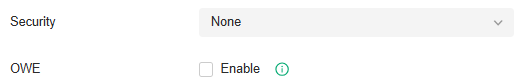
|
OWE |
Opportunistic Wireless Encryption, also known as Enhanced Open, is a certification provided by the Wi-Fi Alliance as part of the WPA3 wireless security standard. OWE will enable two wireless APs per radio, one for access of OWE-supported stations, and one for access of other stations. An SSID with OWE enabled will be counted as two SSID entries. |
|---|
■ WPA-Personal
With WPA-Personal selected, traffic is encrypted with a Security Key you set,

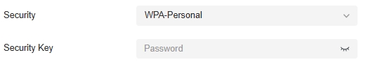
|
Security Key |
Specify a security key to encrypt the traffic. |
|---|
■ WPA-Enterprise
WPA-Enterprise requires an authentication server to authenticate wireless clients, and probably an accounting server to record the traffic statistics.

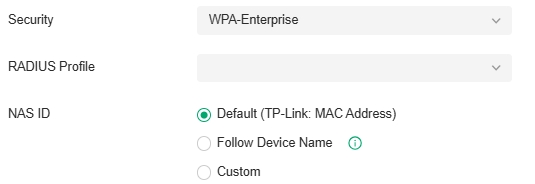
|
RADIUS Profile |
Select a RADIUS Profile, which records the settings of the authentication server and accounting server. You can create a RADIUS Profile by clicking Create New Radius Profile from the drop-down list of RADIUS Profile. For details, refer to the network profile configuration section in this guide. |
|---|---|
|
NAS ID |
Configure a Network Access Server Identifier (NAS ID) for the authentication. Authentication request packets from the controller to the RADIUS server carry the NAS ID. The RADIUS server can classify users into different groups based on the NAS ID, and then choose different policies for different groups. The NAS ID can be a default one (TP-Link: MAC Address), follow the device name, or a customized one. |
■ PPSK without RADIUS
PPSK (private pre-shared key) can provide a unique PSK for each wireless user. Compared with the traditional SSID solution with one password for all users, it is more secure.

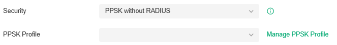
|
PPSK Profile |
Select a PPSK Profile, which records the PPSK settings. You can create a PPSK Profile by clicking Create New PPSK Profile from the drop-down list of PPSK Profile. For details, refer to the network profile configuration section in this guide. |
|---|
■ PPSK with RADIUS
PPSK (private pre-shared key) can provide a unique PSK for each wireless use. PPSK with RADIUS requires an authentication server to authenticate wireless clients and probably an accounting server to record the traffic statistics. The SSID will not be applied to the device firmware not supporting PPSK.

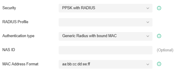
|
RADIUS Profile |
Select a RADIUS Profile, which records the settings of the authentication server and accounting server. You can create a RADIUS Profile by clicking Create New Radius Profile from the drop-down list of RADIUS Profile. For details, refer to the network profile configuration section in this guide. |
|---|---|
|
Authentication type |
Choose the authentication type. Generic Radius with bound MAC: This method uses a device’s unique MAC address as the username and password for a RADIUS server to grant or deny network access. This type needs to specify device MAC addresses. EKMS: The EKMS (Eleven Key Matching Service) authentication type is used to connect to the ElevenOS server. Only the EKMS authentication method in PPSK with RADIUS supports domain name. Generic Radius with unbound MAC: This method uses a client’s MAC address as the username and password for a RADIUS server to grant or deny network access. This type does not need to specify device MAC addresses. |
|
NAS ID |
Configure a Network Access Server Identifier (NAS ID) for the authentication. Authentication request packets from the controller to the RADIUS server carry the NAS ID. The RADIUS server can classify users into different groups based on the NAS ID, and then choose different policies for different groups. |
|
MAC Address Format |
Select clients’ MAC address format which the controller uses for authentication. Then configure the MAC addresses in the specified format as usernames for the clients on the RADIUS server. |
4. (Optional) You can also configure Advanced Settings, WLAN Schedule, 802.11 Rate Control, and MAC Filter, and more according to your needs. Related topics are covered later in this chapter.
5. Click Apply. The new wireless network is added to the wireless network list under the WLAN group. You can click the Edit icon in the ACTION column to edit the wireless network. You can click the Delete icon in the ACTION column to delete the wireless network.
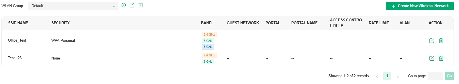
Step 3: Apply the WLAN Group
Note:
The controller provides a default WLAN group. If you simply want to configure wireless networks for the default WLAN group and apply it to all your APs, skip this step.
■ Apply to a Single AP
Go to Devices > Device List. In the device list, click an AP, click Manage Device and go to Config > Wireless > WLANs. Select the WLAN group and apply the settings.
■ Apply to APs in batch
1. Go to Devices > Device List. Click Batch Action, select Batch Config, check the boxes of your desired APs, and click Config.
2. In the Properties window, go to Wireless > WLANs. Select the WLAN group and apply the settings.
Configure Advanced Settings
Launch the controller and access a site. Go to Network Config > Network Settings > WLAN, click the Edit icon in the ACTION column of the wireless network which you want to configure, and click Advanced Settings to load the following page. Configure the parameters and click Apply.
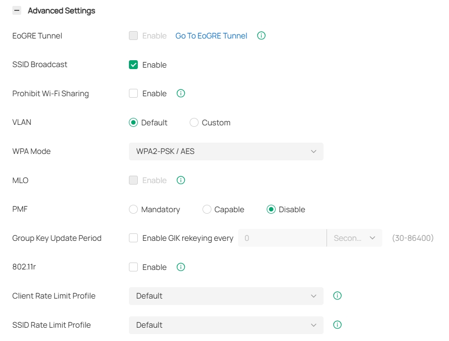
|
EoGRE Tunnel |
Toggle on to enable the EoGRE (Ethernet over GRE) Tunnel for the wireless network. Note: If the function is unavailable, go to Device Config > EAP > EoGRE Tunnel to enable the feature globally. |
|---|---|
|
SSID Broadcast |
With SSID Broadcast enabled, APs broadcast the SSID (network name) in the air so that wireless clients can connect to the wireless network, which is identified by the SSID. With SSID Broadcast disabled, users of wireless clients must enter the SSID manually to connect to the wireless network. |
|
Prohibit Wi-Fi Sharing |
When enabled, the connected clients will be prohibited to share the Wi-Fi with other clients. |
|
VLAN |
Configure the uplink port VLAN(s) corresponding to the SSID. Default: Using untagged transmission. Custom: Configure an SSID-based VLAN pool by binding one or multiple networks (by network) or manually entering one or multiple VLAN IDs (by VLAN). When a client connects to the SSID, it will be assigned to a VLAN in the VLAN pool you configured. If a device does not support multiple VLANs, the smallest VLAN you configured will be applied to the SSID. |
|
WPA Mode |
If you select WPA-Personal or WPA-Enterprise as the security strategy, you can select the WPA Mode including the version of WPA, and the encryption type. Select the version of WPA according to your needs. Select the encryption type. Some encryption type is only available under certain circumstances. AES: AES stands for Advanced Encryption Standard. Auto: APs automatically decide the encryption type in the authentication process. |
|
MLO |
MLO (Multi-Link Operation) enables Wi-Fi 7 devices to simultaneously send and receive data across different frequency bands and channels. This ensures fast and reliable connections even in dense network environments. |
|
PMF |
Protected Management Frames (PMF) provide protection for unicast and multicast management action frames. When Mandatory is selected, non-PMF-capable clients may fail to connect to the network. Disable: Disables PMF for a network. It is not recommended to use this setting, only in case non-PMF-capable clients experience connection issues with the “Capable” option. Capable: Both types of clients, capable of PMF or not, can connect to the network. Clients capable of PMF will negotiate it with the AP. Mandatory: Only PMF-capable clients can connect to the network. |
|
Group Key Update Period |
If you select WPA-Personal or WPA-Enterprise as the security strategy, you can specify whether and how often the security key changes. If you want the security key to change periodically, enable GIK (Group Integrity Key) rekeying and specify the time period. |
|
802.11r |
802.11r allows faster roaming when both the AP and client have 802.11r capabilities. However, older devices may be incompatible with the feature. Currently 802.11r does not support WPA3-Enterprise encryption. |
|
Client Rate Limit Profile |
Specify the profile to limit the download and upload rates of each client to balance bandwidth usage. You can use the default profile or custom a profile. |
|
SSID Rate Limit Profile |
Specify the profile to limit the download and upload rates of each wireless band. Bandwidth is shared among all clients connected to the same wireless band of the same AP. You can use the default profile or custom a profile. Note: This feature requires new firmware updates for Omada APs, and the rate limit settings will only take effect on those APs running firmware that supports the feature. |
Configure Hotspot 2.0
Overview
Hotspot 2.0 is a wireless network technology based on the IEEE 802.11u standard. It provides a simplified network selection mechanism for wireless clients, enabling them to automatically discover and securely access Hotspot 2.0-certified Wi-Fi networks.
Hotspot 2.0 is only available for a wireless network using WPA3-Enterprise encryption.
Configuration
Launch the controller and access a site. Go to Network Config > Network Settings > WLAN, click the Edit icon in the ACTION column of a wireless network that is using WPA3-Enterprise encryption, and click Hotspot 2.0 to load the following page. Enable Hotspot 2.0 and configure the parameters. Then click Apply.
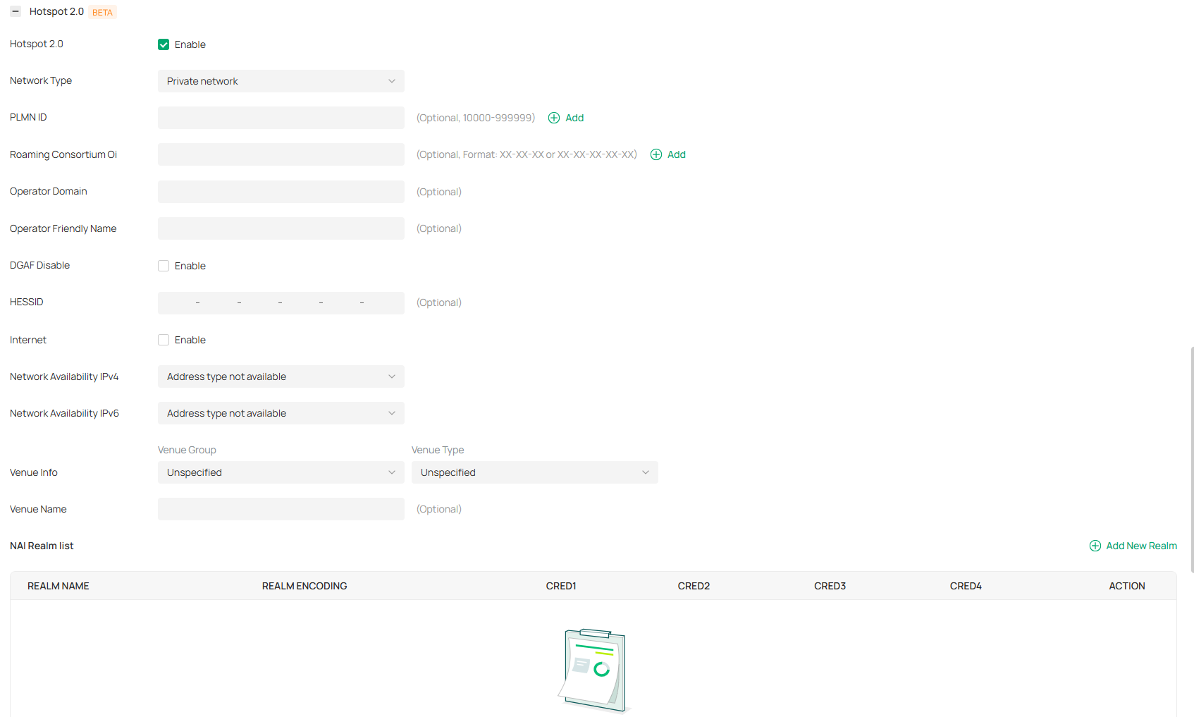
|
Network Type |
Specify the 802.11u network type: public, private, or guest network. |
|---|---|
|
PLMN ID |
Enter the PLMN (Public Land Mobile Network) ID of the 802.11u 3GPP cellular network, which consists of the MCC (Mobile Country Code) and MNC (Mobile Network Code). Wireless clients can obtain this information through ANQP queries to determine whether to access the network. This is applicable to networks that have roaming relationships with mobile operators. |
|
Roaming Consortium Oi |
Enter the 802.11u roaming organization identifiers. For a network that has roaming relationships with other network operators, you can configure a roaming organization list for wireless clients to automatically identify trusted roaming network partners. |
|
Operator Domain |
Enter the domain name of the access network operator. Wireless clients can obtain this information through ANQP queries as the basis for network selection. |
|
Operator Friendly Name |
Network operator friendly name. This parameter can be used to define the names of different language environments, so that users of different languages can easily select the network. Currently, only English format input is provided. |
|
DGAF Disable |
In DGAF (downstream group-addressed forwarding) disable mode, the AP will not forward downstream multicast and broadcast packets. Downstream multicast and broadcast packets use the same GTK (Group Temporal Key) key, which poses a security risk. The AP will discard these ARP and multicast packets to prevent attackers from exploiting the vulnerability that all clients in the same BSS use the same GTK key to forge group address frames and attack clients. This function is disabled by default. When it is enabled, some multicast services will be unavailable. To ensure normal internet access, the AP will enable the ARP proxy and disable ARP-to-unicast conversion. |
|
HESSID |
Homogenous Extended Service Set Identifier. It is used to identify the same type of ESS network set. An area may have multiple Hotspot 2.0 networks. Based on the unique HESSID, wireless clients can identify which networks provide the same service without having to re-acquire network parameters. HESSID should be consistent with one of the BSSIDs of the APs in the zone. |
|
Internet |
Internet access support status (network reachability). |
|
Network Availability IPv4 |
Available type information of IPv4 addresses. When a wireless client accesses a Hotspot 2.0 network, the AP can pass the available types of IPv4 addresses in the network to the client as ANQP parameters, so that the client can understand the types of IP addresses that can be obtained after accessing the network. |
|
Network Availability IPv6 |
Available type information of IPv6 addresses. When a wireless client accesses a Hotspot 2.0 network, the AP can pass the available types of IPv6 addresses in the network to the client as ANQP parameters, so that the client can understand the types of IP addresses that can be obtained after accessing the network. |
|
Venue Info |
Indicates the venue information using the combination of the network's venue group and venue type (using the international building code). When a wireless client attempts to access a Hotspot 2.0 network, it can obtain the location type information of the current network from the AP for network selection. |
|
Venue Name |
Network’s venue name, identifying the physical location of the network. |
|
NAI Realm list |
Add a profile to identify and describe a NAI (Network Access Identifier) realm accessible using the AP, and the method that this NAI realm uses for authentication. Realm name: The name of the NAI realm. Usually the domain name of the service provider. Realm Encoding: NAI realm name format. Two formats are supported: •RFC4282: Realm formatted according to RFC 4282. •UTF-8: UTF-8 formatted string not formatted according to IETF RFC 4282. EAP Method: EAP authentication method supported by the NAI realm. Authentication param: Configure the EAP authentication parameter identifier and authentication parameters. |
Configure WLAN Schedules
Overview
WLAN Schedule can turn on or off your wireless network in the specific time period as you desire.
Configuration
Launch the controller and access a site. Go to Network Config > Network Settings > WLAN, click the Edit icon in the ACTION column of the wireless network which you want to configure, and click WLAN Schedule to load the following page. Enable WLAN schedule and configure the parameters. Then click Apply.
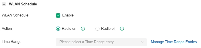
|
Action |
Radio On: Turn on your wireless network within the time range you set, and turn it off beyond the time range. Radio Off: Turn off your wireless network within the time range you set, and turn it on beyond the time range. |
|---|---|
|
Time Range |
Select the Time Range for the action to take effect. You can create a Time Range entry by clicking Create New Time Range Entry from the drop-down list of Time Range. For details, refer to the network profile configuration section in this guide. |
Configure 802.11 Rate Control
Overview
Note:
802.11 Rate Control is only available for certain devices.
802.11 Rate Control can improve performance for higher-density networks by disabling lower bit rates and only allowing the higher. However, 802.11 Rate Control might make some legacy devices incompatible with your networks, and limit the range of your wireless networks.
Configuration
Launch the controller and access a site. Go to Network Config > Network Settings > WLAN, click the Edit icon in the ACTION column of the wireless network which you want to configure, and click 802.11 Rate Control to load the following page. Select one or multiple bands to enable minimum data rate control according to your needs, move the slider to determine what bit rates your wireless network allows, and configure the parameters. Then click Apply.
Note:
The 6 GHz band is only available for certain devices.
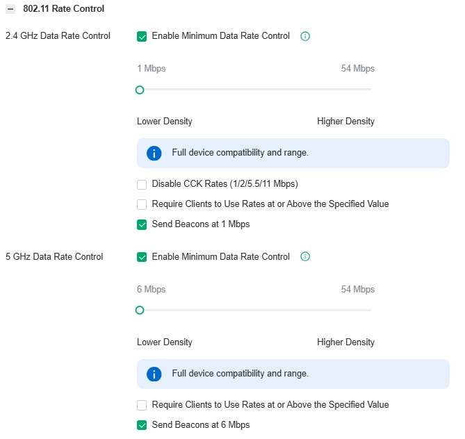
|
Disable CCK Rates (1/2/5.5/11 Mbps) |
Select whether to disable CCK (Complementary Code Keying), the modulation scheme which works with 802.11b devices. Disable CCK Rates (1/2/5.5/11 Mbps) is only available for 2.4 GHz band. |
|---|---|
|
Require Clients to Use Rates at or Above the Specified Value |
Select whether or not to require clients to use rates at or above the value specified on the minimum data rate controller slider. |
|
Send Beacons at 1 Mbps/6 Mbps |
Select whether or not to send Beacons at the minimum rate of 1Mbps for 2.4 GHz band or 6Mbps for 5 GHz band. |
Configure MAC Filtering
Overview
MAC Filter allows or blocks connections from wireless clients of specific MAC addresses.
Configuration
Launch the controller and access a site. Go to Network Config > Network Settings > WLAN, click the Edit icon in the ACTION column of the wireless network which you want to configure, and click MAC Filter to load the following page. Enable MAC Filter and configure the parameters. Then click Apply.

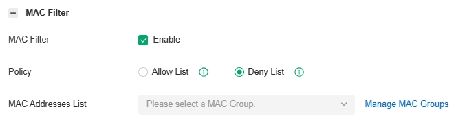
|
Policy |
Allow List: Allow the connection of the clients whose MAC addresses are in the specified MAC Address List, while blocking others. Deny List: Block the connection of the clients whose MAC address are in the specified MAC Addresses List, while allowing others. |
|---|---|
|
MAC Address List |
Select the MAC Group which you want to allow or block according to the policy. You can create new MAC group by clicking + Create New MAC Group from the drop-down list of MAC Address List. For details, refer to the network profile configuration section in this guide. |
Configure Multicast/Broadcast Management
Overview
Multicast/Broadcast Management allows packet conversion and multicast filtering.
Configuration
Launch the controller and access a site. Go to Network Config > Network Settings > WLAN, click the Edit icon in the ACTION column of the wireless network which you want to configure, and click Multicast/Broadcast Management to load the following page. Configure the parameters. Then click Apply.

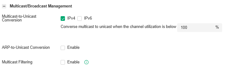
|
Multicast-to-Unicast Conversion |
When the channel utilization is below the set value, the Wireless Device will convert the IPv4/IPv6 multicast packets into unicast packets and send them to the corresponding clients based on the learned multicast relationships. This improves the transmission efficiency of IPv4/IPv6 multicast. |
|---|---|
|
ARP-to-Unicast Conversion |
When enabled, the controller will convert ARP packets into unicast packets. |
|
Multicast Filtering |
When enabled, the device will filter the multicast packets of the specified protocols. Improper settings may cause network issues |
|
Filtering Protocols |
Choose IGMP/mDNS/ND/Others according to your need. Choose Others for MAC-based filtering, which will filter IP multicast packets that are not using IGMP, MLD, mDNS, or ND protocols. |
|
MAC Group |
If you want to allow packets from specific addresses to pass through, you can choose MAC Group and Create New MAC Group. Here you can set MAC Group Name and choose different methods to add the MAC Address. |
Configure WLAN Optimization
Overview
WLAN Optimization helps improve the wireless network performance. With the WLAN Optimization feature, the controller will detect WiFi interference and monitor the wireless environment. Based on the environmental factors including network topology, deployment size, traffic, and client factors, the controller can determine the optimum wireless configurations (such as channel, bandwidth, power, etc.) for the access points (APs), and thus ensures that wireless clients of each AP can enjoy better WiFi experience.
In WLAN Optimization, the results of the last 10 scans are displayed.
In Optimization History, the past optimization records are displayed, and you can also restore the previous optimization results if needed.
Initiate WLAN Optimization
Note:
The connection to internet will be lost for several minutes during the scanning and optimization. Please select a spare time of network to start scanning.
1. Launch the controller and access a site. Go to Network Config > Network Settings > WLAN > WLAN Optimization.
2. Click Optimization Adjustment (recommended) or Global Optimization to initiate the optimization.
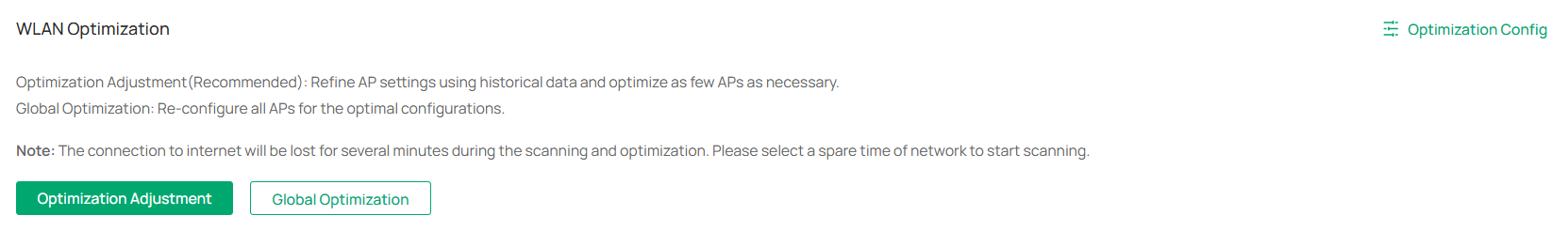
|
Optimization Adjustment |
The system will perform wireless optimization on some APs based on historical optimization results, historical client behavior, and the current wireless environment. To ensure the connection stability of wireless clients, the system will adjust as few wireless configurations as possible. This optimization option is recommended, but it is only available for non-initial optimizations since it requires historical optimization data. |
|---|---|
|
Global Optimization |
The system will perform wireless optimization on all APs, selecting the appropriate wireless configurations. |
3. The controller will scan the wireless environment to conclude the optimum WLAN network configurations and display the result after completing the optimization.

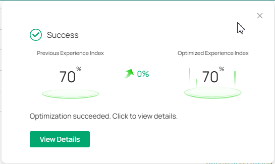
4. Click View Details to display more info. You can click Apply Previous Settings if you want to restore the previous optimization results.
Tip:
You can also view the optimization results in the Optimization History.
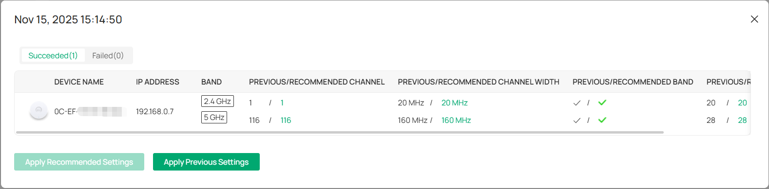
Customize Optimization Config
If you want to custom optimization configurations, click Optimization Config on the WLAN Optimization page, then set the parameters according to actual needs.

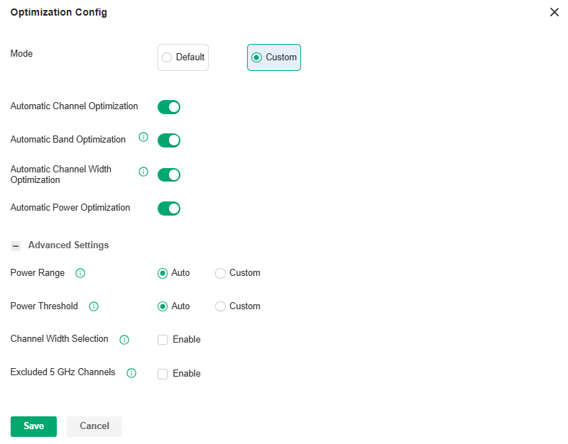
|
Mode |
Specify the optimization mode. Default: The controller will conduct the optimization with the default configurations. Custom: The controller will conduct the optimization with the configurations you set. |
|---|---|
|
Automatic Channel Optimization |
Enable this function, and the controller will scan the wireless environment to conclude the optimum operation channels for the APs. |
|
Automatic Band Optimization |
Enable this function in a high-density deployment scenario, and the controller will scan the wireless environment and determine whether to turn off some radio bands to reduce network interference, hence improving the performance of the entire network. |
|
Automatic Channel Width Optimization |
Enable this function in a high-density deployment scenario, and the controller will scan the wireless environment and determine whether to reduce some radio bandwidth to reduce network interference, hence improving the performance of the entire network. |
|
Automatic Power Optimization |
Enable this function, and the controller will scan the wireless environment to conclude the optimum transmission power for the APs. |
|
Power Range |
Select Custom if you want to optimize the power within the specified range. You can limit the transmit power range of each AP/wireless routers after the power deployment is completed. For high-density deployment, you can try to set a smaller power range. An over-low value may lead to limited coverage, while an over-high value may lead to strong interference. (Note: The deployment may fail if the minimum power you select exceeds the maximum power of the AP to be deployed.) |
|
Power Threshold |
Select Custom if you want to optimize the power within the specified threshold. You can adjust the power deployment override threshold according to the actual deployment height and spacing of APs/wireless routers, achieving optimal wireless coverage after RF optimization. The larger the threshold, the larger the adjusted overall power value. |
|
Channel Width Selection |
Select the channel width for each band, and the optimization will maintain the selected channel width. |
|
Excluded 5 GHz Channels |
When enabled, you can specify the channels so they will not execute the automatic optimization. |
Exclude APs from WLAN Optimization
If you want to exclude cetain APs from WLAN optimization, locate the Excluded APs List on the WLAN Optimization page, click Add to add the APs.
Some APs will be added to the list automatically, including APs in the mesh network and APs with unsupported firmware.
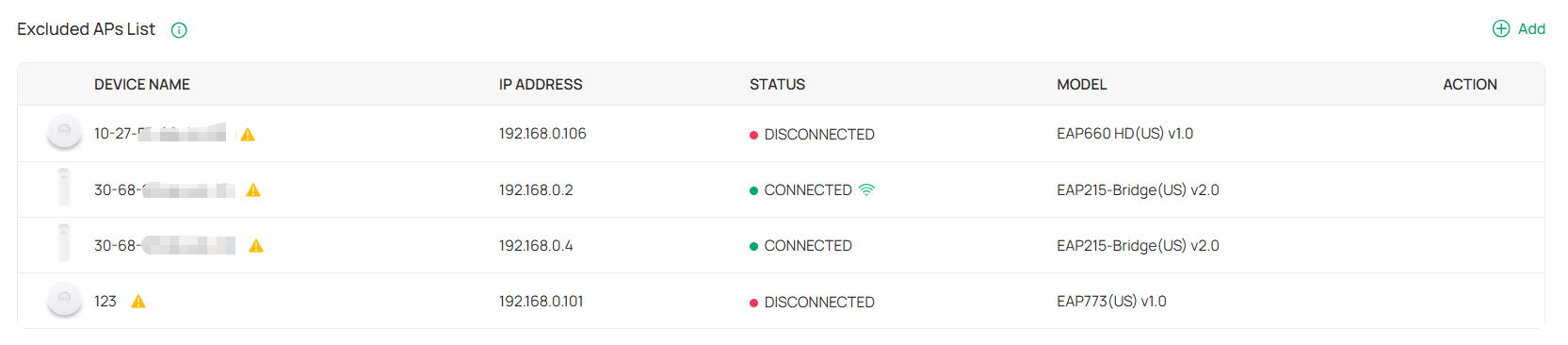

Configuring Network Authentication
Authentication is a portfolio of features designed to authorize network access to clients, which enhances the network security. Omada provides authentication services covering all the needs to authenticate both wired and wireless clients.
Configure MAC-Based Authentication
Overview
Portal authentication provides authentication service to the clients that only need temporary access to the network, such as the customers in a restaurant or in a supermarket. To access the network, these clients need to enter the authentication login page and use the correct login information to pass the authentication. In addition, you can customize the authentication login page and specify a URL which the authenticated clients will be redirected to.
Portal authentication takes effect on SSIDs and LAN networks. EAPs authenticate wireless clients which connect to the SSID with Portal configured, and the gateway authenticates wired clients which connect to the network with Portal configured. To make Portal authentication available for wired and wireless clients, ensure that both the gateway and EAPs are connected and working properly.
The controller provides several types of Portal authentication:
■ No Authentication
With this authentication type configured, clients can pass the authentication and access the network without providing any login information. Clients just need to accept the terms (if configured) and click the Login button.
■ Simple Password
With this authentication type configured, clients are required to enter the correct password to pass the authentication. All clients use the same password which is configured in the controller.
■ Hotspot
With this authentication type configured, clients can access the network after passing any type of the authentication:
• Voucher
Clients can use the unique voucher codes generated by the controller within a predefined time usage. Voucher codes can be printed out from the controller, so you can print the codes and distribute them to your costumers to tie the network access to consumption.
• Local User
Clients are required to enter the correct username and password of the login account to pass the authentication.
• SMS
Clients can get verification codes using their mobile phones and enter the received codes to pass the authentication.
• RADIUS
Clients are required to enter the correct username and password which are stored in the RADIUS server to pass the authentication.
• Form Auth
Clients are required to fill in a survey created by the network administrator to pass the authentication. It can be used for collecting feedback from your clients.
■ RADIUS Server
Clients are required to enter the correct username and password created on the RADIUS server to pass the authentication.
■ External Portal Server
The option of External Portal Server is designed for the developers. They can customize their own authentication type like Google account authentication according to the interface provided by the Controller.
Clients will be redirected to the Google login page and are required to complete the Google account login to pass the authentication.
Portal authentication can work with Access Control Policy, which grant specific network access to the users with valid identities. You can determine that the clients which didn’t pass Portal authentication can only access the network resources allowed by Access Control Policy.
■ Pre-Authentication Access
Pre-Authentication Access allows unauthenticated clients to access the specific network resources.
■ Authentication-Free Client
Authentication-Free Clients allows the specific clients to access the specific network resources without authentication.
Create New Portal
1. Launch the controller and access a site.
2. Go to Network Config > Authentication > Portal.
3. On Portal tab, click Create New Portal. Specify the portal name and enable Portal.

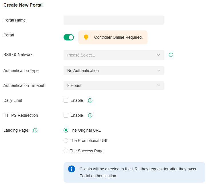
4. Select the SSIDs and LAN networks for the portal to take effect. The clients connected to the selected SSIDs or LAN networks will have to log into a web page to establish verification before accessing the network.
5. Select the Authentication Type and configure authentication settings.
|
Authentication Timeout |
Select the login duration. Clients will be off-line after the authentication timeout. |
|---|---|
|
Daily Limit |
Click the checkbox to enable Daily Limit. With this feature enabled, after authentication times out, clients cannot get authenticated again until the next day. With this feature disabled, after authentication times out, clients can get authenticated again without limit. |
■ Simple Password
|
Password |
Specify the password for the portal. |
|---|---|
|
Authentication Timeout |
Select the login duration. Clients will be off-line after the authentication timeout. |
|
Type |
Select one or more authentication types according to your needs. Clients can access the network after passing any type of the authentication. |
|---|
With different types of Hotspot selected, configure the related parameters.
• Voucher Portal
|
Voucher |
Select Voucher and click Voucher Manager to manage the voucher codes. Refer to the voucher configuration chapter in this guide for detailed information about how to create vouchers. |
|---|
• Local User Portal
|
Local User |
Select Local User and click User Management to manage the information of the login accounts. Refer to the account configuration chapter in this guide for detailed information about how to create Local Users. |
|---|
• SMS Portal
Select SMS and configure the required parameters in the SMS section.
|
SMS |
Clients can get verification codes using their mobile phones and enter the received codes to pass the authentication. |
|---|---|
|
Twilio SID |
Enter the Account SID for Twilio API Credentials. |
|
Auth Token |
Enter the Authentication Token for Twilio API Credentials. |
|
Operating Phone Number |
Enter the phone number that is used to send verification messages to the clients. |
|
Maximum User Numbers |
Click the checkbox and enter the maximum number of users allowed to be authenticated using the same phone number at the same time. |
|
Authentication Timeout |
Select the login duration. The client needs to log in again on the web authentication page to access the network. |
|
Preset Country Code |
Enter the default country code that will be filled automatically on the authentication page. |
• RADIUS Portal
Select RADIUS and configure the required parameters in the RADIUS section.
|
Authentication Timeout |
Clients are required to enter the correct username and password which are stored in the RADIUS server to pass the authentication. |
|---|---|
|
RADIUS Profile |
Select the RADIUS profile you have created. If no RADIUS profiles have been created, click Create New RADIUS Profile from the drop-down list or Manage RADIUS Profile to create one. The RADIUS profile records the information of the RADIUS server which provides a method for storing the authentication information centrally. |
|
Portal Logout |
Check the box to allow clients to log out of the portal by accessing a URL (portal.tplink.net/portal/logout by default). You can change the default URL by editing portal.logout.domain in the omada.properties file. Some devices may require firmware update to support Portal Logout. Please refer to Configuration Result for details. |
|
NAS ID |
Configure a Network Access Server Identifier (NAS ID) on the portal. Authentication request packets from the controller to the RADIUS server carry the NAS ID. The RADIUS server can classify users into different groups based on the NAS ID, and then choose different policies for different groups. |
|
Disconnected Requests |
With the feature enabled, the controller will listen on the receiver port for disconnect requests from the RADIUS server. When the controller receives the disconnect requests in correct format, the controller will terminate the RADIUS authentication session of the clients. Note that the feature is available only when the controller is accessible to the RADIUS server. |
|
Receiver Port |
Specify the port on which the controller listens when there are disconnect requests from the RADIUS server. Make sure that the specified port is not in use. |
|
Status |
The entry displays the status of the receiver port, including Running, Disabled, and Error. Running means that the port is available, Disabled means that the port is closed, and Error means that the port is already in use. |
• Configuring Form Authentication
Select Form Auth and click Create New Survey in the Form Authentication section. Then follow the on-screen instructions to create a survey by adding the type and number of questions you need. You can click Preview to view how the survey looks like on website and phone.
Click Publish and then the created survey can be used for form authentication. A survey cannot be edited after it is published.
|
Survey Name |
Specify a name for the survey for identification. |
|---|---|
|
Duration |
Specify how long clients can use the network after they pass the form authentication. |
Created surveys will be displayed for you to choose for the form authentication.
|
Authentication Timeout |
Select the login duration. Clients will be off-line after the authentication timeout. |
|---|---|
|
RADIUS Profile |
Select the RADIUS profile you have created. If no RADIUS profiles have been created, click Create New RADIUS Profile from the drop-down list or click Manage RADIUS Profile to create one. The RADIUS profile records information of the RADIUS server including the IP address, port and so on. |
|
NAS ID |
Configure a Network Access Server Identifier (NAS ID) on the portal. Authentication request packets from the controller to the RADIUS server carry the NAS ID. The RADIUS server can classify users into different groups based on the NAS ID, and then choose different policies for different groups. |
|
Disconnected Requests |
With the feature enabled, the controller will listen on the receiver port for disconnect requests from the RADIUS server. When the controller receives the disconnect requests in correct format, the controller will terminate the RAIDIUS authentication session of the clients. Note that the feature is available only when the controller is accessible to the RADIUS server. |
|
Receiver Port |
Specify the port on which the controller listens when there are disconnect requests from the RADIUS server. Make sure that the specified port is not in use. |
|
Status |
The entry displays the status of the receiver port, including Running, Disabled, and Error. Running means that the port is available, Disabled means that the port is closed, and Error means that the port is already in use. |
|
Authentication Mode |
Select the authentication protocol for the RADIUS server. |
|
Portal Customization |
Select Local Web Portal or External Web Portal. The authentication login page of Local Web Portal is provided by the built-in portal server of the controller. The External Web Portal is provided by external portal server. Enter the authentication login page’s URL provided by the external portal server in the External Web Portal URL field. |
|
Authentication Timeout |
Select the login duration. Clients will be off-line after the authentication timeout. |
|---|---|
|
LDAP Profile |
Select the LDAP profile you have created. If no LDAP profiles have been created, click Create New LDAP Profile from the drop-down list or click Manage LDAP Profile to create one. The LDAP profile records information of the LDAP server including the server address, port and so on. |
|
Portal Customization |
Select Local Web Portal or External Web Portal. The authentication login page of Local Web Portal is provided by the built-in portal server of the controller. The External Web Portal is provided by external portal server. Enter the authentication login page’s URL provided by the external portal server in the External Web Portal URL field. |
|
Custom Portal Server |
Specify the IP address or URL that redirect to an external portal server. |
|---|
|
Authentication Timeout |
Select the login duration. Clients will be off-line after the authentication timeout. |
|---|---|
|
Client ID |
Enter the Client ID provided by Google to integrate with Google OAuth 2.0. |
|
Client Secret |
Enter the Client Secret provided by Google to integrate with Google OAuth 2.0. |
6. Configure redirection and landing settings.
|
HTTPS Redirection |
Click the checkbox to enable HTTPS Redirection. With this feature enabled, the unauthorized clients will be redirected to the Portal page when they are trying to browse HTTPS websites. With this feature disabled, the unauthorized clients cannot browse HTTPS websites and are not redirected to the Portal page. |
|---|---|
|
Landing Page |
Select which page the client will be redirected to after a successful authentication. The Original URL: Clients are directed to the URL they request for after they pass Portal authentication. The Promotional URL: Clients are directed to the specified URL after they pass Portal authentication. |
(Optional) Portal Customization
When creating or editing a portal entry, you can customize the Portal page in the Portal Customization section.
Note:
Portal Customization is not available when you configure external authentication types.

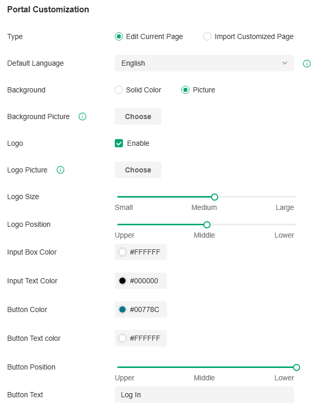
|
Type |
Select the type of the Portal page. Edit Current Page: Edit the related parameters to customize the Portal page based on the provided page. Import Customized Page: Click Import to import your unique Portal page for branding it as per your business. |
|---|---|
|
Default Language |
Select the default language displayed on the Portal page. The controller automatically adjusts the language displayed on the Portal page according to the system language of the clients. If the language is not supported, the controller will use the default language specified here. |
|
Background |
Select the background type. Solid Color: Configure your desired background color by entering the hexadecimal HTML color code manually or through the color picker. Picture: Click Choose and select a picture from your PC as the background. |
|
Logo |
Click to show the logo on the portal page. |
|
Logo Picture |
Click Choose and select a picture from your PC as the logo. |
|
Logo Size/ Logo Position |
Adjust the logo size and position on the Portal Page. |
|
Input Box Color/ Input Text Color |
(For cetain anthentication types) Configure your desired background and text color for the input box by entering the hexadecimal HTML color code manually or through the color picker. |
|
Button Color/ Button Text Color |
Configure your desired background and text color for the button by entering the hexadecimal HTML color code manually or through the color picker. |
|
Button Position |
Select the button position on the Portal Page. |
|
Button Text |
Enter the text for the button. |
|
Welcome Information |
Click the checkbox and enter text as the welcome information. You can specify the desired text font size and configure the text color by entering the hexadecimal HTML color code manually or through the color picker. |
|
Terms of Service |
Click the checkbox and enter text as the terms of service in the following box. Click Add Terms to enter the name and context of the terms which will appear after a client clicks the link in Terms of Service. |
|
Copyright |
Click the checkbox and enter text as the copyright in the following box. You can specify the desired text font size and configure the text color by entering the hexadecimal HTML color code manually or through the color picker. |
|
Show Redirection Countdown After Authorized |
When enabled, the system will show the portal’s redirection countdown. |
Click Advertisement Options and customize advertisement pictures on the authentication page if needed.

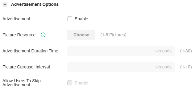
|
Advertisement |
Click the checkbox to enable the Advertisement feature. With this feature enabled, you can add advertisement pictures on the authentication page. These advertisement pictures will be displayed before the login page appears. |
|---|---|
|
Picture Resource |
Click Choose and select pictures from your PC as the advertisement pictures. When several pictures are added, they will be played in a loop. |
|
Advertisement Duration Time |
Enter the duration time for the advertisement pictures. For this duration, the pictures will be played in a loop. If the duration time is not enough for all the pictures, the rest will not be displayed. |
|
Picture Carousel Interval |
Enter the picture carousel interval. For example, if this value is set as 5 seconds, the first picture will be displayed for 5 seconds, followed by the second picture for 5 seconds, and so on. |
|
Allow Users To Skip Advertisement |
Click the checkbox to allow users to skip the advertisement. |
(Optional) Access Control
On Access Control tab, you can configure access control rules if needed.

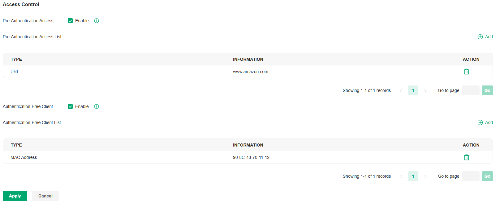
|
Pre-Authentication Access |
Click the checkbox to enable Pre-Authentication Access. With this feature enabled, unauthenticated clients are allowed to access the subnets and web resources specified in the Pre-Authentication Access List below. |
|---|---|
|
Pre-Authentication Access List |
Click Add to configure the IP range or URL which unauthenticated clients are allowed to access. |
|
Authentication-Free Policy |
Click the checkbox to enable Authentication-Free Policy. With this feature enabled, you can allow certain clients to access the internet without Portal authentication. |
|
Authentication-Free Client List |
Click Add and enter the IP address or MAC address of Authentication-Free clients. |
Configure Portal Authentication
Overview
802.1X provides port-based authentication service to restrict unauthorized clients from accessing to the network through publicly accessible switch ports. An 802.1X-enabled port allows only authentication messages and forbids normal traffic until the client passes the authentication.
Based on authenticated identity, 802.1X can also deliver customized services. For example, 802.1X and VLAN Assignment together make it possible to assign different authenticated users to different VLANs automatically.
802.1X authentication uses client-server model which contains three device roles: client/supplicant, authenticator and authentication server. This is described in the figure below:

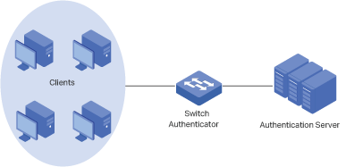
■ Client
A client, usually a computer, is connected to the authenticator via a physical port. We recommend that you install TP-Link 802.1X authentication client software on the client hosts, enabling them to request 802.1X authentication to access the LAN.
■ Authenticator
An authenticator is usually a network device that supports 802.1X protocol. As the above figure shows, the switch is an authenticator.
The authenticator acts as an intermediate proxy between the client and the authentication server. The authenticator requests user information from the client and sends it to the authentication server; also, the authenticator obtains responses from the authentication server and sends them to the client. The authenticator allows authenticated clients to access the LAN through the connected ports but denies the unauthenticated clients.
■ Authentication Server
The authentication server is usually the host running the RADIUS server program. It stores information of clients, confirms whether a client is legal and informs the authenticator whether a client is authenticated.
Based on authenticated identity, 802.1X can also deliver customized services. For example, 802.1X and VLAN Assignment together make it possible to assign different authenticated users to different VLANs automatically.
Configuration
To complete the 802.1X configuration, follow these steps:
1) Enable 802.1X.
2) Select the RADIUS profile you have created and configure other parameters.
3) Select the ports on which 802.1X Authentication will take effect.
Step 1: Enable 802.1X
Launch the controller and access a site. Go to Network Config > Authentication > 802.1X. Click to enable 802.1X.
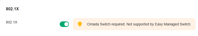
Step 2: Configure RADIUS Profile and Parameters
Select the RADIUS profile you have created. If no RADIUS profiles have been created, click Create New RADIUS Profile from the drop-down list or Manage RADIUS Profile to create one. The RADIUS profile records the information of the RADIUS server which acts as the authentication server during 802.1X authentication.

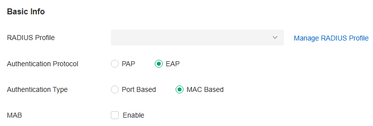
|
Authentication Protocol |
Select the authentication protocol for exchanging messages between the switch and RADIUS server. As a bridge between the client and RADIUS server, the switch forwards messages for them. It uses AP packets to exchange messages with the client, and processes the messages according to the specified authentication protocol before forwarding them to the RADIUS server. PAP: The AP packets are converted to other protocol (such as RADIUS) packets, and transmitted to the RADIUS server. EAP: The AP packets are encapsulated in other protocol (such as RADIUS) packets, and transmitted to the authentication server. To use this authentication mechanism, the RADIUS server should support AP attributes. |
|---|---|
|
Authentication Type |
Select the 802.1X authentication type. Port Based: After a client connected to the port gets authenticated successfully, other clients can access the network via the port without authentication. MAC Based: Clients connected to the port need to be authenticated individually. The RADIUS server distinguishes clients by their MAC addresses. |
|
VLAN Assignment |
This feature allows the RADIUS server to send the VLAN configurations to the port dynamically. After the port is authenticated, the RADIUS server assigns the VLAN based on the username of the client connecting to the port. The username-to-VLAN mappings must be already stored in the RADIUS server database. This feature is available only when the 802.1X authentication type is Port Based. |
|
MAB |
MAB (MAC Authentication Bypass) allows clients to be authenticated without any client software installed. MAB is useful for authenticating devices without 802.1X capability like IP phones. When MAB is enabled on a port, the switch will learn the MAC address of the client automatically and send the authentication server a RADIUS access request frame with the client’s MAC address as the username and password. MAB takes effect only when 802.1X authentication is enabled on the port. |
Step 3: Select the Ports
Select the ports to enable 802.1X authentication or MAB for them.
To enable 802.1X authentication, click the unselected ports. 802.1X-enabled ports will be marked with  .
.
To enable MAB, click the ports marked with  . MAB-enabled ports will be marked with
 .
.
Note:
You can enable MAB only on 802.1X-enabled ports.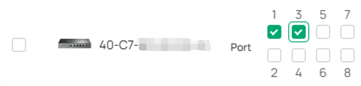
Note:
• You are not recommended to enable 802.1X authentication on the switch ports which connects to network devices without 802.1X capability like the router and APs.
• The switch authenticates wired clients which connect to the port with 802.1X enabled. And the gateway authenticates wired clients which connect to the network with Portal configured. Wired clients should pass Portal and 802.1X authentication to access the internet when both are configured.
Configure 802.1X Authentication
Overview
MAC-Based Authentication allows or disallows clients access to wireless networks based on the MAC addresses of the clients. In this authentication method, the controller takes wireless clients’ MAC addresses as their usernames and passwords for authentication. The RADIUS server authenticates the MAC addresses against its database which stores the allowed MAC addresses. Clients can access the wireless networks configured with MAC-based authentication after passing authentication successfully.
Note:
Both MAC-Based Authentication and Portal authentication can authenticate wireless clients. If both are configured on a wireless network, a wireless client needs to pass MAC-Based Authentication first and then Portal authentication for internet access. You can enable MAC-Based Authentication Fallback to allow clients bypass MAC-Based Authentication, which means the client needs to pass either of the two authentication. The client tries MAC-Based Authentication first, and is allowed to try portal authentication if it failed the MAC-Based Authentication.
Configuration
1. Launch the controller and access a site.
2. Go to Network Config > Authentication > MAC-Based Authentication. Click to enable MAC-Based Authentication.

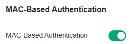
3. In the Basic Info, select the SSIDs, RADIUS Profile and other required parameters. Refer to the following table to configure the required parameters and click Apply.

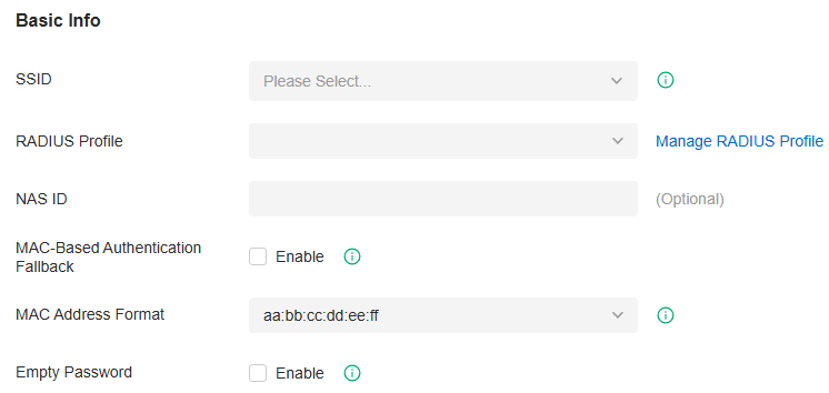
|
SSID |
Select one or more SSIDs for MAC-based authentication to take effect. |
|---|---|
|
RADIUS Profile |
Select the RADIUS profile you have created. If no RADIUS profiles have been created, click Create New RADIUS Profile from the drop-down list or Manage RADIUS Profile to create one. The RADIUS profile records the information of the RADIUS server which acts as the authentication server during MAC-Based Authentication. |
|
NAS ID |
Configure a Network Access Server Identifier (NAS ID) for the authentication. Authentication request packets from the controller to the RADIUS server carry the NAS ID. The RADIUS server can classify users into different groups based on the NAS ID, and then choose different policies for different groups. |
|
MAC-Based Authentication Fallback |
For the wireless network configured with both MAC-Based Authentication and Portal, if you enable this feature, a wireless client needs to pass only one authentication. The client tries MAC-Based Authentication first, and is allowed to try Portal authentication if it failed the MAC-Based Authentication. If you disable this feature as default, a wireless client needs to pass both the MAC-Based Authentication and portal authentication for internet access, and will be denied if it fails either of the authentication. |
|
MAC Address Format |
Select clients’ MAC address format which the controller uses for authentication. Then configure the MAC addresses in the specified format as usernames for the clients on the RADIUS server. |
|
Empty Password |
Click to allow a blank password for MAC-Based Authentication. With this option disabled, the password will be the same as the username. |
Configuring VPN Networks
VPN (Virtual Private Network) provides a means for secure communication between remote computers across a public wide area network (WAN), such as the internet. The gateways supports various VPN types. This chapter guides you on how to configure VPN networks with the Omada Controller.
VPN Overview
VPN (Virtual Private Network) gives remote LANs or users secure access to LAN resources over a public network such as the internet. Virtual indicates the VPN connection is based on the logical end-to-end connection instead of the physical end-to-end connection. Private indicates users can establish the VPN connection according to their requirements and only specific users are allowed to use the VPN connection.
The core of VPN connection is to realize tunnel communication, which fulfills the task of data encapsulation, data transmission and data decompression via the tunneling protocol. The gateway supports common tunneling protocols that a VPN uses to keep the data secure:
■ IPsec
IPsec (IP Security) can provide security services such as data confidentiality, data integrity and data authentication at the IP layer. IPsec uses IKE (Internet Key Exchange) to handle negotiation of protocols and algorithms based on the user-specified policy, and to generate the encryption and authentication keys to be used by IPsec. IPsec can be used to protect one or more paths between a pair of hosts, between a pair of security gateways, or between a security gateway and a host.
■ PPTP
PPTP (Point-to-Point Tunneling Protocol) is a network protocol that enables the secure transfer of data from a remote client to a private enterprise server by creating a VPN across TCP/IP-based data networks. PPTP uses the username and password to validate users.
■ L2TP
L2TP (Layer 2 Tunneling Protocol) provides a way for a dialup user to make a virtual Point-to-Point Protocol (PPP) connection to an L2TP network server (LNS), which can be a security gateway. L2TP sends PPP frames through a tunnel between an L2TP access concentrator (LAC) and the LNS. Because of the lack of confidentiality inherent in the L2TP protocol, it is often implemented along with IPsec. L2TP uses the username and password to validate users.
■ OpenVPN
OpenVPN uses OpenSSL for encryption of UDP and TCP for traffic transmission. OpenVPN uses a client-server connection to provide secure communications between a server and a remote client over the internet. One of the most important steps in setting up OpenVPN is obtaining a certificate which is used for authentication. The controller supports generating the certificate which can be downloaded as a file on your computer. With the certificate imported, the remote clients are checked out by the certificate and granted access to the LAN resources.
There are many variations of virtual private networks, with the majority based on two main models:
■ Site-to-Site VPN
A Site-to-Site VPN creates a connection between two networks at different geographic locations. Typically, headquarters set up Site-to-Site VPN with the subsidiary to provide the branch office with access to the headquarters' network.
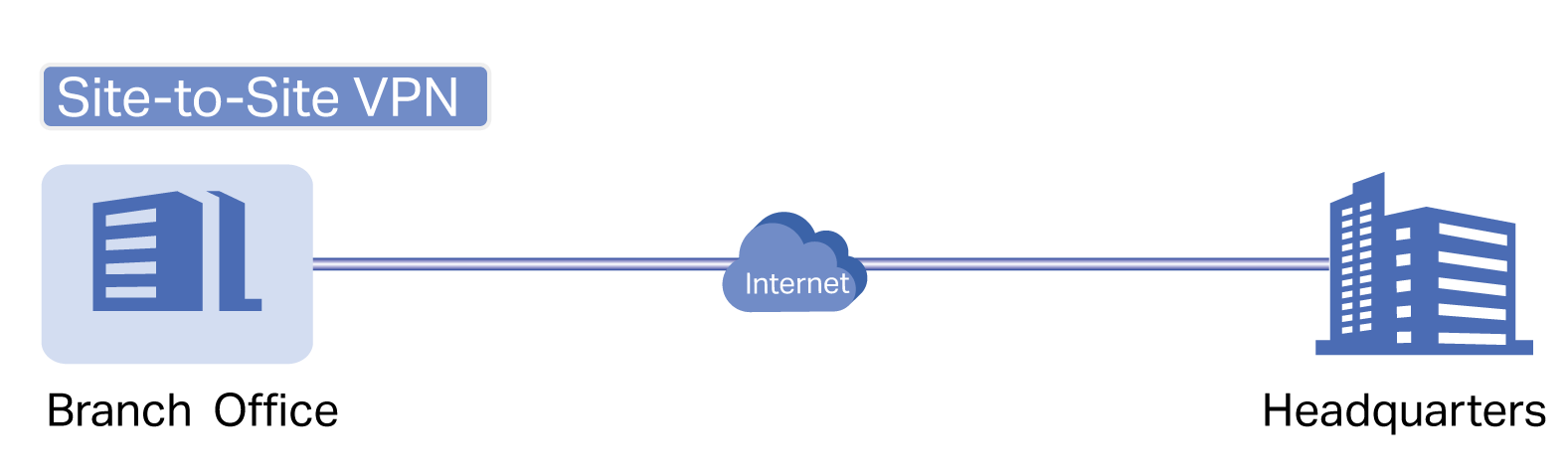
The gateway supports two types of Site-to-Site VPNs:
• Auto IPsec
The controller automatically creates an IPsec VPN tunnel between two sites on the same controller. The VPN connection is bidirectional. That is, creating an Auto IPsec VPN from site A to site B also provides connectivity from site B to site A, and nothing is needed to be configured on site B.
• Manual IPsec
You create an IPsec VPN tunnel between two peer routers over internet manually, from a local router to a remote router that supports IPsec. The gateway on this site is the local peer router.
■ Client-to-Site VPN
A Client-to-Site VPN creates a connection to the LAN from a remote host. It is useful for teleworkers and business travelers to access their central LAN from a remote location without compromising privacy and security.
The first step to build a Client-to-Site VPN connection is to determine the role of the gateways and which VPN tunneling protocol to use:
• VPN Server
The gateway on the central LAN works as a VPN server to provide a remote host with access to the local network. The gateway which functions as a VPN server can use L2TP, PPTP, IPsec, or OpenVPN as the tunneling protocol.
• VPN Client
Either the remote user's gateway or the remote user's laptop or PC works as the VPN client.
When the remote user's gateway works as the VPN client, the gateway helps create VPN tunnels between its connected hosts and the VPN server. The gateway which functions as a VPN client can use L2TP, PPTP, or OpenVPN as the tunneling protocol.

When the remote user's laptop or PC works as the VPN client, the laptop or PC uses a VPN client software program to create VPN tunnels between itself and the VPN server. The VPN client software program can use L2TP, PPTP, IPsec, or OpenVPN as the tunneling protocol.
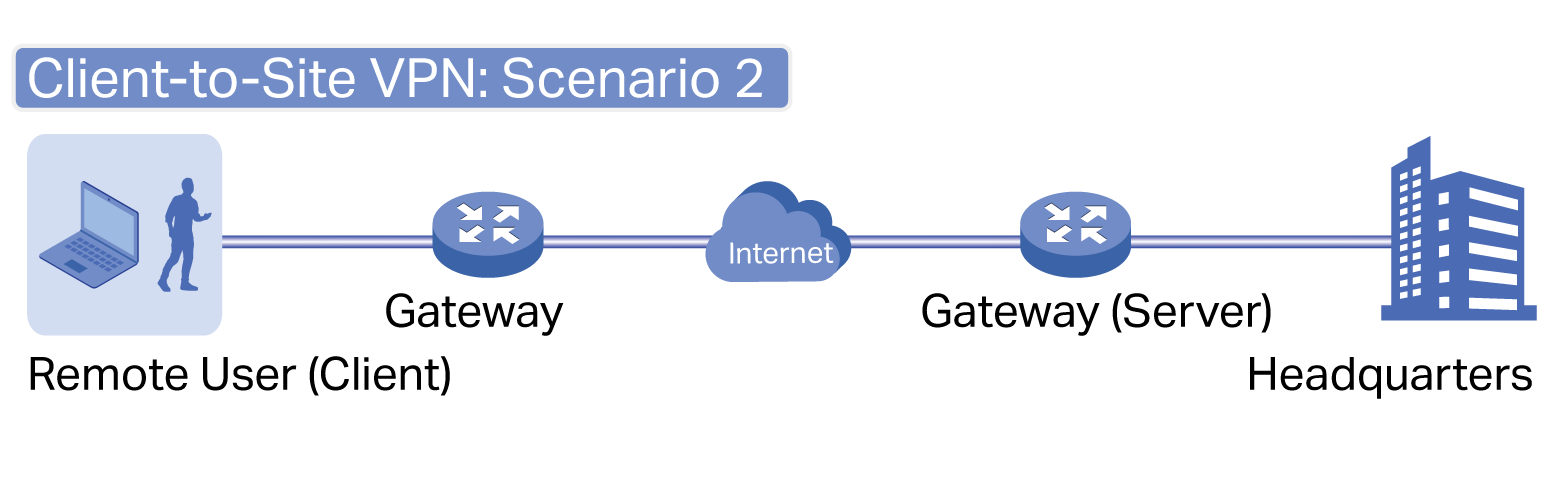
 Note:
Note:
In scenario 1, you need to configure VPN client and VPN server separately on the gateways, while remote hosts can access the local networks without running VPN client software.
In scenario 2, you need to configure VPN server on the gateway, and then configure the VPN client software program on the remote user's laptop or PC, while the remote user's gateway doesn't need any VPN configuration.
Here is the infographic to provide a quick overview of VPN solutions.
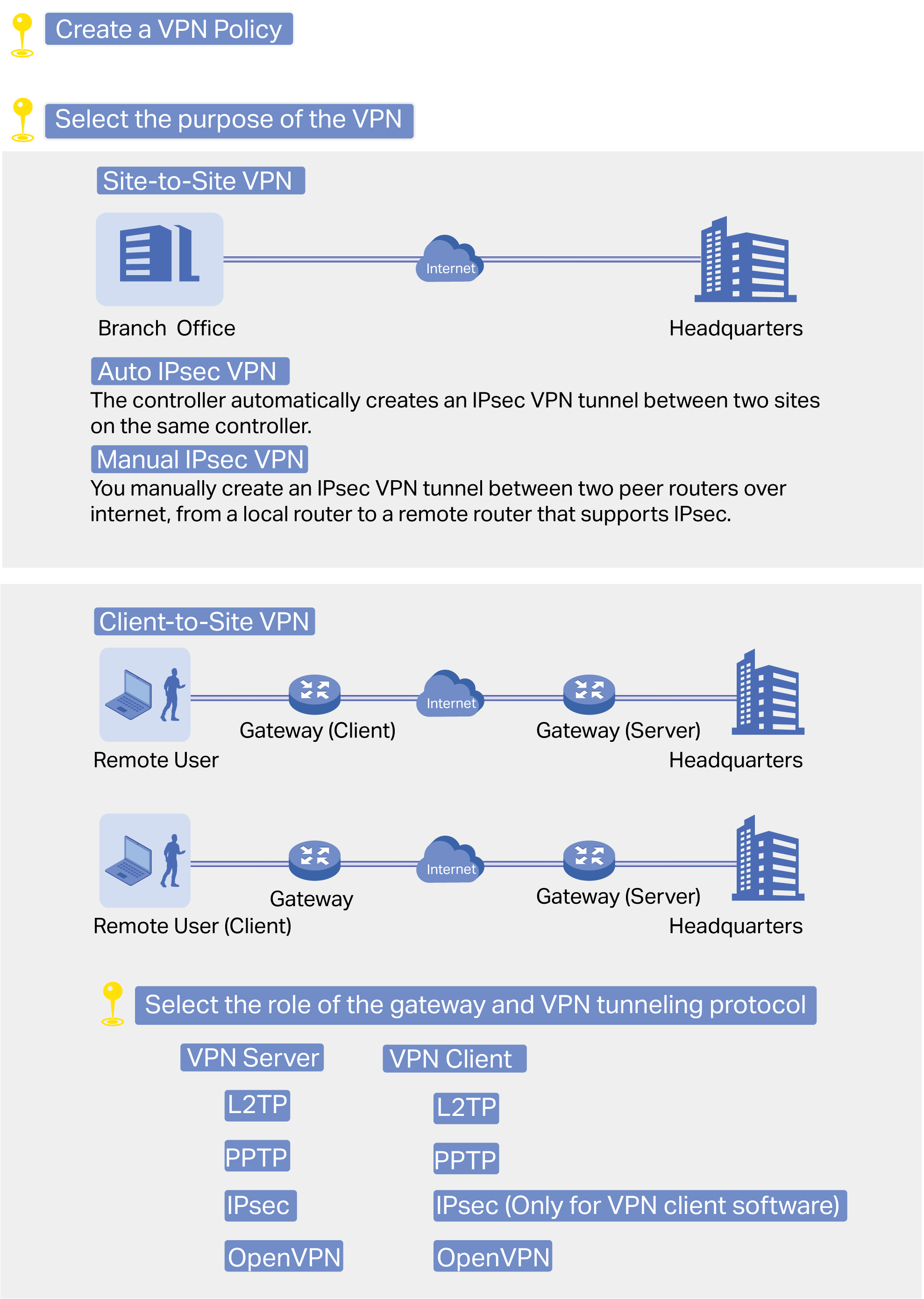
Configure the Site-to-Site VPN
To complete the VPN configuration, follow these steps:
1) Create a new VPN policy and select the purpose of the VPN according to your needs. Select Site-to-Site if you want the network connected to another. Select Client-to-Site if you want some hosts connected to the network.
2) Select the VPN tunneling protocol and configure the VPN policy based on the protocol.
The gateway supports two types of Site-to-Site VPNs: Auto IPsec and Manual IPsec.
Configuring Auto IPsec VPN
1. Launch the controller and access a site.
2. Go to Network Config > VPN > VPN. Click Create New VPN Policy to load the following page.
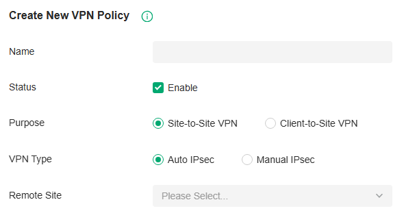
3. Enter a name to identify the VPN policy and select the purpose as Site-to-Site VPN. Refer to the following table to configure the required parameters and click Create.
|
Name |
Enter a name to identify the VPN policy. |
|---|---|
|
Status |
Click the checkbox to enable the VPN policy. |
|
Purpose |
Select the purpose for the VPN as Site-to-Site VPN. |
|
VPN Type |
Select the VPN type as Auto IPsec. With Auto IPsec, the controller automatically creates an IPsec VPN tunnel between two sites on the same controller. The VPN connection is bidirectional. That is, creating an Auto IPsec VPN from site A to site B also provides connectivity from site B to site A, and nothing is needed to be configured on site B. |
|
Remote Site |
Select the site on the other end of the Auto IPsec VPN tunnel. Make sure that the selected remote site has an Omada managed gateway within the same controller. |
Configuring Manual IPsec VPN
1. Launch the controller and access a site.
2. Go to Network Config > VPN > VPN. Click Create New VPN Policy to load the following page.
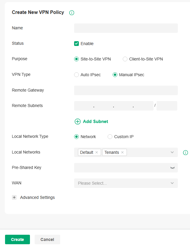
 3. Enter a name to identify the VPN policy and select the purpose as Site-to-Site VPN. Refer to the following table to configure the basic parameters and click Create.
|
Name |
Enter a name to identify the VPN policy. |
|---|---|
|
Status |
Click the checkbox to enable the VPN policy. |
|
Purpose |
Select the purpose for the VPN as Site-to-Site VPN. |
|
VPN Type |
Select the VPN type as Manual IPsec. |
|
Remote Gateway |
Enter an IP address or a domain name as the gateway on the remote peer of the VPN tunnel. |
|
Remote Subnets |
Enter the IP address range of LAN on the remote peer of the VPN tunnel. Remote subnets should not be in the same network segment as the local LAN. |
|
Local Network Type |
Specify whether to apply the VPN policy to specific local networks or IP addresses. Network: Specify the local networks of the VPN tunnel. The VPN policy will be only applied to the selected local networks. Custom IP: Specify the IP addresses of the VPN tunnel. The VPN policy will be only applied to the specified IP addresses. |
|
Pre-Shared Key |
Enter the pre-shared key(PSK). Both peer gateways must use the same pre-shared secret key for authentication. A pre-shared key is a string of characters that is used as an authentication key. Both peer gateways create a hash value based on the same pre-shared key and other information. The hash values are then exchanged and verified to authenticate the other party. The pre-shared keys should be long and random for security. Short or predictable pre-shared keys can be easily broken in brute-force attacks. To maintain a high level of security, administrators are recommended to update the pre-shared key periodically. |
|
WAN |
Select the WAN port on which the IPsec VPN tunnel is established. |
4.Click Advanced Settings to load the following page.

Advanced settings include Phase-1 settings and Phase-2 settings. Phase-1 is used to set up a secure encrypted channel which the two peers can negotiate Phase-2, and then establish the IKE Security Associations (IKE SA). Phase-2 is used to negotiate about a set of parameters that define what traffic can go through the VPN, and how to encrypt and authenticate the traffic, then establish the IPsec Security Associations (IPsec SA).
Refer to the following table to complete the configurations according to your actual needs and click Create.
For Phase-1 Settings:
|
Phase-1 Settings |
The IKE version you select determines the available Phase-1 settings and defines the negotiation process . Both VPN gateways must be configured to use the same IKE version and Phase-1 settings. |
|---|---|
|
Internet Key Exchange Version |
Select the version of Internet Key Exchange (IKE) protocol which is used to set up security associations for IPsec. Both IKEv1 and IKEv2 are supported with gateways, but IKEv1 is available only when the VPN policy is applied to a single Remote Subnet and a single Local Network. Note that both peer gateways must be configured to use the same IKE version. |
|
Proposal |
Specify the proposal for IKE negotiation phase-1. An IKE proposal lists the encryption algorithm, authentication algorithm and Diffie-Hellman (DH) groups to be negotiated with the remote IPsec peer. Authentication algorithms verify the data integrity and authenticity of a message. Encryption algorithms protect the data from being read by a third-party. Diffie-Hellman (DH) groups determine the strength of the key used in the key exchange process. Note that both peer gateways must be configured to use the same Proposal. |
|
Exchange Mode |
Specify the IKE Exchange Mode when IKEv1 is selected. Main Mode: This mode provides identity protection and exchanges more information, which applies to scenarios with higher requirements for identity protection. Aggressive Mode: This mode establishes a faster connection but with lower security, which applies to scenarios with lower requirements for identity protection. |
|
Negotiation Mode |
Specify the IKE Negotiation Mode as Initiator Mode or Responder Mode. Initiator Mode: This mode means that the local device initiates a connection to the peer. Responder Mode: This mode means that the local device waits for the connection request initiated by the peer. |
|
Local ID Type |
Specify the type of Local ID which indicates the authentication identifier sent to the peer for IKE negotiation. IP Address: Select IP Address to use the IP address for authentication. Name: Select Name, and then enter the name in the Local ID field to use the name as the ID for authentication. Note that the type and value of Local ID should be the same as Remote ID given for the remote peer of the VPN tunnel. |
|
Local ID |
When the Local ID Type is configured as Name, enter a name for the local device as the ID in IKE negotiation. The name should be in the format of FQDN (Fully Qualified Domain Name). |
|
Remote ID Type |
Specify the type of Remote ID which indicates the authentication identifier received from the peer for IKE negotiation. IP Address: Select IP Address to use the IP address for authentication. Name: Select Name, and then enter the name in the Remote ID field to use the name as the ID for authentication. Note that the type and value of Remote ID should be the same as Local ID given for the remote peer of the VPN tunnel. |
|
Remote ID |
When the Remote ID Type is configured as Name, enter a name of the remote peer as the ID in IKE negotiation. The name should be in the format of FQDN (Fully Qualified Domain Name). |
|
SA Lifetime |
Specify ISAKMP SA (Security Association) Lifetime in IKE negotiation. If the SA lifetime expired, the related ISAKMP SA will be deleted. |
|
DPD |
Check the box to enable DPD (Dead Peer Detect) function. If enabled, the IKE endpoint can send a DPD request to the peer to inspect whether the IKE peer is alive. |
|
DPD Interval |
Specify the interval between sending DPD requests with DPD enabled. If the IKE endpoint receives a response from the peer during this interval, it considers the peer alive. If the IKE endpoint does not receive a response during the interval, it considers the peer dead and deletes the SA. |
For Phase-2 Settings:
|
Phase-2 Settings |
The purpose of Phase 2 negotiations is to establish the Phase-2 SA (also called the IPsec SA). The IPsec SA is a set of traffic specifications that tell the device what traffic to send over the VPN, and how to encrypt and authenticate that traffic. |
|---|---|
|
Encapsulation Mode |
Specify the Encapsulation Mode as Tunnel Mode or Transport Mode. When both ends of the tunnel are hosts, either mode can be chosen. When at least one of the endpoints of a tunnel is a security gateway, such as a router or firewall, Tunnel Mode is recommended to ensure safety. |
|
Proposal |
Specify the proposal for IKE negotiation phase-2. An IPsec proposal lists the encryption algorithm, authentication algorithm and protocol to be negotiated with the remote IPsec peer. Note that both peer gateways must be configured to use the same Proposal. |
|
PFS |
Select the DH group to enable PFS (Perfect Forward Security) for IKE mode, then the key generated in phase-2 will be irrelevant with the key in phase-1, which enhance the network security. With None selected, it means PFS is disabled and the key in phase-2 will be generated based on the key in phase-1. |
|
SA Lifetime |
Specify IPsec SA (Security Association) Lifetime in IKE negotiation. If the SA lifetime expired, the related IPsec SA will be deleted. |
Configure the Client-to-Site VPN
To complete the VPN configuration, follow these steps:
1) Create a new VPN policy and select the purpose of the VPN according to your needs. Select Site-to-Site if you want the network connected to another. Select Client-to-Site if you want some hosts connected to the network.
2) Select the VPN tunneling protocol and configure the VPN policy based on the protocol.
The gateway supports seven types of client-to-Site VPNs depending on the role of your gateway and the protocol that you used:
Configuring the gateway as a VPN server using L2TP
Configuring the gateway as a VPN server using PPTP
Configuring the gateway as a VPN server using IPsec
Configuring the gateway as a VPN server using OpenVPN
Configuring the gateway as a VPN client using L2TP
Configuring the gateway as a VPN client using PPTP
Configuring the gateway as a VPN client using OpenVPN
Configuring the gateway as a VPN server using L2TP
1. Launch the controller and access a site.
2. Go to Network Config > VPN > VPN. Click Create New VPN Policy to load the following page.
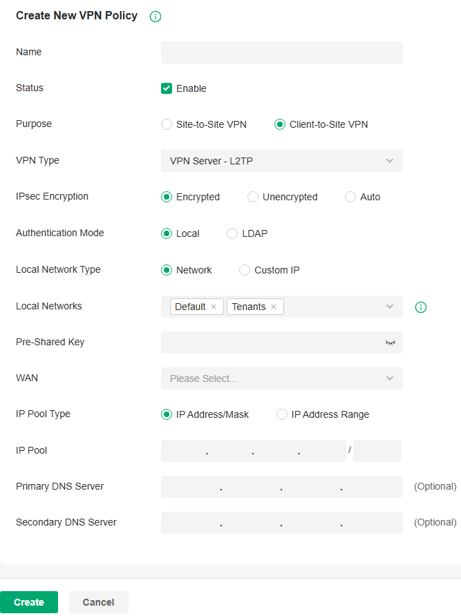
3. Enter a name to identify the VPN policy and select the purpose as Client-to-Site VPN. Refer to the following table to configure the required parameters and click Create.
|
Name |
Enter a name to identify the VPN policy. |
|---|---|
|
Status |
Click the checkbox to enable the VPN policy. |
|
Purpose |
Select the purpose for the VPN as Client-to-Site VPN. |
|
VPN Type |
Select the VPN type as VPN Server - L2TP. |
|
IPsec Encryption |
Specify whether to enable the encryption for the tunnel. Encrypted: Select Encrypted to encrypt the L2TP tunnel by IPsec (L2TP over IPsec). With Encrypted selected, enter the Pre-shared Key for IKE authentication. VPN server and VPN client must use the same pre-shared secret key for authentication. Unencrypted: With Unencrypted selected, the L2TP tunnel will not be encrypted by IPsec. Auto: With Auto selected, the L2TP server will determine whether to encrypt the tunnel according to the client ‘s encryption settings. And enter the Pre-shared Key for IKE authentication. VPN server and VPN client must use the same pre-shared secret key for authentication. |
|
Authentication Mode |
Select the authentication mode: Local or LDAP. |
|
Local Network Type |
Specify whether to apply the VPN policy to specific local networks or IP addresses. Network: Specify the local networks of the VPN tunnel. The VPN policy will be only applied to the selected local networks. Custom IP: Specify the IP addresses of the VPN tunnel. The VPN policy will be only applied to the specified IP addresses. |
|
Pre-shared Key |
Enter the pre-shared secret key when IPsec Encryption is selected as Encrypted and Auto. Both peer routers must use the same pre-shared secret key for authentication. |
|
WAN |
Select the WAN port on which the L2TP VPN tunnel is established. Each WAN port supports only one L2TP VPN tunnel when the gateway works as a L2TP server. |
|
IP Pool Type |
Specify the format of the IP pool. |
|
IP Pool |
If you selected IP Address/Mask type, enter the IP address and subnet mask to decide the range of the VPN IP pool. If you select IP Address Range type, enter the start and end IP addresses of the VPN IP pool. |
|
Primary DNS Server |
Enter the IP address of the primary DNS server provided by your ISP. |
|
Secondary DNS Server |
(Optional) Enter the IP address of the secondary DNS server, which provides redundancy in case the primary DNS server goes down. |
4. Add the VPN users account to validate remote hosts. To create VPN users, refer to Configure VPN Users.
Configuring the gateway as a VPN server using PPTP
1. Launch the controller and access a site.
2. Go to Network Config > VPN > VPN. Click Create New VPN Policy to load the following page.
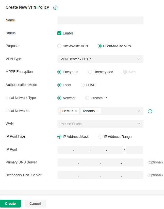
3. Enter a name to identify the VPN policy and select the purpose as Client-to-Site VPN. Refer to the following table to configure the required parameters and click Create.
|
Name |
Enter a name to identify the VPN policy. |
|---|---|
|
Status |
Click the checkbox to enable the VPN policy. |
|
Purpose |
Select the purpose for the VPN as Client-to-Site VPN. |
|
VPN Type |
Select the VPN type as VPN Server - PPTP. |
|
MPPE Encryption |
Specify whether to enable MPPE (Microsoft Point-to-Point Encryption) for the tunnel. Encrypted: With Encrypted selected, the PPTP tunnel will be encrypted by MPPE. Unencrypted: With Unencrypted selected, the PPTP tunnel will be not encrypted by MPPE. |
|
Authentication Mode |
Select the authentication mode: Local or LDAP. |
|
Local Network Type |
Specify whether to apply the VPN policy to specific local networks or IP addresses. Network: Specify the local networks of the VPN tunnel. The VPN policy will be only applied to the selected local networks. Custom IP: Specify the IP addresses of the VPN tunnel. The VPN policy will be only applied to the specified IP addresses. |
|
WAN |
Select the WAN port on which the PPTP VPN tunnel is established. Each WAN port supports only one PPTP VPN tunnel when the gateway works as a PPTP server. |
|
IP Pool Type |
Specify the format of the IP pool. |
|
IP Pool |
If you selected IP Address/Mask type, enter the IP address and subnet mask to decide the range of the VPN IP pool. If you select IP Address Range type, enter the start and end IP addresses of the VPN IP pool. |
|
Primary DNS Server |
Enter the IP address of the primary DNS server provided by your ISP. |
|
Secondary DNS Server |
(Optional) Enter the IP address of the secondary DNS server, which provides redundancy in case the primary DNS server goes down. |
4. Add the VPN users account to validate remote hosts. To create VPN users, refer to Configure VPN Users.
Configuring the gateway as a VPN server using IPsec
1. Launch the controller and access a site.
2. Go to Network Config > VPN > VPN. Click Create New VPN Policy to load the following page.
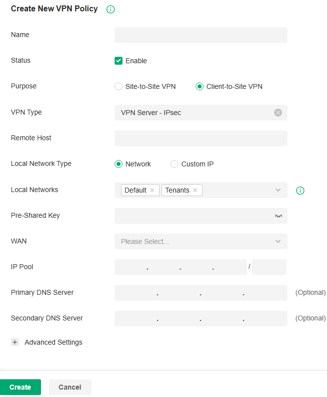
3. Enter a name to identify the VPN policy and select the purpose as Client-to-Site VPN. Refer to the following table to configure the basic parameters and click Create.
|
Name |
Enter a name to identify the VPN policy. |
|---|---|
|
Status |
Click the checkbox to enable the VPN policy. |
|
Purpose |
Select the purpose for the VPN as Client-to-Site VPN. |
|
VPN Type |
Select the VPN type as VPN Server - IPsec. |
|
Remote Host |
Enter an IP address or a domain name of the host on the remote peer of the VPN tunnel. 0.0.0.0 represents any IP address. |
|
Local Network Type |
Specify whether to apply the VPN policy to specific local networks or IP addresses. Network: Specify the local networks of the VPN tunnel. The VPN policy will be only applied to the selected local networks. Custom IP: Specify the IP addresses of the VPN tunnel. The VPN policy will be only applied to the specified IP addresses. |
|
Pre-Shared Key |
Enter the pre-shared key(PSK). Both peer gateways must use the same pre-shared secret key for authentication. A pre-shared key is a string of characters that is used as an authentication key. Both VPN peers create a hash value based on the same pre-shared key and other information. The hash values are then exchanged and verified to authenticate the other party. The pre-shared keys should be long and random for security. Short or predictable pre-shared keys can be easily broken in brute-force attacks. To maintain a high level of security, administrators are recommended to update the pre-shared key periodically. |
|
WAN |
Select the WAN port on which the IPsec VPN tunnel is established. |
|
IP Pool |
Enter the IP address and subnet mask to decide the range of the VPN IP pool. The VPN server will assign IP address to the remote host when the tunnel is established. You can specify any reasonable IP address that will not cause overlap with the IP address of the LAN on the local peer router. |
|
Primary DNS Server |
Enter the IP address of the primary DNS server provided by your ISP. |
|
Secondary DNS Server |
(Optional) Enter the IP address of the secondary DNS server, which provides redundancy in case the primary DNS server goes down. |
4. Click Advanced Settings to load the following page.
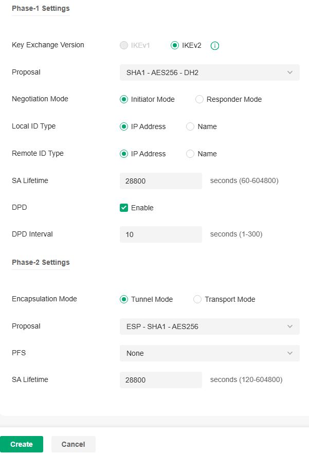
Advanced settings include Phase-1 settings and Phase-2 settings. Phase-1 is used to set up a secure encrypted channel which the two peers can negotiate Phase-2, and then establish the IKE Security Associations (IKE SA). Phase-2 is used to negotiate about a set of parameters that define what traffic can go through the VPN, and how to encrypt and authenticate the traffic, then establish the IPsec Security Associations (IPsec SA).
Refer to the following table to complete the configurations according to your actual needs and click Create.
For Phase-1 Settings:
|
Phase-1 Settings |
The IKE version you select determines the available Phase-1 settings and defines the negotiation process . Both VPN gateways must be configured to use the same IKE version and Phase-1 settings. |
|---|---|
|
Internet Key Exchange Version |
Select the version of Internet Key Exchange (IKE) protocol which is used to set up security associations for IPsec. Both IKEv1 and IKEv2 are supported with gateways, but IKEv1 is available only when the VPN policy is applied to a single Remote Subnet and a single Local Network. Note that both VPN peers must be configured to use the same IKE version. |
|
Proposal |
Specify the proposal for IKE negotiation phase-1. An IKE proposal lists the encryption algorithm, authentication algorithm and Diffie-Hellman (DH) groups to be negotiated with the remote IPsec peer. Authentication algorithms verify the data integrity and authenticity of a message. Encryption algorithms protect the data from being read by a third-party. Diffie-Hellman (DH) groups determine the strength of the key used in the key exchange process. Note that both VPN peers must be configured to use the same Proposal. |
|
Exchange Mode |
Specify the IKE Exchange Mode when IKEv1 is selected. Main Mode: This mode provides identity protection and exchanges more information, which applies to scenarios with higher requirements for identity protection. Aggressive Mode: This mode establishes a faster connection but with lower security, which applies to scenarios with lower requirements for identity protection. |
|
Negotiation Mode |
Specify the IKE Negotiation Mode as Initiator Mode or Responder Mode. Initiator Mode: This mode means that the local device initiates a connection to the peer. Responder Mode: This mode means that the local device waits for the connection request initiated by the peer. |
|
Local ID Type |
Specify the type of Local ID which indicates the authentication identifier sent to the peer for IKE negotiation. IP Address: Select IP Address to use the IP address for authentication. Name: Select Name, and then enter the name in the Local ID field to use the name as the ID for authentication. Note that the type and value of Local ID should be the same as Remote ID given for the remote peer of the VPN tunnel. |
|
Local ID |
When the Local ID Type is configured as Name, enter a name for the local device as the ID in IKE negotiation. The name should be in the format of FQDN (Fully Qualified Domain Name). |
|
Remote ID Type |
Specify the type of Remote ID which indicates the authentication identifier received from the peer for IKE negotiation. IP Address: Select IP Address to use the IP address for authentication. Name: Select Name, and then enter the name in the Remote ID field to use the name as the ID for authentication. Note that the type and value of Remote ID should be the same as Local ID given for the remote peer of the VPN tunnel. |
|
Remote ID |
When the Remote ID Type is configured as Name, enter a name of the remote peer as the ID in IKE negotiation. The name should be in the format of FQDN (Fully Qualified Domain Name). |
|
SA Lifetime |
Specify ISAKMP SA (Security Association) Lifetime in IKE negotiation. If the SA lifetime expired, the related ISAKMP SA will be deleted. |
|
DPD |
Check the box to enable DPD (Dead Peer Detect) function. If enabled, the IKE endpoint can send a DPD request to the peer to inspect whether the IKE peer is alive. |
|
DPD Interval |
Specify the interval between sending DPD requests with DPD enabled. If the IKE endpoint receives a response from the peer during this interval, it considers the peer alive. If the IKE endpoint does not receive a response during the interval, it considers the peer dead and deletes the SA. |
For Phase-2 Settings:
|
Phase-2 Settings |
The purpose of Phase 2 negotiations is to establish the Phase-2 SA (also called the IPsec SA). The IPsec SA is a set of traffic specifications that tell the device what traffic to send over the VPN, and how to encrypt and authenticate that traffic. |
|---|---|
|
Encapsulation Mode |
Specify the Encapsulation Mode as Tunnel Mode or Transport Mode. When both ends of the tunnel are hosts, either mode can be chosen. When at least one of the endpoints of a tunnel is a security gateway, such as a router or firewall, Tunnel Mode is recommended to ensure safety. |
|
Proposal |
Specify the proposal for IKE negotiation phase-2. An IPsec proposal lists the encryption algorithm, authentication algorithm and protocol to be negotiated with the remote IPsec peer. Note that both peer gateways must be configured to use the same Proposal. |
|
PFS |
Select the DH group to enable PFS (Perfect Forward Security) for IKE mode, then the key generated in phase-2 will be irrelevant with the key in phase-1, which enhance the network security. With None selected, it means PFS is disabled and the key in phase-2 will be generated based on the key in phase-1. |
|
SA Lifetime |
Specify IPsec SA (Security Association) Lifetime in IKE negotiation. If the SA lifetime expired, the related IPsec SA will be deleted. |
Configuring the gateway as a VPN server using OpenVPN
1. Launch the controller and access a site.
2. Go to Network Config > VPN > VPN. Click Create New VPN Policy to load the following page.
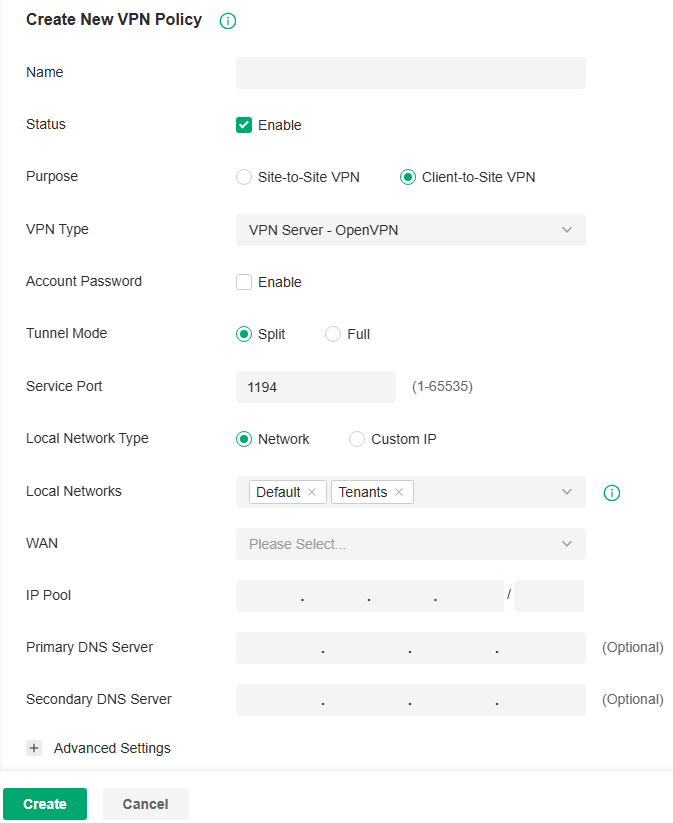
3. Enter a name to identify the VPN policy and select the purpose as Client-to-Site VPN. Refer to the following table to configure the required parameters and click Create.
|
Name |
Enter a name to identify the VPN policy. |
|---|---|
|
Status |
Click the checkbox to enable the VPN policy. |
|
Purpose |
Select the purpose for the VPN as Client-to-Site VPN. |
|
VPN Type |
Select the VPN type as VPN Server - OpenVPN. |
|
Account Password |
Specify whether VPN clients need to enter a user account to access the VPN tunnel. When enabled, you need to create accounts on the VPN User page. |
|
Tunnel Mode |
Select the tunnel mode: Split or Full. Full tunneling uses the VPN for all your traffic, whereas split tunneling sends part of your traffic through a VPN and part of it through the open network. Full tunneling is more secure than split tunneling. |
|
Service Port |
Enter a VPN service port to which a VPN device connects. |
|
Local Network Type |
Specify whether to apply the VPN policy to specific local networks or IP addresses. Network: Specify the local networks of the VPN tunnel. The VPN policy will be only applied to the selected local networks. Custom IP: Specify the IP addresses of the VPN tunnel. The VPN policy will be only applied to the specified IP addresses. |
|
WAN |
Select the WAN port on which the VPN tunnel is established. Each WAN port supports only one OpenVPN tunnel when the gateway works as a OpenVPN server. |
|
IP Pool |
Enter the IP address and subnet mask to decide the range of the VPN IP pool. The VPN server will assign IP address to the remote host when the tunnel is established. You can specify any reasonable IP address that will not cause overlap with the IP address of the LAN on the local peer router. |
|
Primary DNS Server |
Enter the IP address of the primary DNS server provided by your ISP. |
|
Secondary DNS Server |
(Optional) Enter the IP address of the secondary DNS server, which provides redundancy in case the primary DNS server goes down. |
|
Change UDP Protocol to TCP |
Enable this option so the OpenVPN protocol will switch from the default UDP protocol to the TCP protocol. |
4. After clicking Create to save the VPN policy, go to VPN Policy List and click the export icon in the Action column to export the OpenVPN file that ends in .ovpn which is to be used by the remote client. The exported OpenVPN file contains the certificate and configuration information.

Configuring the gateway as a VPN client using L2TP
1. Launch the controller and access a site.
2. Go to Network Config > VPN > VPN. Click Create New VPN Policy to load the following page.
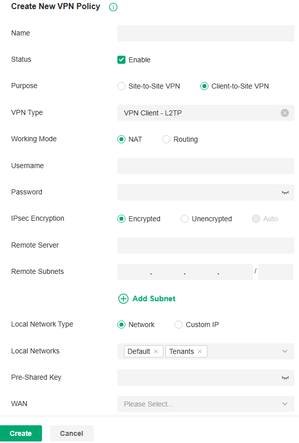
3. Enter a name to identify the VPN policy and select the purpose as Client-to-Site VPN. Refer to the following table to configure the required parameters and click Create.
|
Name |
Enter a name to identify the VPN policy. |
|---|---|
|
Status |
Click the checkbox to enable the VPN policy. |
|
Purpose |
Select the purpose for the VPN as Client-to-Site VPN. |
|
VPN Type |
Select the VPN type as VPN Client - L2TP. |
|
Working Mode |
Specify the Working Mode as NAT or Routing. NAT: With NAT (Network Address Translation) mode selected, the L2TP client uses the assigned IP address as its source addresses of original IP header when forwarding L2TP packets. Routing: With Routing selected, the L2TP client uses its own IP address as its source addresses of original IP header when forwarding L2TP packets. |
|
Username |
Enter the username used for the VPN tunnel. This username should be the same as that of the L2TP server. |
|
Password |
Enter the password of user. This password should be the same as that of the L2TP server. |
|
IPsec Encryption |
Specify whether to enable the encryption for the tunnel. Encrypted: Select Encrypted to encrypt the L2TP tunnel by IPsec (L2TP over IPsec). With Encrypted selected, enter the Pre-shared Key for IKE authentication. VPN server and VPN client must use the same pre-shared secret key for authentication. Unencrypted: With Unencrypted selected, the L2TP tunnel will be not encrypted by IPsec. |
|
Remote Server |
Enter the IP address or domain name of the L2TP server. |
|
Remote Subnets |
Enter the IP address and subnet mask to specify the remote network. It’s always the IP address range of LAN on the remote peer of the VPN tunnel. |
|
Local Network Type |
Specify whether to apply the VPN policy to specific local networks or IP addresses. Network: Specify the local networks of the VPN tunnel. The VPN policy will be only applied to the selected local networks. Custom IP: Specify the IP addresses of the VPN tunnel. The VPN policy will be only applied to the specified IP addresses. |
|
Pre-shared Key |
Enter the pre-shared secret key when the L2TP tunnel is encrypted by IPsec. Both peer gateways must use the same pre-shared secret key for authentication. |
|
WAN |
Select the WAN port on which the VPN tunnel is established. |
Configuring the gateway as a VPN client using PPTP
1. Launch the controller and access a site.
2. Go to Network Config > VPN > VPN. Click Create New VPN Policy to load the following page.
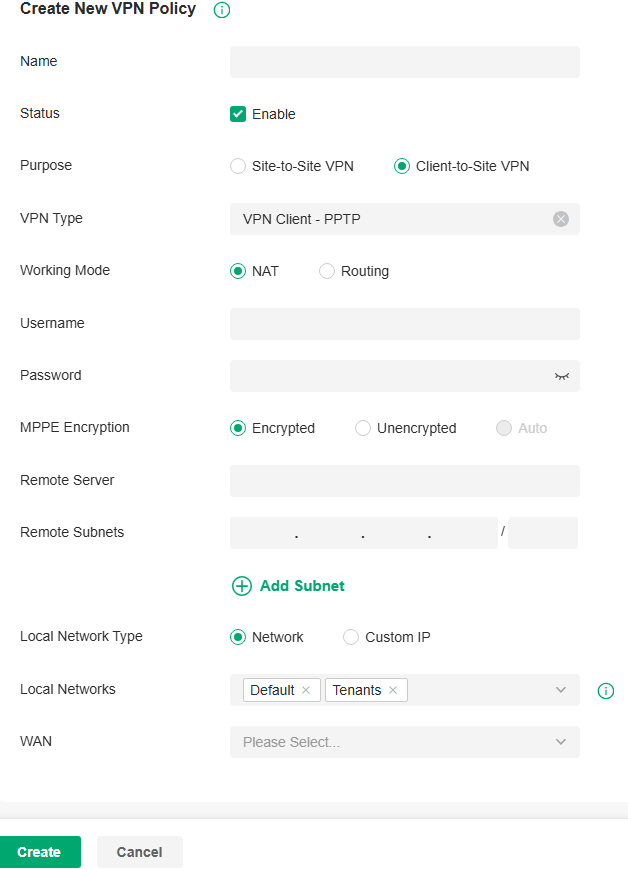
3. Enter a name to identify the VPN policy and select the purpose as Client-to-Site VPN. Refer to the following table to configure the required parameters and click Create.
|
Name |
Enter a name to identify the VPN policy. |
|---|---|
|
Status |
Click the checkbox to enable the VPN policy. |
|
Purpose |
Select the purpose for the VPN as Client-to-Site VPN. |
|
VPN Type |
Select the VPN type as VPN Client - PPTP. |
|
Working Mode |
Specify the Working Mode as NAT or Routing. NAT: With NAT (Network Address Translation) mode selected, the PPTP client uses the assigned IP address as its source addresses of original IP header when forwarding PPTP packets. Routing: With Routing selected, the PPTP client uses its own IP address as its source addresses of original IP header when forwarding PPTP packets. |
|
Username |
Enter the username used for the VPN tunnel. This username should be the same as that of the PPTP server. |
|
Password |
Enter the password of user. This password should be the same as that of the PPTP server. |
|
MPPE Encryption |
Specify whether to enable the encryption for the tunnel. Encrypted: Select Encrypted to encrypt the PPTP tunnel by MPPE. Unencrypted: With Unencrypted selected, the PPTP tunnel will be not encrypted by MPPE. |
|
Remote Server |
Enter the IP address or domain name of the PPTP server. |
|
Remote Subnets |
Enter the IP address and subnet mask to specify the remote network. It’s always the IP address range of LAN on the remote peer of the VPN tunnel. |
|
Local Network Type |
Specify whether to apply the VPN policy to specific local networks or IP addresses. Network: Specify the local networks of the VPN tunnel. The VPN policy will be only applied to the selected local networks. Custom IP: Specify the IP addresses of the VPN tunnel. The VPN policy will be only applied to the specified IP addresses. |
|
WAN |
Select the WAN port on which the VPN tunnel is established. |
Configuring the gateway as a VPN client using OpenVPN
1. Launch the controller and access a site.
2. Go to Network Config > VPN > VPN. Click Create New VPN Policy to load the following page.
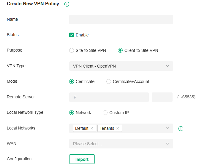
3. Enter a name to identify the VPN policy and select the purpose as Client-to-Site VPN. Refer to the following table to configure the required parameters and click Create.
|
Name |
Enter a name to identify the VPN policy. |
|
Status |
Click the checkbox to enable the VPN policy. |
|
Purpose |
Select the purpose for the VPN as Client-to-Site VPN. |
|
VPN Type |
Select the VPN type as VPN Client - OpenVPN. |
|
Mode |
Select the access mode according to VPN requirements. Certificate: Select this option if the VPN tunnel only requires the certificate. Certificate+Account: Select this option if the VPN tunnel requires the certificate and VPN user account. If selected, configure the following parameters: Username: Enter the username for the VPN tunnel. Password: Enter the password for the VPN tunnel. |
|
Remote Server |
Enter the IP address or domain name of the OpenVPN server. |
|
Local Network Type |
Specify whether to apply the VPN policy to specific local networks or IP addresses. Network: Specify the local networks of the VPN tunnel. The VPN policy will be only applied to the selected local networks. Custom IP: Specify the IP addresses of the VPN tunnel. The VPN policy will be only applied to the specified IP addresses. |
|
WAN |
Select the WAN port on which the VPN tunnel is established. |
|
Configuration |
Click the import icon to import the OpenVPN file that ends in .ovpn generated by the OpenVPN server. Only one file can be imported. If the certificate file and configuration file are generated singly by the OpenVPN server, combine two files and import the whole file. |
Configure VPN Users
Overview
VPN User is used to configure and record your custom settings for VPN configurations, and it allows you to configure VPN users that can be used for multiple VPN servers. It saves you from setting the VPN users with the same configurations repeatedly when you want to apply the user in different VPN servers.
Configuration
To configure the VPN users, follow these steps:
1. Launch the controller and access a site.
2. Go to Network Config > VPN > VPN >VPN User. Click Create New VPN User to add a new entry of VPN User.
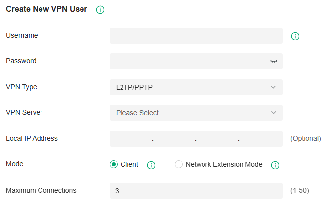
3. Specify the parameters and click Create.
|
Username |
Enter the username used for the VPN tunnel. The client use the username for the validation before accessing the network. |
|---|---|
|
Password |
Enter the password of user. The client uses the password for the validation before accessing the network. |
|
VPN Type |
Select the type for the VPN tunnel. |
|
VPN Server |
Select the VPN Server to connect to. |
|
Local IP Address |
(Optional) Specify the local virtual IP address of the VPN server. Please avoid using the IP address in the DHCP range, which may cause IP confliction, you can enter the LAN IP of the router. |
|
Mode |
Select the Mode for the VPN user entry. Client: This mode allows the client to request for an IP address and the server supplies the IP addresses from the VPN IP Pool. Generally, it is used for the remote host to access the local network. Network Extension Mode: This mode allows clients from the configured subnet to connect to the server and obtain VPN services. Generally, it is used for site-to-site VPN. |
|
Maximum Connections |
In Client mode, set the maximum number of concurrent VPN connections with the same account. |
|
Remote Subnets |
In Network Extension mode, specify the subnet, and clients from specified subnet are allowed to connect to the server. |
If you selected the L2TP/PPTP protocol, specify the following parameters:
|
VPN Server |
Select the VPN server that the VPN user is applied to. |
|---|---|
|
Local IP Address |
(Optional) Specify the local IP address of the VPN tunnel. |
|
Mode |
Specify the connection mode for the VPN users. Client: This mode allows the client to request for an IP address and the server supplies the IP addresses from the VPN IP Pool. With this mode selected, set maximum number of concurrent VPN connections with the same account in Maximum Connections. Network Extension Mode: This mode allows only clients from the configured subnet to connect to the server and obtain VPN services. With this mode selected, specify the subnets in Remote Subnets. |
If you selected the OpenVPN protocol, specify the following parameter:
|
VPN Server |
Select the VPN server that the VPN user is applied to. |
|---|
To edit or delete the VPN users, click the icon in the Action column. You can further filter the entries based on the VPN Server.
Configure IPsec Failover
Overview
IPsec Failover is used to configure the backup group of the IPsec connection. When the primary connection in the group is interrupted, it will try to use the secondary connection to dial up to maintain the stability of the VPN network.
Configuration
1. Launch the controller and access a site.
2. Go to Network Config > VPN > VPN > IPsec Failover. Click Create New IPsec Failover to add a new entry.
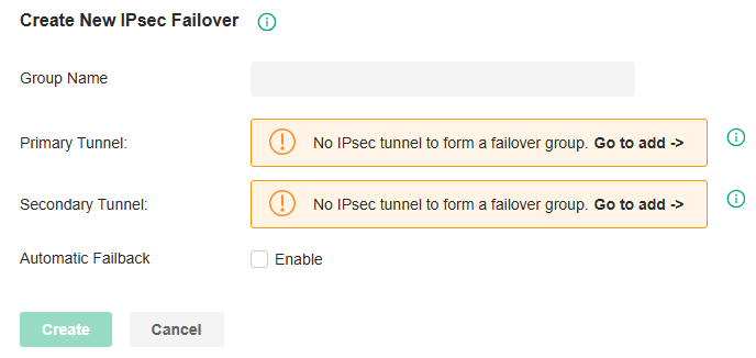
|
Group Name |
Enter a name to identify the IPsec Failover group. |
|---|---|
|
Primary Tunnel |
Specify the IPsec primary connection. |
|
Secondary Tunnel |
Specify the IPsec secondary connection. |
|
Automatic Failback |
Select this function to automatically switch back to the primary connection when it is reachable. When selected, specify the Gateway Failover Timeout time, then the system will query whether the primary connection is reachable within the time, and if yes, it will switch back to the primary connection. |
Configure the SSL VPN
Overview
SSL VPN uses Secure Socket Layer (SSL) to ensure information safety and provides abundant services such as user management, resource management, user lockout, authentication and accounting.
SSL VPN uses username and password for authentication and login. A network administrator can assign different resources to different types of users, and meanwhile associate the users with multiple resources, making it easy to manage and limit the services the users can access through the VPN.
Configuration
■ SSL VPN Server
In SSL VPN Server, you can enable the feature and configure the SSL VPN settings.
1. Launch the controller and access a site.
2. Go to Network Config > VPN > SSL VPN > SSL VPN Server. Enable SSL VPN Server.
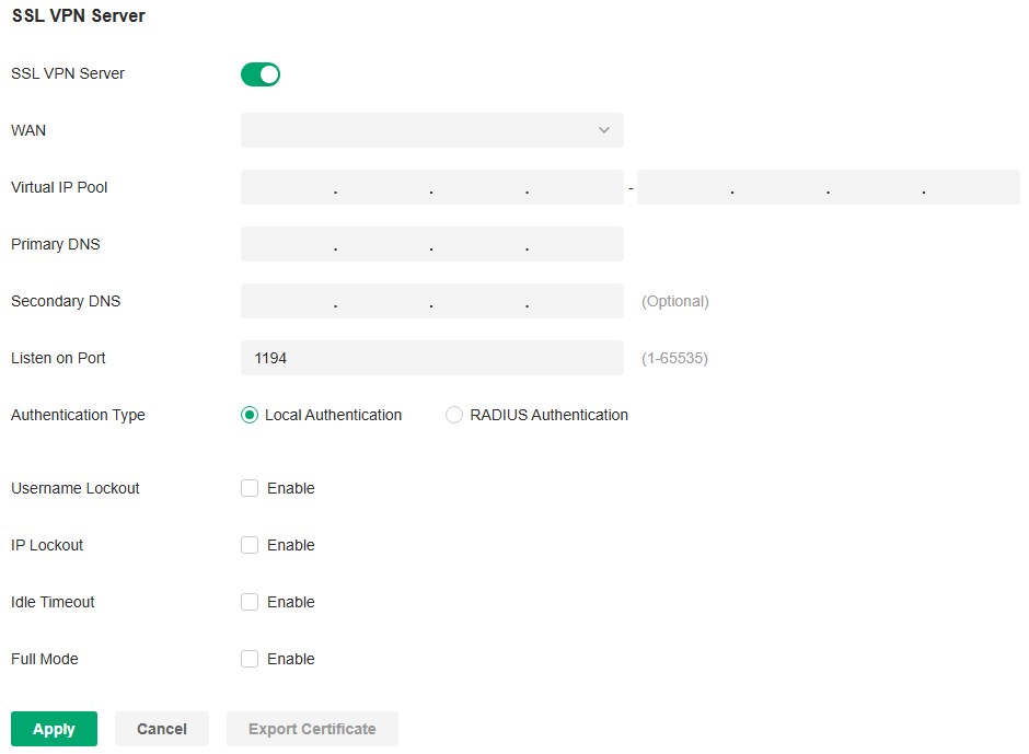
3. Configure the parameters according to your needs. Click Apply.
|
WAN |
Select the port for the SSL VPN server to listen on, and the VPN tunnel will take effect on the port. |
|---|---|
|
Virtual IP Pool |
Set a virtual IP Pool, and the SSL VPN server will assign an IP address to a connected client within the pool. |
|
Primary/Secondary DNS |
Specify the IP address of the DNS server. The clients will be informed of the DNS server, and it can help the clients resolve the domain name. |
|
Listen on Port |
Specify the port for the SSL VPN server to listen on. By default, it is 1194. |
|
Authentication Type |
Select the authentication for the clients: Local Authentication or RADIUS Authentication. If you selected RADIUS Authentication, configure the following parameters: User Group: Specify the default user group in radius authentication mode. When the VPN server cannot find the value of the CLASS attribute in the authentication success message, it will assign the default resource permissions according to the user group. RADIUS Server: Select a RADIUS server profile. Authentication Type: Select the authentication protocol for the RADIUS server. Max Requests: Specify the maximum number of requests sent when no response is received. Request Timeout: Specify the maximum interval for request timeout. After timeout, the request will be sent again. NAS IP: Specify the IP address for the router to communicate with the RADIUS server. |
|
Username Lockout |
When enabled, you can lock out a username in case of excessive login attempts. Max Login Attempts: Specify the maximum failed login attempts for a username. If the number of attempts reaches this amount, the username will be locked out. Lockout Duration: Specify how long the username will be locked out. |
|
IP Lockout |
When enabled, you can lock out an IP address in case of excessive login attempts. Max Login Attempts: Specify the maximum failed login attempts for a login IP. If the number of attempts reaches this amount, the login IP will be locked out. Lockout Duration: Specify how long the login IP will be locked out. |
|
Idle Timeout |
When enabled, the VPN tunnel will close automatically if there is no traffic for the specified amount of time. |
|
Full Mode |
When enable, all traffic will go through the SSL VPN tunnel. When disabled, only the resource-related traffic will go through the tunnel. |
4.Click Export Certificate, enter the WAN IP/Domain Name to access the VPN, then click Export. The VPN configuration file will be exported for clients to access the VPN.
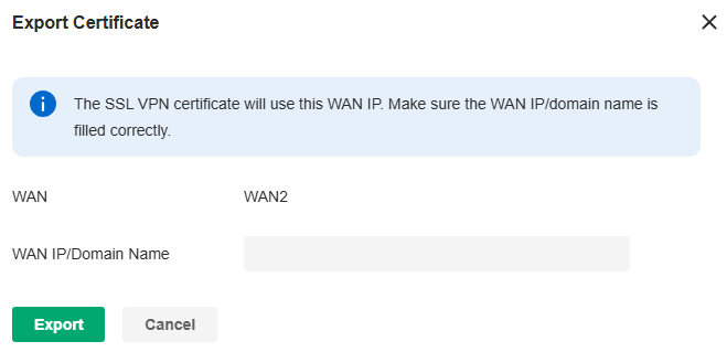
■ Resource Management
In Tunnel Resources, you can configure the resources the clients can access through the VPN tunnel, including IP range and domain name.
In Resource Group, you can add the multiple tunnel resources to a group for better management. By default, two resource groups are provided: Group_ALL (indicates all resources) and Group_LAN (indicates all LAN resources).
1. Launch the controller and access a site.
2. Go to Network Config > VPN > SSL VPN > Resource Management.
3. Click Create New Tunnel Resource to load the following page. Configure the parameters and click Confirm.
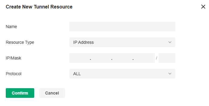
|
Name |
Specify a name for the entry. |
|---|---|
|
Resource Type |
Select the type for the resources: IP Address or Domain Name. If you selected IP Address, configure the following parameters: IP/Mask: Specify IP range the clients can access. Protocol: Select the protocol type that the client can access in the IP range, and the router will filter illegal packets through firewall rules. By default, the value is ALL, and it means there is no restriction on the client. If you selected Domain Name, specify domain name the clients can access. |
4. Click Create New Resource Group to load the following page. Configure the parameters and click Confirm.
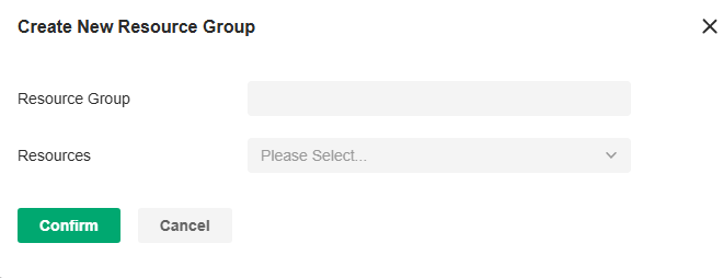
|
Resource Group |
Specify a name for the resource group. |
|---|---|
|
Resources |
Select the resources for the group. |
■ User Group
In User Group, you can add multiple users to a group for better management.
1. Launch the controller and access a site.
2. Go to Network Config > VPN > SSL VPN > User Group.
3. Click Create New User Group to load the following page. Configure the parameters and click Confirm.
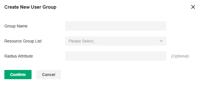
|
Group Name |
Specify a name for the user group. |
|
Resource Group List |
Select the resource group for the user group. |
|
Radius Attribute |
Only valid in radius authentication mode. It maps the user group with radius grouping information (which is carried by the CLASS attribute 25). |
■ User List
In User List, you can view and configure all user settings of the SSL VPN.
1. Launch the controller and access a site.
2. Go to Network Config > VPN > SSL VPN > User List.
3. Click Create New User to load the following page. Configure the parameters and click Confirm.
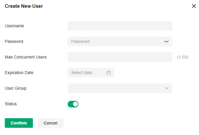
|
Username |
Specify the username a client used for login. |
|---|---|
|
Password |
Specify the password a client used for login. |
|
Max Concurrent Users |
Specify the maximum number of clients using the username for login concurrently. If the number reaches this amount, new login attempts will be rejected. |
|
Expiration Date |
Specify when the user account will expire. |
|
User Group |
Select which group the user belongs to. A user can only be added to one user group. |
|
Status |
Click the checkbox to enable this entry. |
■ Locked Out User
In Locked Out User, you can view the currently locked out users, and add, delete or edit an entry.
1. Launch the controller and access a site.
2. Go to Network Config > VPN > SSL VPN > Locked Out User.
3. Click Add Locked Out User to load the following page. Configure the parameters and click Confirm.
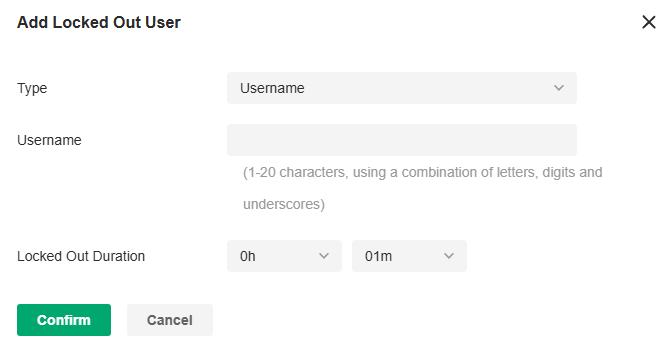
|
Type |
Specify the locked out type. If you selected Username, specify the username of a locked out user. If you selected IP Address, specify the IP address of a locked out user. |
|---|---|
|
Lockout Duration |
Specify how long the entry will be locked out. |
Configure the WireGuard VPN
Overview
WireGuard VPN is a secure, fast and modern VPN protocol. It is based on the UDP protocol and uses modern encryption algorithms to improve work efficiency.
Configuration
■ WireGuard
1. Launch the controller and access a site.
2. Go to Network Config > VPN > WireGuard.
3. Click Create New WireGuard. Configure the parameters and click Apply.

|
Name |
Specify the name that identifies the WireGuard interface. |
|---|---|
|
Status |
Specify whether to enable the WireGuard interface. |
|
MTU |
Specify the MTU value of the WireGuard interface. The default value 1420 is recommended. |
|
Listen Port |
Specify the port number that the WireGuard interface listens to. |
|
Local IP Address |
Specify the IP address of the WireGuard interface. |
|
Private Key |
Specify the private key of the WireGuard interface. The value will be automatically generated on the device, and you can also modify it manually. |
■ Peers
1. Launch the controller and access a site. Go to Network Config > VPN > WireGuard > Peers.
2. Click Create New Peer. Configure the parameters and click Apply.
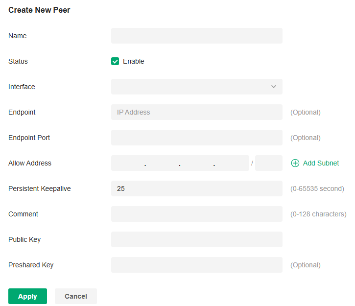
|
Name |
Specify the name that identifies the peer. |
|---|---|
|
Status |
Specify whether to enable the peer. |
|
Interface |
Specify the WireGuard interface to which the peer belongs. |
|
Endpoint |
Specify the IP address of the peer. This parameters is required when the Router actively connects to other WireGurad Server. |
|
Endpoint Port |
Specify the port number of the peer. This parameters is required when the Router actively connects to other WireGurad Server. |
|
Allowed Address |
Specify the address segment that allows traffic to pass through. Generally, it is the same as the WireGuard VPN interface IP configured on the remote device. |
|
Persistent Keepalive |
Specify the tunnel keepalive packet interval. |
|
Comment |
Enter the description of the peer. |
|
Public Key |
Fill in the public key information exported from the remote device. |
|
Preshared Key |
Specify an optional shared key. |
Configuring Network Transmission Settings
Configure Routing Settings
Overview
■ Static Route
Network traffic is oriented to a specific destination, and Static Route designates the next hop or interface where to forward the traffic.
■ Policy Routing
Policy Routing designates which WAN port the router uses to forward the traffic based on the source, the destination, and the protocol of the traffic.
Configuration
■ Static Route
1. Launch the controller and access a site.
2. Go to Network Config > Transmission > Routing > Static Route.
3. Click Create New Route to load the following page and configure the parameters.
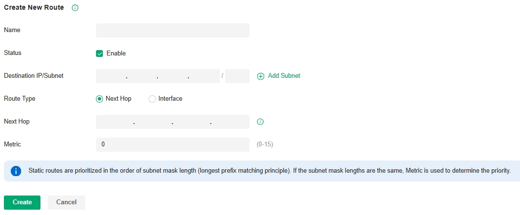
| Name | Enter the name to identify the Static Route entry. |
|---|---|
| Status | Enable or disable the Static Route entry. |
| Destination IP/Subnet | Destination IP/Subnet identifies the network traffic which the Static Route entry controls. Specify the destination of the network traffic in the format of 192.168.0.1/24. You can click Add Subnet to specify multiple Destination IP/Subnets and click the Delete icon to delete them. |
| Route Type | Next Hop: With Next Hop selected, your devices forward the corresponding network traffic to a specific IP address. You need to specify the IP address as Next Hop. Interface: With Interface selected, your devices forward the corresponding network traffic through a specific interface. You need to specify the Interface according to your needs. |
| Metric | Define the priority of the Static Route entry. A smaller value means a higher priority. If multiple entries match the Destination IP/Subnet of the traffic, the entry of higher priority takes precedence. In general, you can simply keep the default value. |
4. Click Create. The new Static Route entry is added to the table. You can click the Edit icon to edit the entry. You can click the Delete icon to delete the entry.
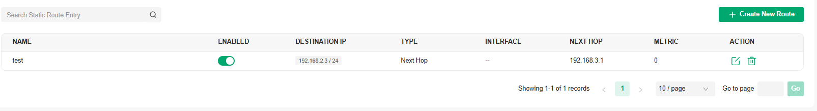
■ Policy Routing
1. Launch the controller and access a site.
2. Go to Network Config > Transmission > Routing > Policy Routing.
3. Click Create New Routing to load the following page and configure the parameters.
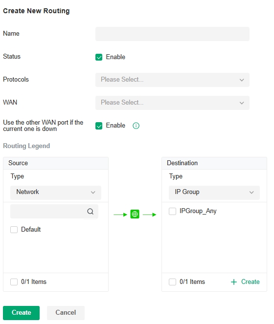
| Name | Enter the name to identify the Policy Routing entry. |
|---|---|
| Status | Enable or disable the Policy Routing entry. |
| Protocols | Select the protocols of the traffic which the Policy Routing entry controls. The Policy Routing entry takes effect only when the traffic matches the criteria of the entry including the protocols. |
| WAN | Select the WAN port to forward the traffic through. If you want to forward the traffic through the other WAN port when the current WAN is down, enable Use the other WAN port if the current WAN is down. |
| Routing Legend | The Policy Routing entry takes effect only when the traffic using specified protocols matches the source and destination which are specified in the Routing Legend. Select the type of the traffic source and destination. Network: Select the network interfaces for the traffic source or destination. IP Group: Select the IP Group for the traffic source or destination. You can click + Create to create a new IP Group. IP-Port Group: Select the IP-Port Group for the traffic source or destination. You can click + Create to create a new IP-Port Group. Location Group: Select the Location Group for the traffic destination. You can click + Create to create a new Location Group. Domain Group: Select the Domain Group for the traffic destination. You can click + Create to create a new Domain Group. |
4. Click Create. The new Policy Routing entry is added to the table. You can click the Edit icon to edit the entry. You can click the Delete to delete the entry.

Configure NAT Settings
Overview
■ Port Forwarding
You can configure Port Forwarding to allow internet users to access local hosts or use network services which are deployed in the LAN.
Port Forwarding helps establish network connections between a host on the internet and the other in the LAN by letting the traffic pass through the specific port of the gateway. Without Port Forwarding, hosts in the LAN are typically inaccessible from the internet for the sake of security.
■ ALG
ALG ensures that certain application-level protocols function appropriately through your gateway.
■ One-to-One NAT
One-to-One NAT will establish a correspondence between a private IP and a public IP, allowing access to the device with the private IP through the corresponding public IP.
■ Disable NAT
Disable NAT allows internal devices to obtain public IP addresses.
Configuration
1. Launch the controller and access a site.
2. Go to Network Config > Transmission > NAT > Port Forwarding.
3. Click Create New Rule to load the following page and configure the parameters.
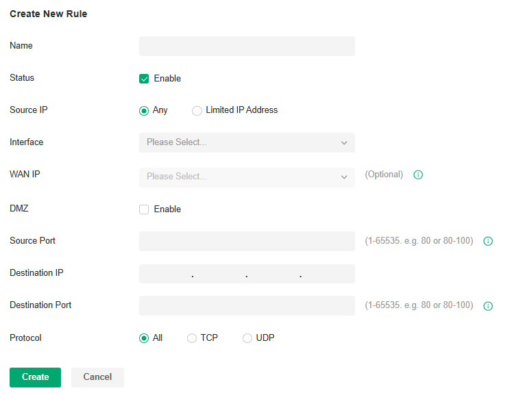
| Name | Enter the name to identify the Port Forwarding rule. |
|---|---|
| Status | Enable or disable the Port Forwarding rule. |
| Source IP | Any: The rule applies to traffic from any source IP address. Limited IP Address: The rule only applies to traffic from specific IP addresses. With this option selected, specify the IP addresses and subnets according to your needs. |
| Interface | Select the interface which the rule applies to. Traffic which is received through the interface is forwarded according to the rule. |
| DMZ |
With DMZ enabled, all the traffic is forwarded to the Destination IP in the LAN, port to port. You need to specify the Destination IP. With DMZ disabled, only the traffic which matches the Source Port and the Protocol is forwarded. The traffic is forwarded to the Destination Port of the Destination IP in the LAN. You need to specify the Source Port, Destination IP, Destination Port, and Protocol. |
| Source Port | The gateway uses the Source Port to receive the traffic from the internet. Only the traffic which matches the Source Port and the Protocol is forwarded. |
| Destination IP | The traffic is forwarded to the host of the Destination IP in the LAN. |
| Destination Port | The traffic is forwarded to the Destination Port of the host in the LAN. |
| Protocol | Network traffic is transmitted using either TCP or UDP protocol. Only the traffic which matches the Source Port and the Protocol is forwarded. If you want both TCP traffic and UDP traffic to be forwarded, select All. |
4. Click Create. The new Port Forwarding entry is added to the table. You can click the Edit icon to edit the entry. You can click the Delete icon to delete the entry.
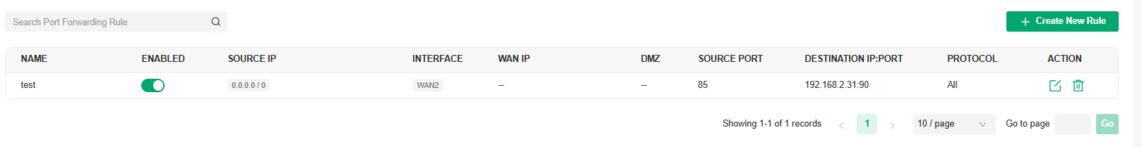
■ ALG
1. Launch the controller and access a site.
2. Go to Network Config > Transmission > NAT > ALG.
3. Enable or disable certain types of ALG according to your needs and click Apply.
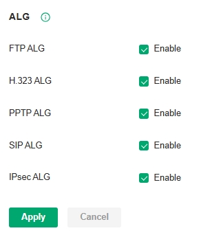
| FTP ALG | FTP ALG allows the FTP server and client to transfer data using the FTP protocol in one of the following scenarios: ● The FTP server is in the LAN, while the FTP client is on the internet. ● The FTP server is on the internet, while the FTP client is in the LAN. ● The FTP server and FTP client are in different LANs. |
|---|---|
| H.323 ALG | H.323 ALG allows the IP phones and multimedia devices to set up connections using the H.323 protocol in one of the following scenarios: ● One of the endpoints is in the LAN, while the other is on the internet. ● The endpoints are in different LANs. |
| PPTP ALG | PPTP ALG allows the PPTP server and client to set up a PPTP VPN in one of the following scenarios: ● The PPTP server is in the LAN, while the PPTP client is on the internet. ● The PPTP server is on the internet, while the PPTP client is in the LAN. ● The PPTP server and PPTP client are in different LANs. |
| SIP ALG | SIP ALG allows the IP phones and multimedia devices to set up connections using the SIP protocol in one of the following scenarios: ● One of the endpoints is in the LAN, while the other is on the internet. ● The endpoints are in different LANs. |
| IPsec ALG | IPsec ALG allows the IPsec endpoints to set up an IPsec VPN in one of the following scenarios: ● One of the endpoints is in the LAN, while the other is on the internet. ● The endpoints are in different LANs. |
■ One-to-One NAT
1. Launch the controller and access a site.
2. Go to Network Config > Transmission > NAT > One-to-One NAT.
3. Click Create New Rule to load the following page and configure the parameters.
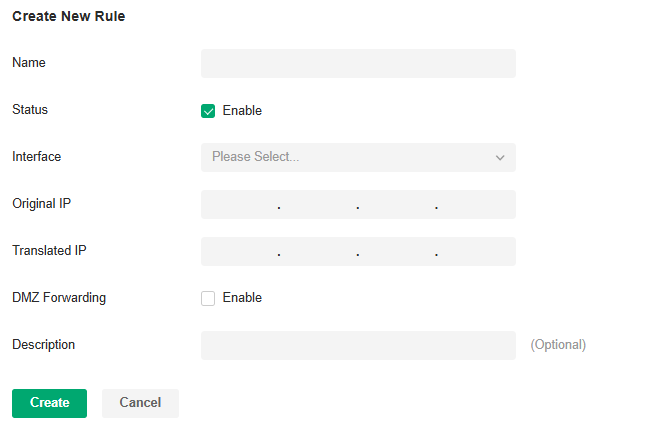
| Name | Enter the name to identify the one-to-one NAT rule. |
|---|---|
| Status | Enable or disable the one-to-one NAT rule. |
| Interface | Specify the effective interface for the rule only when the connection type is Static IP. |
| Original IP | Specify the original IP address for the rule, which means the device’s private IP. The original IP address cannot be the broadcast address, network segment or interface IP. With One-to-One NAT enabled, the original IP will map to the translated IP. |
| Translated IP | Specify the translated IP address for the rule, which means the public IP of device. The translated IP address cannot be the broadcast address, network segment or interface IP. With One-to-One NAT enabled, the original IP will map to the translated IP. |
| DMZ Forwarding | Choose to enable DMZ Forwarding. The packets transmitted to the translated IP address will be forwarded to the host with the original IP address if DMZ Forwarding is enabled. |
| Description | (Optional) Enter a description for identification. |
4. Click Create to add the one-to-one NAT rule
■ Disable NAT
1. Launch the controller and access a site.
2. Go to Network Config > Transmission > NAT > Disable NAT.
3. Click Create New Rule to load the following page and configure the parameters.
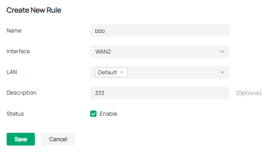
| Name | Enter a name to identify the rule. |
|---|---|
| Interface | Specify the effective interface for the rule. |
| LAN | Specify the effective LAN network for the rule. |
| Description | (Optional) Enter a description for identification. |
| Status | Enable or disable the rule. |
4. Click Create to add the Disable NAT rule.
Configure DHCP Reservation
Overview
It is convenient for networks to use Dynamic IP addresses assigned by Dynamic Host Configuration Protocol (DHCP), however, for devices that need to be reliably accessed, it is ideal to set fixed IP addresses for them. DHCP Reservation allows you to reserve specific IP addresses for devices in your network, and centrally manage the IP addresses.
Configuration
■ To manually add DHCP Reservation entries:
1. Launch the controller and access a site.
2. Go to Network Config > Transmission > DHCP Reservation.
3. Click Create New DHCP Reservation Entry and configure the parameters. Then click Apply.
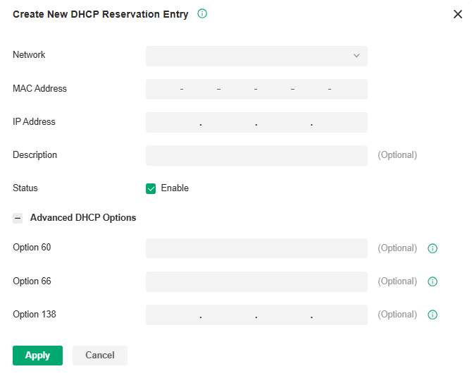
| Network | Select the network the DHCP reservation entry is used for. |
|---|---|
| MAC Address | Specify the MAC address of the device for which you want to reserve an IP address. |
| IP Address | Specify the fixed IP address for the device. |
| Description | Enter description for the entry for identification. |
| Status | Enable or disable the entry. |
| Advanced DHCP Options | Configure the advanced DHCP options if needed. Option 60: Enter the value for DHCP Option 60. DHCP clients use this field to optionally identify the vendor type and configuration of a DHCP client. Mostly it is used in the scenario where the APs apply for different IP addresses from different servers according to the needs. Option 66: Enter the value for DHCP Option 66. It specifies the TFTP server information and supports a single TFTP server IP address. Option 138: Enter the value for DHCP Option 138. It is used in discovering the devices by the system. |
■ To import DHCP Reservation entries in batch:
1. Launch the controller and access a site.
2. Go to Network Config > Transmission > DHCP Reservation.
3. Click Export to export the template in csv format. Based on this template, you can add custom address reservation entries that need to be imported.
4. Click Import and import the customized template. You can download the template, then edit and upload it for batch import.
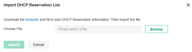
Configure Bandwidth Control
Overview
Bandwidth Control optimizes network performance by limiting the bandwidth of specific sources.
Configuration
1. Launch the controller and access a site.
2. Go to Network Config > Transmission > Bandwidth Control.
3. In Bandwidth Control, enable Bandwidth Control globally and configure the parameters. Then click Apply.
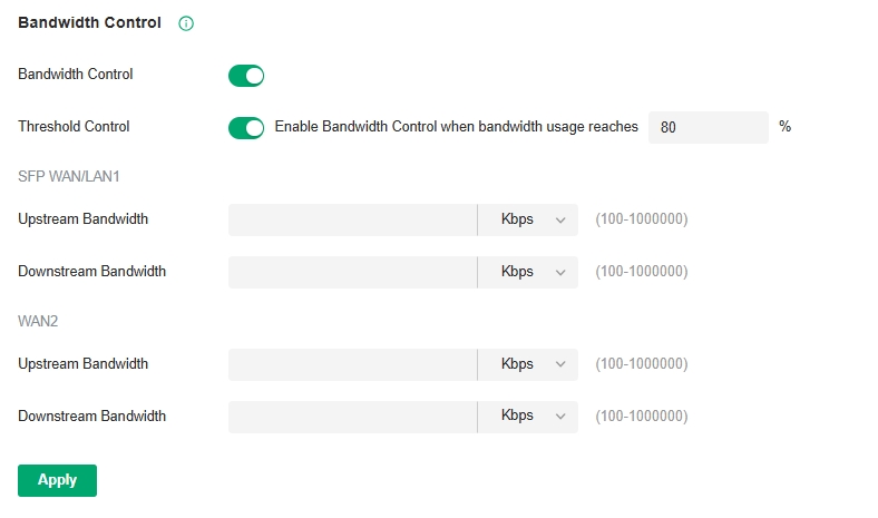
| Threshold Control | With Threshold Control enabled, Bandwidth Control takes effect only when total bandwidth usage reaches the specified percentage. You need to specify the total Upstream Bandwidth and Downstream Bandwidth of the WAN ports. It’s recommended to use the Test Speed tool to decide the actual Upstream Bandwidth and Downstream Bandwidth. |
|---|
4. In Bandwidth Control Rule List, click Create New Rule to load the following page and configure the parameters.
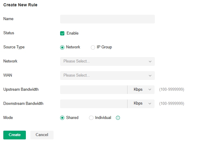
| Name | Enter the name to identify the Bandwidth Control rule. |
|---|---|
| Status | Enable or disable the Bandwidth Control rule. |
| Source Type | Network: Limit the maximum bandwidth of specific LAN networks. With this option selected, select the networks, which you can customize in Wired Networks > LAN Networks. For detailed configuration, refer to the wired network configuration chapter in this guide. IP Group: Limit the maximum bandwidth of specific IP Groups. With this option selected, select the IP Groups, which you can customize in Profiles > Groups. For detailed configuration of IP groups, refer to the network profile configuration section in this guide. |
| WAN | Select the WAN port which the rule applies to. |
| Upstream Bandwidth | Specify the limit of Upstream Bandwidth, which the specific local hosts use to transmit traffic to the internet through the gateway. |
| Downstream Bandwidth | Specify the limit of Downstream Bandwidth, which the specific local hosts use to receive traffic from the internet through the gateway. |
| Mode | Specify the bandwidth control mode for the specific local hosts. Shared: The total bandwidth for all the local hosts is equal to the specified values. Individual: The bandwidth for each local host is equal to the specified values. |
5. Click Create. The new Bandwidth Control rule is added to the list. You can click the Edit icon to edit the rule. You can click the Delete icon to delete the rule.

Configure Session Limit
Overview
Session Limit optimizes network performance by limiting the maximum sessions of specific sources.
Configuration
1. Launch the controller and access a site.
2. Go to Network Config > Transmission > Session Limit.
3. In Session Limit, enable Session Limit globally and click Apply.

4. In Session Limit Rule List, click Create New Rule to load the following page and configure the parameters.
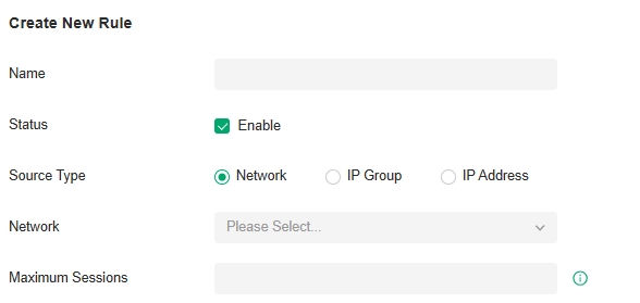
| Name | Enter the name to identify the Session Limit rule. |
|---|---|
| Status | Enable or disable the Session Limit rule. |
| Source Type | Network: Limit the maximum sessions of specific LAN networks. With this option selected, select the networks, which you can customize in Wired Networks > LAN Networks. For detailed configuration, refer to the wired network configuration chapter in this guide. IP Group: Limit the maximum sessions of specific IP Groups. With this option selected, select the IP Groups, which you can customize in Profiles > Groups. For detailed configuration of IP groups, refer to the network profile configuration section in this guide. |
| Maximum Sessions | Enter the maximum sessions of the specific sources. |
5. Click Save. The new Session Limit rule is added to the list. You can click the Edit icon to edit the rule. You can click the Delete icon to delete the rule.
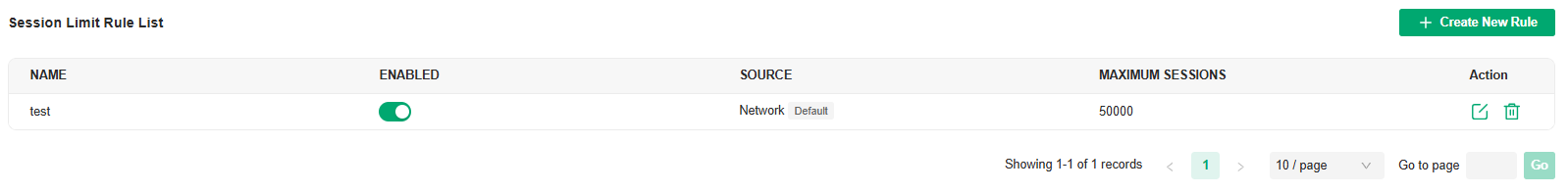
Configure Gateway QoS
■ Gateway QoS Service
In Gateway QoS Service, you can define service entries that will appear as matching conditions for you to choose when configuring the rules of related modules like QoS. The default entries cannot be edited or deleted. You can add other entries if your service is not in the list.
1. Launch the controller and access a site.
2. Go to Network Config > Transmission > Gateway QoS.
3. Click Create New Gateway QoS Service.
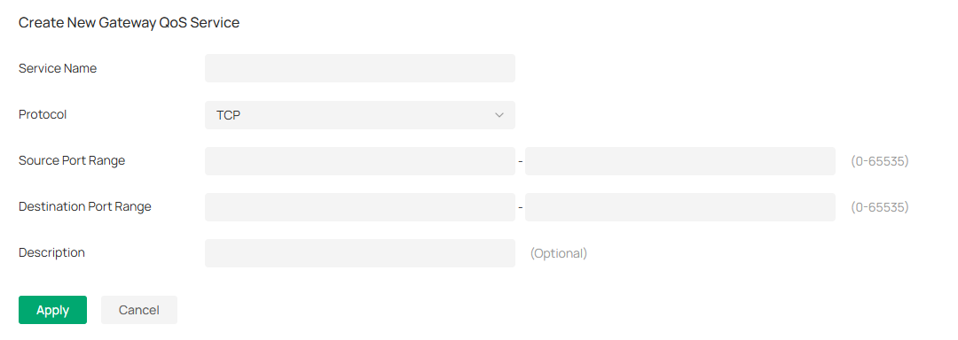
| Service Name | Enter a name for the service. Only letters, digits or underscores are allowed. |
|---|---|
| Protocol | Specify the protocol for the service. The system predefined protocols include TCP, UDP, TCP/UDP and ICMP. For other protocols, select the option Other. |
| Source Port Range | Specify the source port range for the service. Packets whose source port and destination port are both in the range are considered as the target packets. |
| Destination Port Range | Specify the destination port range for the service. Packets whose source port and destination port are both in the range are considered as the target packets. |
| Description | Enter a brief description for the service to facilitate your management. |
■ Gateway QoS Service
This page allows you to configure rules to limit various data flows. In this way, you can optimize the network performance by reasonably utilizing the bandwidth.
1. Launch the controller and access a site.
2. Go to Network Config > Transmission > Gateway QoS > Bandwidth Control.
3. Click Create New Rule.
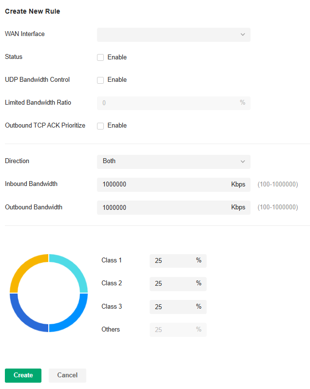
4. Configure the parameters and click Apply.
| WAN Interface | Select the WAN port. You can configure the QoS rule for a WAN port only when the port is enabled. |
|---|---|
| Status | Enable or disable QoS for the current entry. |
| UDP Bandwidth Control | Check the box to enable UDP bandwidth control. |
| Limited Bandwidth Ratio | When UDP Bandwidth Control is enabled, specify the bandwidth ratio of UDP at each level of class1/2/3/other. |
| Outbound TCP ACK Prioritize | Check the box to prioritize outbound TCP ACK packets. This function ensures that traffic is not slowed down by remote hosts waiting for ACK packets before sending further traffic. |
| Direction | Specify the direction of the controlled traffic. “out” means control sending packets. “in” means receiving packets. “both” means both are controlled. |
| Inbound/Outbound Bandwidth | Enter the maximum threshold of the inbound/outbound bandwidth. |
| Class1/Class2/Class3/Others | Specify the proportion of the maximum bandwidth that Class1, Class2, Class3 and Others can occupy to limit the bandwidth usage of specific classification traffic. |
■ Class Rule
This page allows you to add or delete class rules. Rules will be matched from top to bottom according to the rule sequence number. When the traffic matches a rule, it will be assigned to the corresponding class and will not continue to match down.
1. Launch the controller and access a site.
2. Go to Network Config > Transmission > Gateway QoS > Class Rule.
3. Click Create New Class Rule.
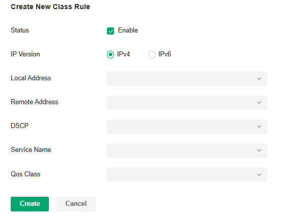
4. Configure the parameters and click Apply.
| Status | Check the box to enable the rule. |
|---|---|
| IP Version | Specify the protocol version: IPv4 or IPv6. |
| Local Address | Match the source IP address of the traffic. For IPv4 protocol, you can use the IP Group object configured in the Profiles > Groups module. For the IPv6 protocol, you can use the IPv6 Group object configured in the Profiles > Groups module. |
| Remote Address | Match the destination IP address of the traffic. For IPv4 protocol, you can use the IP Group object configured in the Profiles > Groups module. For the IPv6 protocol, you can use the IPv6 Group object configured in the Profiles > Groups module. |
| DSCP | Match the DSCP value of the traffic: BE, CS, AF, or EF. |
| Service Name | Match the port number of the traffic. Select the service type object defined in the Preference > Service Type module. |
| QoS Class | Select the category of traffic that meets the rule. |
■ VoIP Prioritization
This page allows you to configure VoIP prioritization.
1. Launch the controller and access a site.
2. Go to Network Config > Transmission > Gateway QoS > VoIP Prioritization.
3. Enable the first priority for VoIP SIP/RTP and enter the SIP UDP port. Then apply the settings.
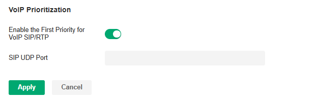
| Enable the First Priority for VoIP SIP/RTP | Check the box to enable prioritize VoIP traffic. |
|---|---|
| SIP UDP Port | Enter the UDP port ID of the VoIP traffic. |
■ Tag Outbound Traffic
This page allows you to add a DSCP or Precedence value for traffic in different classes.
1. Launch the controller and access a site.
2. Go to Network Config > Transmission > Gateway QoS > Tag Outbound Traffic.
3. Check the box for your desired class and select the DSCP or Precedence value.
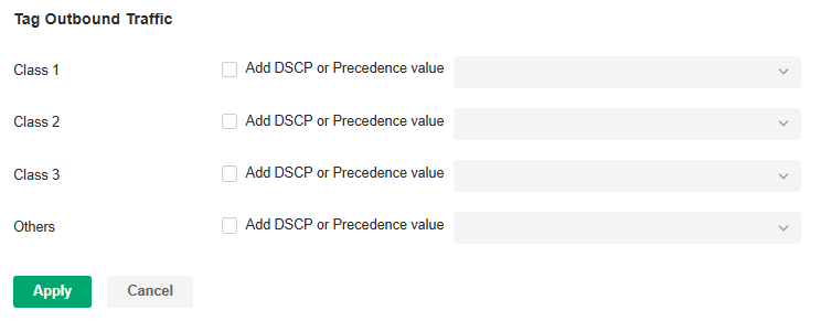
| Class 1/2/3/Others | Check the box and select the DSCP or Precedence value for traffic. |
|---|
Configure Switch QoS
■ DSCP 802.1p Mapping
The DSCP 802.1p Mapping function is used to match the DSCP priority in different packets, then map them to the 802.1p priority. This rule has a lower priority than the VLAN Priority Mapping rule.
1. Launch the controller and access a site.
2. Go to Network Config > Transmission > Switch QoS.
3. In DSCP 802.1p Mapping, the system provides a default rule. You can also click Create New Rule to add a new rule.

4. Set different 802.1p mapping rules for different DSCP packets.
| Name | Enter a name to identify the rule. |
|---|---|
| DSCP Priority | Displays the DSCP priority. |
| 802.1p Priority | Specify the DSCP-to-802.1p mapping. The ingress packets are first mapped to 802.1p priority based on the DSCP-to-802.1p mappings, then to TC queues according to the 802.1p queue mappings. |
| DSCP Remap | Select the DSCP priority to which the original DSCP priority will be remapped. |
■ 802.1p Queue Mapping
The 802.1p Queue Mapping function is used to classify the packets based on the value of 802.1p priority, then map them to different queues. IEEE 802.1p standard defines three bits in 802.1Q tag as PRI filed. The PRI values are called 802.1p priority and used to represent the priority of the layer 2 packets. This function requires packets with VLAN tags.
1. Launch the controller and access a site.
2. Go to Network Config > Transmission > Switch QoS.
3. In 802.1p Queue Mapping, the system provides a default rule. You can also click Create New Rule to add a new rule.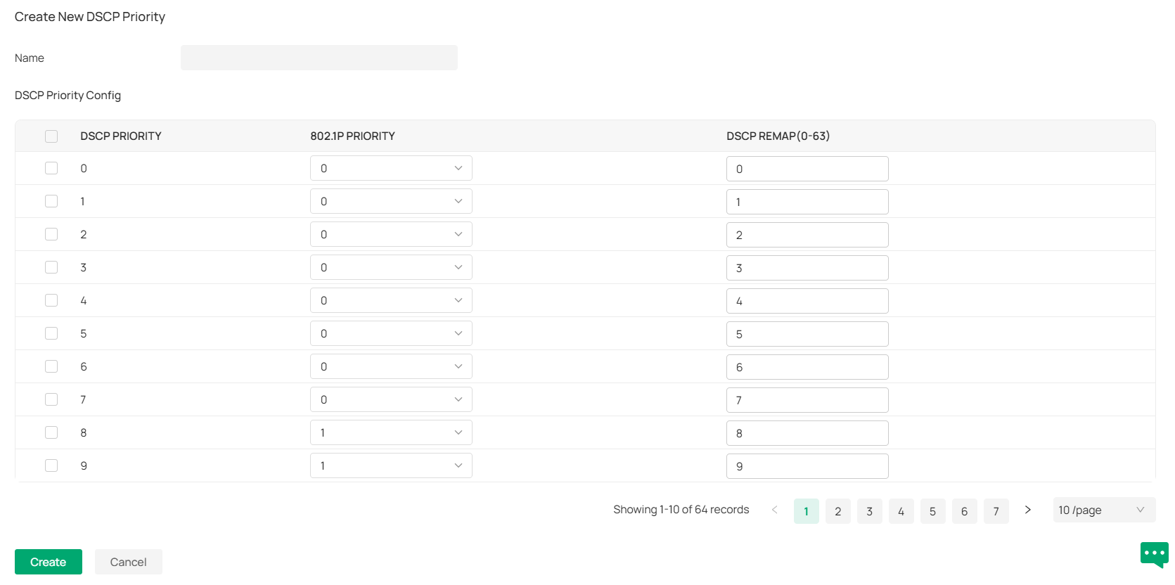
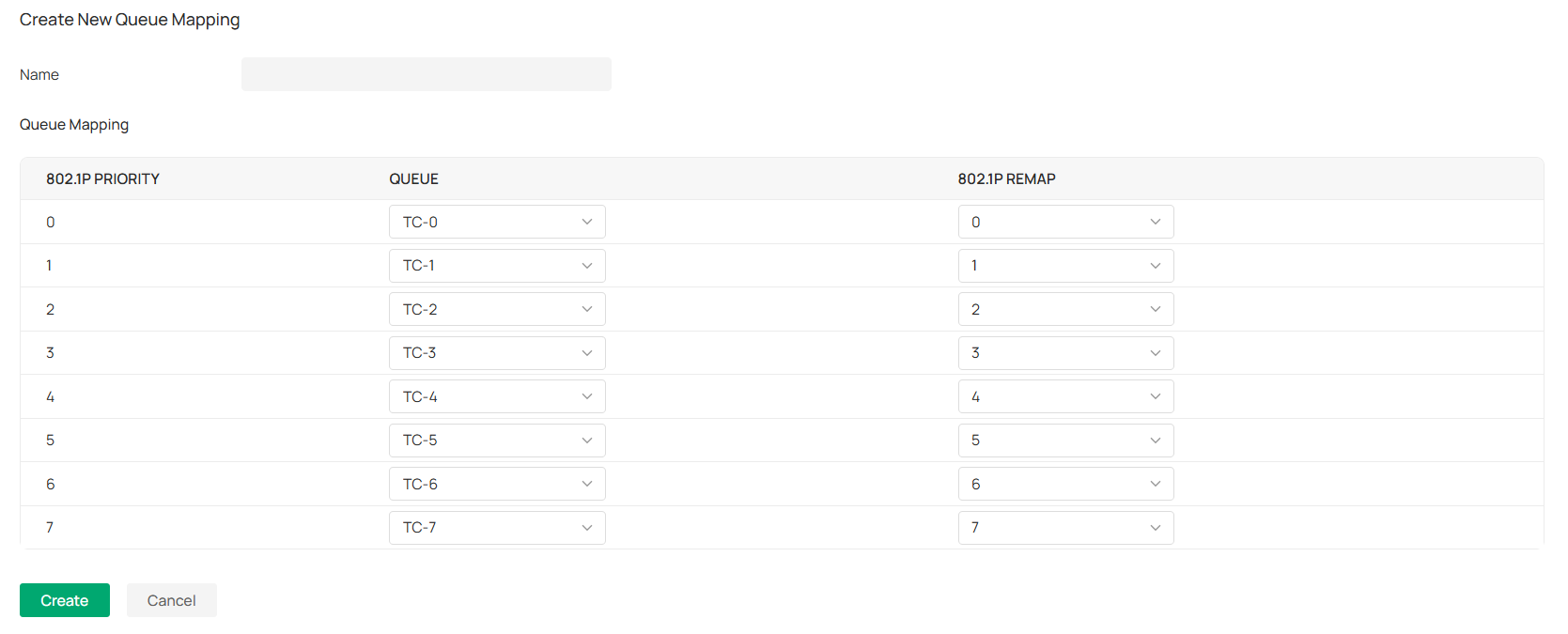
4. Configure the mapping relationship between the 802.1p priority and the queue.
| Name | Enter a name to identify the rule. |
|---|---|
| 802.1p Priority | Displays the number of 802.1p priority. In QoS, 802.1p priority is used to represent class of service. |
| Queue | Select the TC queue for the desired 802.1p priority. |
| 802.1p Remap | 802.1p Remap is used to modify the 802.1p priority of the ingress packets. When the switch detects the 802.1p priority of the packets, it will modify the value of packets 802.1p priority according to the map. Here you can view and configure 802.1p Remap. |
■ Queue Scheduler Profile
The Queue Scheduler Profile function is used to set the scheduler rule for the corresponding 802.1p queue.
1. Launch the controller and access a site.
2. Go to Network Config > Transmission > Switch QoS.
3. In Queue Scheduler Profile, the system provides a default rule. You can also click Create New Rule to add a new rule.
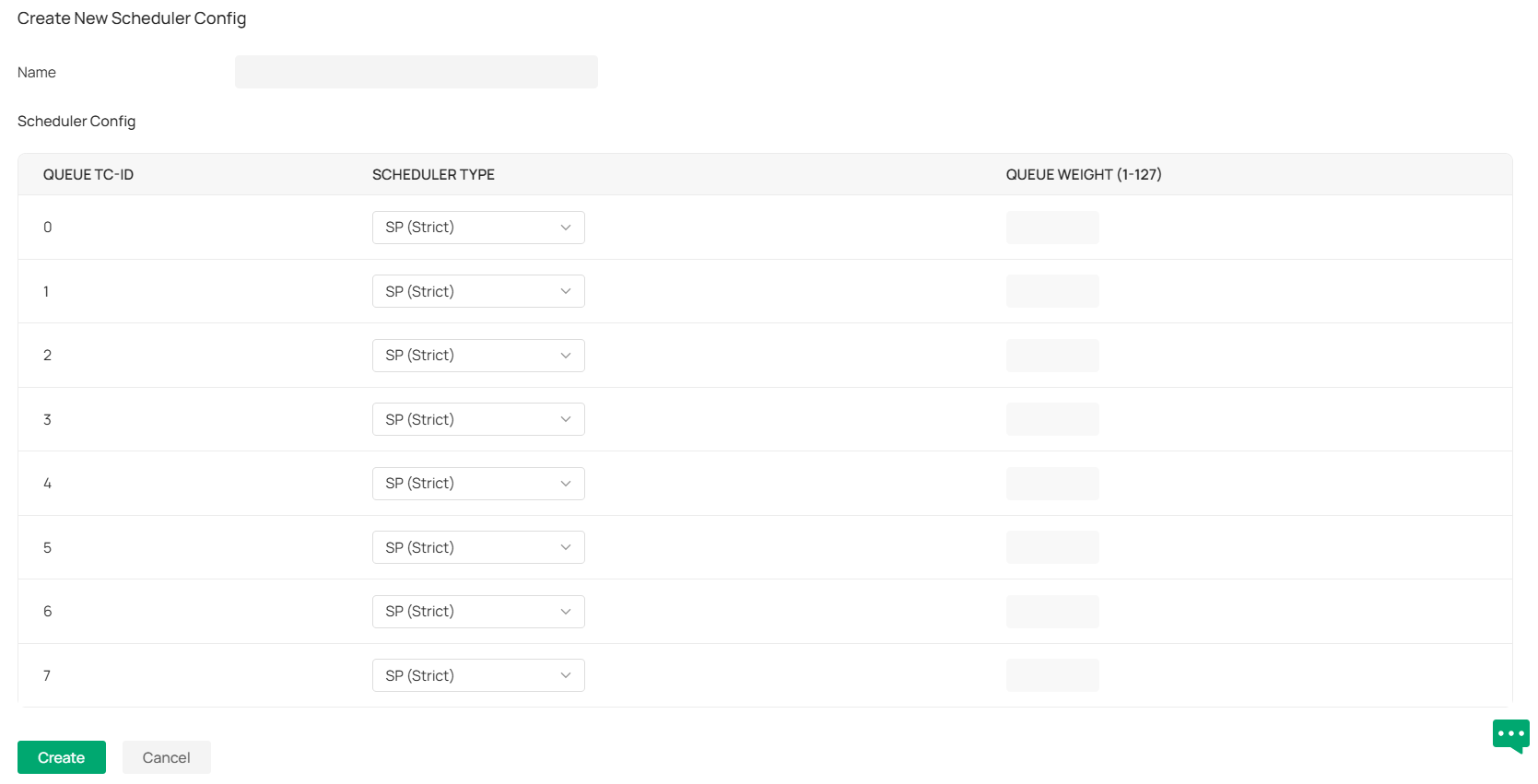
4. Configure scheduling rules for different queues.
| Name | Enter a name to identify the rule. |
|---|---|
| Queue TC-id | Displays the ID number of priority Queue. |
| Scheduler Type | Select the type of scheduling used for the corresponding queue. When the network congestion occurs, the port will determine the forwarding sequence of the packets according to the type. Strict: In this mode, the switch will use SP (Strict Priority) to process the traffic in different queues. When congestion occurs, the traffic will be transmitted according to its queue priority strictly. The queue with higher priority will occupy the whole bandwidth. Packets in the queue with lower priority can be sent only when the queue with higher priority is empty. Weighted: In this mode, the switch will use WRR (Weighted Round Robin) to process the traffic in different queues. When congestion occurs, all the traffic will be transmitted, but the bandwidth that each traffic queue occupies will be allocated based on the queue weight. Note: If the two scheduler types are both applied to a port, the queues in Strict mode will take precedence. |
| Queue Weight | Specify the queue weight for the desired queue. This value can be set only in the Weighted mode. |
Configure OUI Based VLAN
Overview
The OUI Based VLAN function can perform VLAN and priority division and processing on device data packets starting with specific MAC addresses based on OUIs.
Configuration
1. Launch the controller and access a site.
2. Go to Network Config > Transmission > OUI Based VLAN.
3. Click Create New Switch Rule.
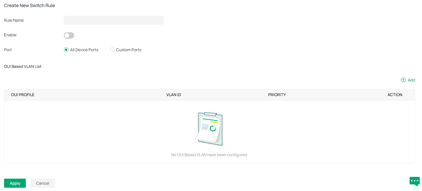
4. Specify the rule name and enable the function.
5. Specify the effective ports. You can choose all device ports or specify some ports of some switches for the rule to take effect.
6. In the OUI Based VLAN List, Click Add to add an OUI Based VLAN.
Note: To ensure normal transmission of data, please add the VLAN ID set as OUI Based VLAN to the Untagged Networks of the LAN Profile to which the rule needs to be applied, and bind the Profile to the corresponding port.
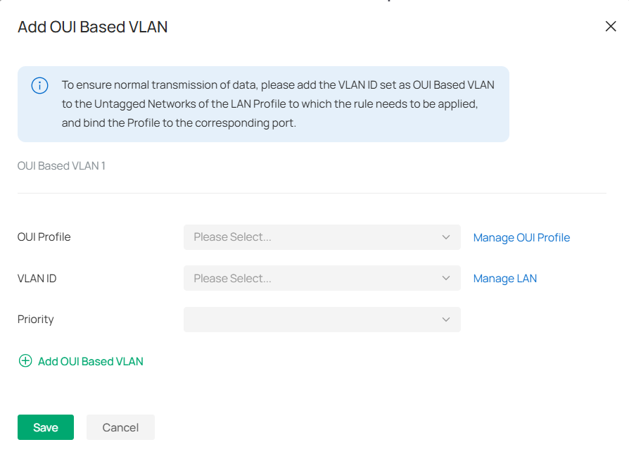
| OUI Profile | Specify the corresponding OUI Profile. |
|---|---|
| VLAN ID | Specify the corresponding OUI Based VLAN ID. |
| Priority | Specify the priority, and the corresponding data packet will be marked with this priority for transmission. |
Configuring Network Profiles
Profiles section is used to configure and record your custom settings for site configurations. After creating the profiles, you can apply them to multiply configurations for different sites, saving you from repeatedly setting up the same information.
Create Groups
Overview
Groups section allows you to customize client groups based on IP, IP-Port, MAC Address, or Domain. You can set different rules for the groups profiles which can be shared and applied to ACL, Routing, NAT, etc. in site configuration.
Configuration
To configure the group profiles, follow these steps:
1. Launch the controller and access a site.
2. Go to Network Config > Profile > Groups.
3. Click Create New Group to add a new group profile.

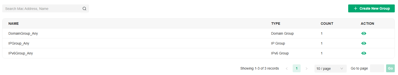
4. Enter a name, select the type, and configure the corresponding parameters for the new group profile.
■ To create an IP group:
Choose the IP Group type and specify IP subnets.
■ To create an IPv6 group:
Choose the IPv6 Group type and specify IPv6 addresses.
■ To Create an IP-Port group:
Choose the IP-Port Group type and specify the IP-Port type and ports, while it is optional to specify IP subnets. If you only specify ports without entering any IP subnets, it means the group contains the specified ports for all IP addresses.
■ To create an IPv6-Port group:
Choose the IPv6-Port Group type and specify the IP-Port type and ports, while it is optional to specify IPv6 addresses. If you only specify ports without entering any IPv6 addresses, it means the group contains the specified ports for all IPv6 addresses.
■ To configure a MAC group:
Choose the MAC Group type and add MAC addresses in the MAC Address List.
■ To configure a location group:
Choose the Location Group type and select locations. You can enter a description for identification.
■ To configure a domain group:
Choose the Domian Group type and specify the domain names. You can specify up to 16 domain names for the group. The domain name can be complete, such as www.baidu.com and www.twitter.com; it can also contain wildcards, such as *.google.com, which will match domain names such as www.google.com, pam.google.com and google.com in special cases.
■ To configure an OUI profile group:
Choose the OUI Profile Group type and add OUIs in the OUI List.
5. Click Apply to save the entry.
You can view and edit the list, and export the MAC group if needed. You can apply the customized profiles during site configuration.

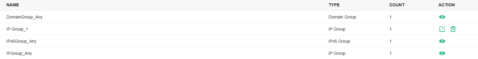
Create Time Range Profiles
Overview
Time Range section allows you to customize time-related configurations. You can set different time range templates which can be shared and applied to wireless schedule, PoE schedule, etc. in site configuration.
Configuration
To configure the time range profiles, follow these steps:
1. Launch the controller and access a site.
2. Go to Network Config > Profile >Time Range.
3. Click Create New Time Range to add a new time range entry. By default, there is no entry in the list.

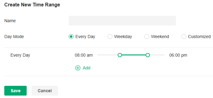
4. Enter a Name for the new entry, select the Day Mode, and specify the time range. Click +Add to add a new time period.
|
Name |
Enter a name for the new entry, and it is a string with 1 to 64 ASCII symbols. |
|---|---|
|
Day Mode |
Select Every Day, Weekday, Weekend, or Customized first before specifying the time range for each day. Every Day: You only need to set the time range once, and it will repeat every day. Weekday: You only need to set the time range once, and it will repeat every weekday from Monday to Friday. Weekend: You only need to set the time range once, and it will repeat every Saturday and Sunday. Customized: You are able to set different time range for the chosen day(s) based on your needs. When a day is not chosen, the WiFi is open all day by default. |
5. Save the entry. Now you can apply them to site configuration. Now you can apply the customized profiles during site configuration.


Create Rate Limit Profiles
Overview
Rate Limit allows you to customize rate-related configurations. You can set different rate limit templates. They can be bound with wireless network to limit the upload/download rate of clients connected the SSID, and applied to specific types of Portal, such as Local User and Voucher. After creating the profiles, you can apply them to multiple configurations, saving you from repeatedly setting up the same information.
Configuration
To configure the rate limit profiles, follow these steps:
1. Launch the controller and access a site.
2. Go to Network Config > Profile > Rate Limit.
3. By default, there is an entry with no limits, and it can not be deleted. You can click Create New Rate Limit Profile to add a new group entry.

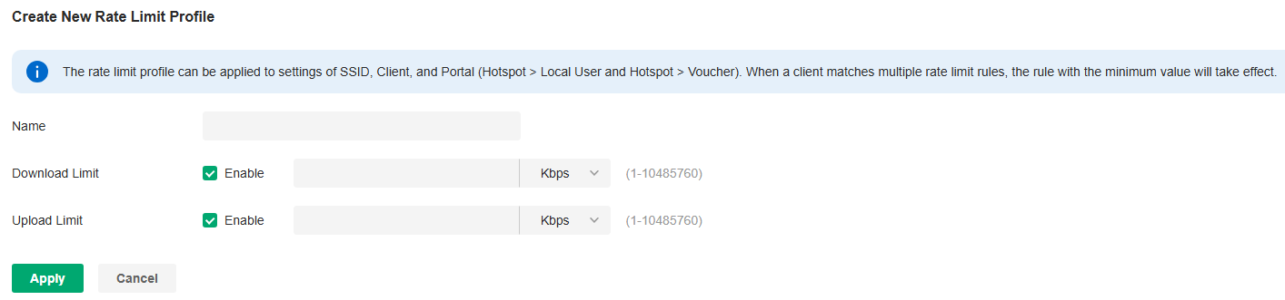
4. Enter a name and specify the download/upload rate limit for the new entry. After saving the newly added entry, you can apply them to other configurations such as Portal and Wireless Settings.
|
Name |
Enter a name to identify the created rate limit profile. |
|---|---|
|
Download Limit |
Enable the download limit, and specify the rate limit correspondingly in Kbps or Mbps. |
|
Upload Limit |
Enable the upload limit, and specify the rate limit correspondingly in Kbps or Mbps. |
5. Click Apply to save the entry. Now you can apply the customized profiles during site configuration.
Create PPSK Profiles
Overview
PPSK is a security solution for you to manage individual client devices without much complexity. With PPSK, each user is assigned with a unique passphrase for authentication. Also, it allows the binding of a passphrase and the device MAC address(es), and thus only the specified device can be authenticated using the passphrase. In PPSK, you can create a PPSK list and apply it to multiple wireless networks, saving you from repeatedly setting up the same information.
Configuration
To configure the PPSK profiles, follow these steps:
1. Launch the controller and access a site.
2. Go to Network Config > Profile > PPSK. Click Create New PPSK Profile to add a new PPSK profile .

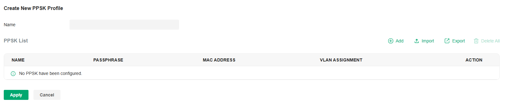
3. Enter a name for the new profile.
4. Add new entries to the PPSK profile.
• Method 1: Add entries manually
Click Add and select Manually for PPSK Generation. Configure the parameters.

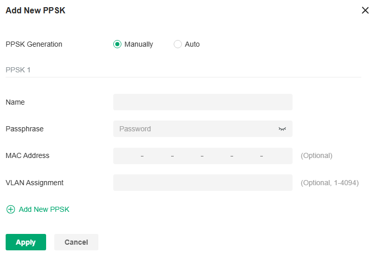
|
Name |
Enter a name to identify the created PPSK. |
|---|---|
|
Passphrase |
Enter a passphrase, and the client will use the passphrase for authentication. |
|
MAC Address |
(Optional) Enter the MAC address of the device that can use the passphrase for authentication. |
|
VLAN Assignment |
(Optional) Enter the VLAN ID, and the client who uses the passphrase for authentication will be assigned to the specified VLAN. |
Apply the settings. The new PPSK entry will be created.
• Method 2:
Click Add and select Auto for PPSK Generation. Configure the parameters and apply the settings.

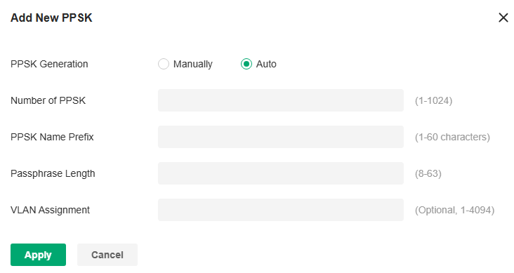
|
Number of PPSK |
Enter the number of PPSK entries to create. |
|---|---|
|
PPSK Name Prefix |
Enter the prefix of the names for the created PPSK entries. |
|
Passphrase Length |
Enter the passphrase length. |
|
VLAN Assignment |
(Optional) Enter the VLAN ID, and the client who uses the passphrase for authentication will be assigned to the specified VLAN. |
Apply the settings. New PPSK entries will be created automatically.
• Method 3: Export and Import entries in batch
After creating PPSK entries, you can click Export to save them to a file locally, then access another site and click Import to import them in batches from the file.

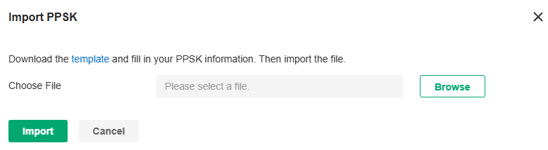
5. Click Apply to save the entry. Now you can apply the customized profiles during site configuration.
Create RADIUS Profile Profiles
Overview
RADIUS (Remote Authentication Dial In User Service) is a client/server protocol that provides for the AAA (Authentication, Authorization, and Accounting) needs of modern IT environments.
In authentication services including 802.1X, Portal and MAC-Based Authentication, Omada devices operate as clients of RADIUS to pass user information to designated RADIUS servers. A RADIUS server maintains a database which stores the identity information of legal users. It authenticates users against the database when the users are requesting to access the network, and provides authorization and accounting services for them.
A RADIUS profile records your custom settings of a RADIUS server. After creating a RADIUS profile, you can apply it to multiple authentication policies like Portal and 802.1X, saving you from repeatedly entering the same information.
Configuration
■ Configure the Built-in RADIUS Profile (for on-premise controllers only)
a. Launch the controller and access a site.
b. Go to Network Config > Profile > RADIUS Profile.
c. An on-premise controller provides a Built-in RADIUS Profile. Click the edit icon of the profile, then add or import RADIUS users.
To add a new RADIUS user, click Add New RADIUS User and configure the parameters.

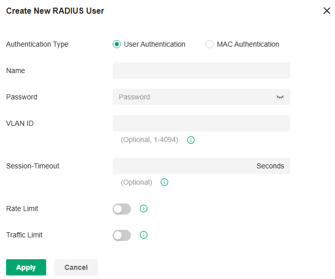
|
Authentication Type |
Select the Authentication Type. User Authentication: Select this option and enter the user Name and Password for authentication. MAC Authentication: Select this option and enter the MAC Address for authentication. |
|---|---|
|
VLAN ID |
Enter a VLAN ID to assign VLANs to users. |
|
Session-Timeout |
Configure the authentication expiration time for users. |
|
Rate Limit |
When enabled, you can set limits for Uplink Rate and Downlink Rate of each client to balance bandwidth usage. This function applies to the portal service only. |
|
Traffic Limit |
When enabled, you can set limits for Uplink Traffic and Downlink Traffic of each client. This function applies to the portal service only. |
To import RADIUS users in batches, click Import, download the template and fill in your Radius User information. Then import the file.

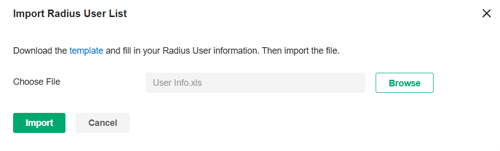
■ Create New RADIUS Profile
a. Launch the controller and access a site.
b. Go to Network Config > Profile > RADIUS Profile.
c. Click Create New RADIUS Profile. Configure the parameters and save the settings.

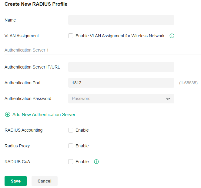
|
Name |
Enter a name to identify the RADIUS profile. |
|---|---|
|
VLAN Assignment |
This feature allows the RADIUS server to place a wireless user into a specific VLAN based on the credentials supplied by the user. To use the feature, you should create the specific VLAN first. And the user-to-VLAN mappings must be already stored in the RADIUS server database. Note: 1. VLAN Assignment is not currently supported when a client is authenticated by Portal with External RADIUS Server or RADIUS Hotspot. 2. VLAN Assignment is applicable only when the device supports the feature. To make this feature work properly, it is recommended to upgrade your devices to the latest firmware version. |
|
Authentication Server IP |
Enter the IP address of the authentication server. |
|
Authentication Port |
Enter the UDP destination port on the authentication server for authentication requests. |
|
Authentication Password |
Enter the password that will be used to validate the communication between network devices and the RADIUS authentication server. |
|
RADIUS Accounting |
Click the checkbox to enable RADIUS Accounting to meet billing needs. This feature is only available for APs with Portal to account for wireless clients. |
|
Interim Update |
Click the checkbox to enable Interim Update. By default, the RADIUS accounting process needs only start and stop messages to the RADIUS accounting server. With Interim Update enabled, network devices will periodically send an Interim Update (a RADIUS Accounting Request packet containing an “interim-update” value) to the RADIUS server. An Interim Update updates the user’s session duration and current data usage. |
|
Interim Update Interval |
Enter an appropriate interval between the updates of users’ session duration and current data usage. |
|
Accounting Server IP |
Enter the IP address of the RADIUS accounting server. |
|
Accounting Port |
Enter the UDP destination port on the RADIUS server for accounting requests. |
|
Accounting Password |
Enter the password that will be used to validate the communication between network devices and the RADIUS accounting server. |
|
Radius Proxy |
With this option enabled, the Controller will act as a proxy to forward the device’s authentication messages to the corresponding RADIUS server. |
|
RADIUS CoA |
If enabled, TP-Link devices will act as a RADIUS Dynamic Authorization Server and will respond to RADIUS Change-of-Authorization and Disconnect messages sent by the RADIUS servers. This option is only supported by EAP PPSK, EAP MAC-Based Authentication, and EAP WPA-Enterprise. |
|
CoA Password |
CoA password is used to authenticate CoA and Disconnect messages sent by the RADIUS servers. The password must be the same as the secret used by RADIUS servers to send the CoA and Disconnect messages. |
Create LDAP Profiles
Overview
The Lightweight Directory Access Protocol (LDAP) is an industry standard protocol for maintaining and accessing directory information over a network. LDAP Authentication allows you to bind the device to an LDAP server and use that server to authenticate LAN clients. Google LDAP profile is designed for use with Google Workspace’s Secure LDAP.
Configure a Common LDAP Profile
1. Launch the controller and access a site.
2. Go to Network Config > Profile > LDAP Profile.
3. Click Create New LDAP Profile to add a new profile .

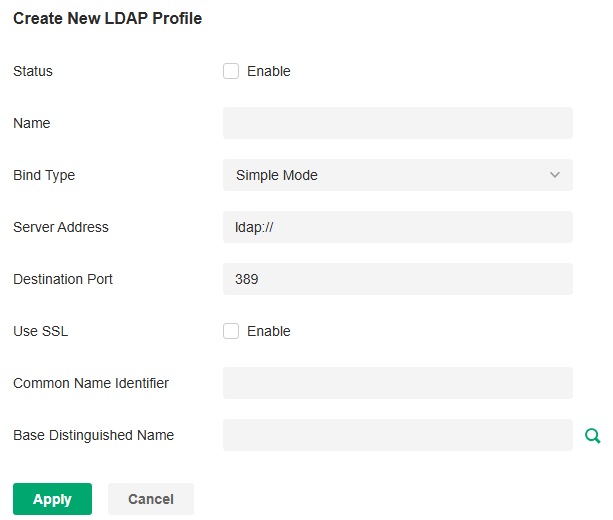
4. Configure the parameters.
|
Status |
Check the box to enable LDAP Authentication. |
|---|---|
|
Name |
Specify the profile name. |
|
Bind Type |
Select the LDAP Authentication mode: Anonymous Mode, Simple Mode, or Regular Mode. |
|
Server Address |
Enter the IP address of the LDAP server. |
|
Destination Port |
Enter the port ID of the LDAP server. By default, the port ID is 389 when SSL is disabled and 636 when SSL is enabled. |
|
Use SSL |
Determine whether to use SSL for LDAP communication. |
|
Regular DN |
Specify the distinguished name (DN) of the administrator account. This parameter is required in Regular mode. |
|
Regular Password |
Specify the password of the administrator account. This parameter is required in Regular mode. |
|
Common Name Identifier |
Specify the common name for user authentication. It is usually “cn”. Determine based on the actual situation of the directory. |
|
Base Distinguished Name |
Specify the user identifier for user authentication. You can click the icon next to it to search and select from the LDAP directory tree. |
|
Additional Filter |
Specify the filter for user authentication. It is not supported in Simple Mode and is optional in other modes. |
|
Group Distinguished Name |
Specify the group identifier for user authentication. It is not supported in Simple Mode and is optional in other modes. |
5. Click Apply to save the profile. Now you can select the predefined entry of LDAP profile when configuring rules of related modules like LDAP Server.
Configure a Google LDAP Profile
1. Download the Google Certificate.
a. Sign in to your Google Admin console.
b. Go to Apps > LDAP.
c. Select a client.
d. Click the Authentication card.
e. Click GENERATE NEW CERTIFICATES.
f. Download the certificate from the Certificates window.
2. Launch the controller and access a site.
3. Go to Network Config > Profile > LDAP Profile > Google LDAP Profiles.
4. Click Create Google LDAP Profile to add a new profile .

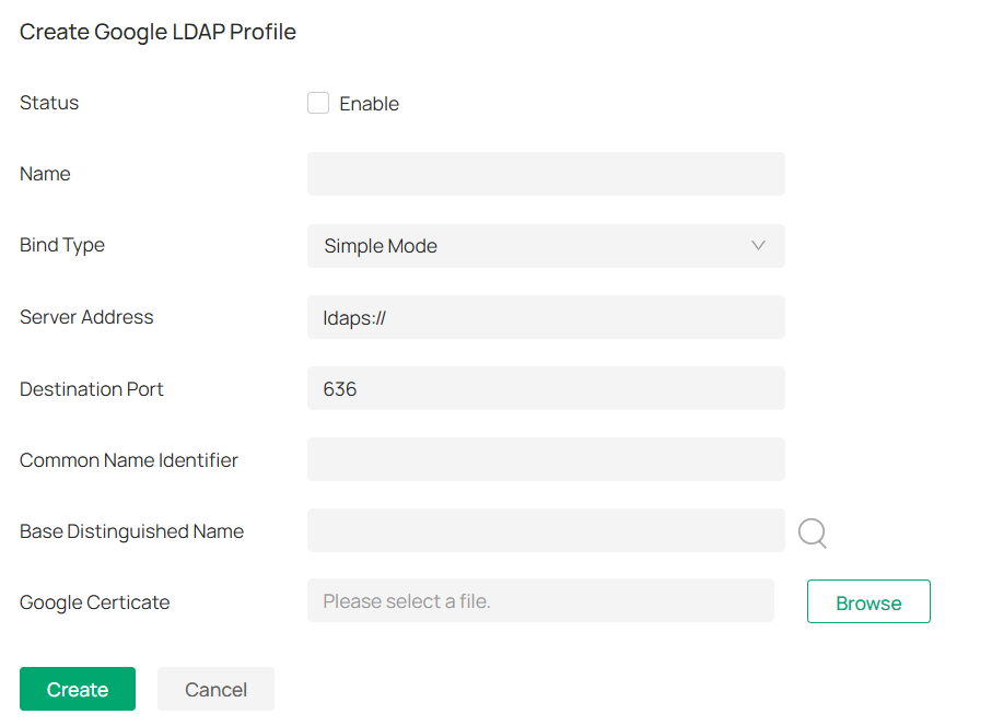
5. Configure the parameters.
|
Status |
Check the box to enable LDAP Authentication. |
|---|---|
|
Name |
Specify the profile name. |
|
Bind Type |
Select the LDAP Authentication mode: Simple Mode or Regular Mode. |
|
Server Address |
Enter the IP address of the LDAP server. |
|
Destination Port |
Enter the port ID of the LDAP server. By default, the port ID is 636. |
|
Common Name Identifier |
Specify the common name for user authentication. It is usually “uid”. Determine based on the actual situation of the directory. |
|
Base Distinguished Name |
Specify the user identifier for user authentication. You can click the icon next to it to search and select from the LDAP directory tree. |
|
Google Certificate |
Upload the Google certificate you downloaded. |
6. Click Apply to save the profile. Now you can select the predefined entry of LDAP profile when configuring rules of related modules like LDAP Server.
Configure APN Profiles
Overview
APN is a network access technology required when using the SIM card to access the internet. It determines which access method the SIM card uses to access the internet.
Configuration
To configure the APN profiles, follow these steps:
1. Launch the controller and access a site.
2. Go to Network Config > Profile > APN Profile. You can also go to Network Config > Network Settings > Internet > LTE if a LTE model has been adopted or pre-configured.
3. Click Create New APN Profile to add a new profile .

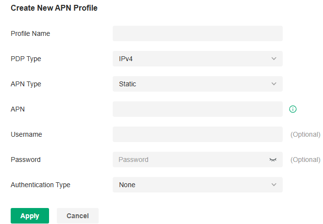
4. Configure the parameters.
|
Profile Name |
Specify the name of the profile. |
|---|---|
|
PDP Type |
Select the PDP (Packet Data Protocol) type: IPv4, IPv6, or IPv4 & IPv6. |
|
APN Type |
Select the APN type: Static or Dynamic. |
|
APN |
When APN Type is Static, specify the APN (access point name) provided by your ISP. |
|
Username |
Enter the username provided by your ISP. This field is case-sensitive. |
|
Password |
Enter the password provided by your ISP. This field is case-sensitive. |
|
Authentication Type |
Some ISPs need a specific authentication type, please confirm it with your ISP or keep the default value. None: No authentication is required. PAP: Password Authentication Protocol. The protocol allows a device to establish authentication with a peer using a two-way handshake. Select this option if your ISP requires this authentication type. CHAP: Challenge Handshake Authentication Protocol. The protocol allows a device to establish authentication with a peer using a three-way handshake and periodically checking the peer’s identity. Select this option if your ISP requires this authentication type. |
|
Apply to SIM |
(For models with dual SIM cards) Select the SIM card to which the APN profile will be applied. |
5. Click Apply to save the profile. Now you can select the predefined entry of APN profile when configuring rules of related modules.
Configuring Network Security
Network Security is a portfolio of features designed to improve the usability and ensure the safety of your network and data. It implements policies and controls on multiple layers of defenses in the network.
Configure ACL
Overview
ACL (Access Control List) allows a network administrator to create rules to restrict access to network resources. ACL rules filter traffic based on specified criteria such as source IP addresses, destination IP addresses, and port numbers, and determine whether to forward the matched packets. These rules can be applied to specific clients or groups whose traffic passes through the gateway, switches and APs.
The system filters traffic against the rules in the list sequentially. The first match determines whether the packet is accepted or dropped, and other rules are not checked after the first match. Therefore, the order of the rules is critical. By default, the rules are prioritized by their created time. The rule created earlier is checked for a match with higher priority. To reorder the rules, select a rule and drag it to a new position. If no rules match, the device forwards the packet because of an implicit Permit All clause.
The system provides three types of ACL:
■ Gateway ACL
After Gateway ACLs are configured on the controller, they can be applied to the gateway to control traffic which is sourced from LAN ports and forwarded to the WAN ports.
You can set the Network, IP address, port number of a packet as packet-filtering criteria in the rule.
■ Switch ACL
After Switch ACLs are configured on the controller, they can be applied to the switch to control inbound and outbound traffic through switch ports.
You can set the Network, IP address, port number and MAC address of a packet as packet-filtering criteria in the rule.
■ EAP ACL
After EAP ACLs are configured on the controller, they can be applied to the APs to control traffic in wireless networks.
You can set the Network, IP address, port number and SSID of a packet as packet-filtering criteria in the rule.
Configuration
To complete the ACL configuration, follow these steps:
1) Create an ACL with the specified type.
2) Define packet-filtering criteria of the rule, including protocols, source, and destination, and determine whether to forward the matched packets.
■ Configuring Gateway ACL
1. Launch the controller and access a site.
2. Go to Network Config > Security > ACL. On Gateway ACL tab, click Create New Rule to load the following page.

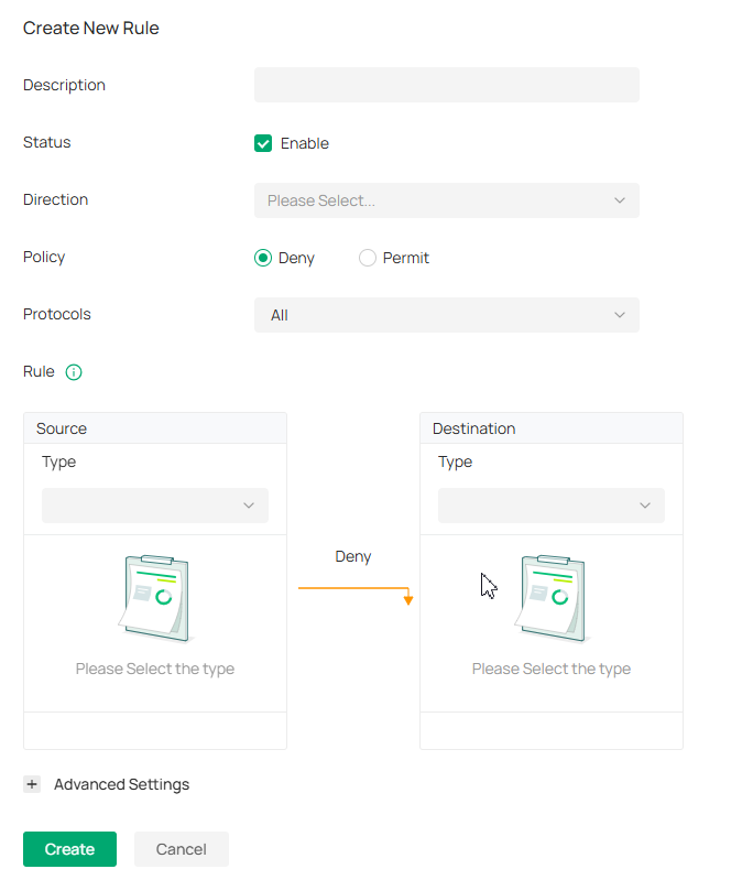
3. Define packet-filtering criteria of the rule, including protocols, source, and destination, and determine whether to forward the matched packets. Refer to the following table to configure the required parameters and click Create.
|
Description |
Enter a description to identify the ACL. |
|---|---|
|
Status |
Click the checkbox to enable the ACL. |
|
Direction |
Select the direction of ACL application traffic. LAN->LAN: Control packet forwarding between LAN side devices. LAN->WAN: Control packet forwarding in the LAN-WAN direction. [SFP WAN/LAN1] IN / [WAN2] IN / [USB Modem] IN: Control packet coming in from a specific WAN port. The options vary by model. |
|
Policy |
Select the action to be taken when a packet matches the rule. Permit: Forward the matched packet. Deny: Discard the matched packet. |
|
Protocols |
Select one or more protocol types to which the rule applies from the drop-down list. The default is All, indicating that packets of all protocols will be matched. When you select one of TCP and UDP or both of them, you can set the IP address and port number of a packet as packet-filtering criteria in the rule. |
From the Source drop-down list, choose one of these options to specify the source of the packets to which this ACL applies:
|
Network |
Select the network you have created. If no networks have been created, you can select the default network (LAN), or go to Network Config > Network Settings > LAN to create one. The gateway will examine whether the packets are sourced from the selected network. |
|---|---|
|
! Network |
Select a network you have created and the settings will not applied to that network. |
|
SSID |
Select the SSID you have created. If no SSIDs have been created, go to Network Config > Network Settings > WLAN to create one.The system will examine whether the SSID of the packet is the SSID selected here. |
|
IP Group |
Select the IP Group you have created. If no IP Groups have been created, click + Create on this page or go to Network Config > Profile > Groups to create one. The gateway will examine whether the source IP address of the packet is in the IP Group. |
|
! IP Group |
Select an IP group you have created and the settings will not applied to that IP group. |
|
IP-Port Group |
Select the IP-Port Group you have created. If no IP-Port Groups have been created, click + Create on this page or go to Network Config > Profile > Groups to create one. The gateway will examine whether the source IP address and port number of the packet are in the IP-Port Group. |
|
! IP-Port Group |
Select an IP-Port group you have created and the settings will not applied to that IP-Port group. |
|
IPv6 Group |
IPv6 Group:Select the IPv6 Group you have created. If no IPv6 Groups have been created, click + Create on this page or go to Network Config > Profile > Groups to create one. The system will examine whether the source IPv6 address of the packet is in the IPv6 Group. |
|
! IPv6 Group |
Select an IPv6 group you have created and the settings will not applied to that IPv6 group. |
|
IPv6-Port Group |
IPv6-Port Group:Select the IPv6-Port Group you have created. If no IPv6-Port Groups have been created, click + Create on this page or go to Network Config > Profile > Groups to create one. The system will examine whether the source IPv6 address and port number of the packet are in the IPv6-Port Group. |
|
! IPv6-Port Group |
Select an IPv6-Port group you have created and the settings will not applied to that IPv6-Port group. |
|
Location |
Select one or multiple locations from the list as the source address, and the system will judge whether the source IP of the data packet belongs to the selected locations. |
|
Location Group |
Select a location group you have created, and the system will judge whether the source IP of the data packet belongs to this location group. If no location group has been created, click the create button to create one, or go to Network Config > Profile > Groups to create one. |
From the Destination drop-down list, choose one of these options to specify the destination of the packets to which this ACL applies:
|
IP Group |
Select the IP Group you have created. If no IP Groups have been created, click + Create on this page or go to Network Config > Profile > Groups to create one. The gateway will examine whether the destination IP address of the packet is in the IP Group. |
|---|---|
|
! IP Group |
Select an IP group you have created and the settings will not applied to that IP group. |
|
IP-Port Group |
Select the IP-Port Group you have created. If no IP-Port Groups have been created, click + Create on this page or go to Network Config > Profile > Groups to create one. The gateway will examine whether the destination IP address and port number of the packet are in the IP-Port Group. |
|
! IP-Port Group |
Select an IP-Port group you have created and the settings will not applied to that IP-Port group. |
|
IPv6 Group |
Select the IPv6 Group you have created. If no IPv6 Groups have been created, click + Create on this page or go to Network Config > Profile > Groups to create one. The system will examine whether the destination IPv6 address of the packet is in the IPv6 Group. |
|
! IPv6 Group |
Select an IPv6 group you have created and the settings will not applied to that IPv6 group. |
|
IPv6-Port Group |
Select the IPv6-Port Group you have created. If no IPv6-Port Groups have been created, click + Create on this page or go to Network Config > Profile > Groups to create one. The system will examine whether the destination IPv6 address and port number of the packet are in the IPv6-Port Group. |
|
! IPv6-Port Group |
Select an IPv6-Port group you have created and the settings will not applied to that IPv6-Port group. |
|
Location |
Select one or multiple locations from the list as the destination address, and the system will judge whether the destination IP of the data packet belongs to the selected locations. |
|
Location Group |
Select a location group you have created, and the system will judge whether the destination IP of the data packet belongs to this location group. If no location group has been created, click the create button to create one, or go to Network Config > Profile > Groups to create one. |
|
Gateway Management Page |
This option will allow/block LAN network devices to access the gateway management page. |
|
Domain Group |
Select a domain group you have created, and the system will judge whether the destination domain of the data packet belongs to this domain group. If no domain group has been created, click the create button to create one, or go to Network Config > Profile > Groups to create one. |
Set the advanced settings according to your needs:
|
Time Range |
Select the checkbox to enable time-based ACL. You can create a time range or select an existing time range for the ACL rule to take effect. |
|---|---|
|
Bi-Directional |
When Direction is LAN->LAN, you can enable this option to configure bi-directional traffic rule. |
|
States Type |
Determine the type of stateful ACL rule. It is recommended to use the default Auto type. Auto (Match Sate New/Established/Related): Match the new, established, and related connection states. Manual: If selected, you can manually specify the connection states to match. Match State New: Match the connections of the initial state. For example, a SYN packet arrives in a TCP connection, or the router only receives traffic in one direction. Match State Established: Match the connections that have been established. In other words, the firewall has seen the bidirectional communication of this connection. Match State Invalid: Match the connections that do not behave as expected. Match State Related: Match the associated sub-connections of a main connection, such as a connection to a FTP data channel. |
■ Configuring Switch ACL
1. Launch the controller and access a site.
2. Go to Network Config > Security > ACL. Under the Switch ACL tab, click Create New Rule to load the following page.

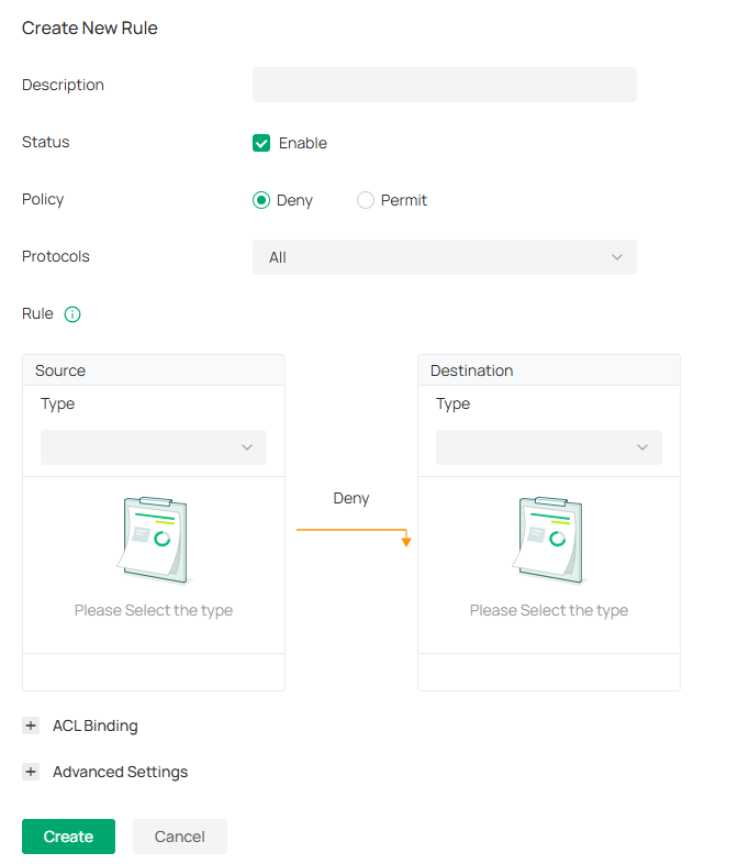
3. Define packet-filtering criteria of the rule, including protocols, source, and destination, and determine whether to forward the matched packets. Refer to the following table to configure the required parameters.
|
Description |
Enter a description to identify the ACL. |
|---|---|
|
Status |
Click the checkbox to enable the ACL. |
|
Policy |
Select the action to be taken when a packet matches the rule. Permit: Forward the matched packet. Deny: Discard the matched packet. |
|
Protocols |
Select one or more protocol types to which the rule applies from the drop-down list. The default is All, indicating that packets of all protocols will be matched. When you select one of TCP and UDP or both of them, you can set the IP address and port number of a packet as packet-filtering criteria in the rule. |
|
Time Range |
Select the checkbox to enable time-based ACL. You can create a time range or select an existing time range for the ACL rule to take effect. |
|
Ethertype |
Click the checkbox if you want the switch to check the ethertype of the packets, and configure the Ethertype based on needs. |
|
Bi-Directional |
Click the checkbox to enable the switch to create another symmetric ACL with the name “xxx_reverse”, where “xxx” is the name of the current ACL. The two ACLs target at packets with the opposite direction of each other. |
From the Source drop-down list, choose one of these options to specify the source of the packets to which this ACL applies:
|
Network |
Select the network you have created. If no networks have been created, you can select the default network (LAN), or go to Network Config > Network Settings > LAN to create one. The switch will examine whether the packets are sourced from the selected network. |
|---|---|
|
IP Group |
Select the IP Group you have created. If no IP Groups have been created, click + Create on this page or go to Network Config > Profile > Groups to create one. The switch will examine whether the source IP address of the packet is in the IP Group. |
|
IP-Port Group |
Select the IP-Port Group you have created. If no IP-Port Groups have been created, click + Create on this page or go to Network Config > Profile > Groups to create one. The switch will examine whether the source IP address and port number of the packet are in the IP-Port Group. |
|
MAC Group |
Select the MAC Group you have created. If no MAC Groups have been created, click + Create on this page or go to Network Config > Profile > Groups to create one. The switch will examine whether the source MAC address of the packet is in the MAC Group. |
|
IPv6 Group |
Select the IPv6 Group you have created. If no IPv6 Groups have been created, click + Create on this page or go to Network Config > Profile > Groups to create one. The switch will examine whether the source IP address of the packet is in the IPv6 Group. |
|
IPv6-Port Group |
Select the IPv6-Port Group you have created. If no IPv6-Port Groups have been created, click + Create on this page or go to Network Config > Profile > Groups to create one. The switch will examine whether the source IP address and port number of the packet are in the IPv6-Port Group. |
From the Destination drop-down list, choose one of these options to specify the destination of the packets to which this ACL applies:
|
Network |
Select the network you have created. If no networks have been created, you can select the default network (LAN), or go to Network Config > Network Settings > LAN to create one. The switch will examine whether the packets are forwarded to the selected network. |
|---|---|
|
IP Group |
Select the IP Group you have created. If no IP Groups have been created, click + Create on this page or go to Network Config > Profile > Groups to create one. The switch will examine whether the destination IP address of the packet is in the IP Group. |
|
IP-Port Group |
Select the IP-Port Group you have created. If no IP-Port Groups have been created, click + Create on this page or go to Network Config > Profile > Groups to create one. The switch will examine whether the destination IP address and port number of the packet are in the IP-Port Group. |
|
MAC Group |
Select the MAC Group you have created. If no MAC Groups have been created, click + Create on this page or go to Network Config > Profile > Groups to create one. The switch will examine whether the destination MAC address of the packet is in the MAC Group. |
|
IPv6 Group |
Select the IPv6 Group you have created. If no IPv6 Groups have been created, click + Create on this page or go to Network Config > Profile > Groups to create one. The switch will examine whether the destination IP address of the packet is in the IPv6 Group. |
|
IPv6-Port Group |
Select the IPv6-Port Group you have created. If no IPv6-Port Groups have been created, click + Create on this page or go to Network Config > Profile > Groups to create one. The switch will examine whether the destination IP address and port number of the packet are in the IPv6-Port Group. |
4. Bind the switch ACL to a switch port or a VLAN and click Create. Note that a switch ACL takes effect only after it is bound to a port or VLAN.
|
Binding Type |
Specify whether to bind the ACL to ports or a VLAN. Ports: Select All Ports or Custom Ports as the interfaces to be bound with the ACL. With All ports selected, the rule is applied to all ports of the switch. With Custom ports selected, the rule is applied to the selected ports of the switch. Click the ports from the Device List to select the binding ports.
VLAN: Select a VLAN and specify the switches as the interface to be bound with the ACL. If no VLANs have been created, you can select the default VLAN 1 (LAN), or go to Network Config > Network Settings > LAN to create one. |
|---|


■ Configuring EAP ACL
1. Launch the controller and access a site.
2. Go to Network Config > Security > ACL. Under the E tab, click Create New Rule to load the following page.

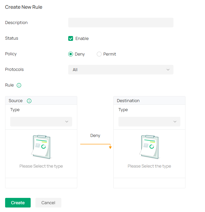
3. Define packet-filtering criteria of the rule, including protocols, source, and destination, and determine whether to forward the matched packets. Refer to the following table to configure the required parameters and click Create.
|
Description |
Enter a description to identify the ACL. |
|---|---|
|
Status |
Click the checkbox to enable the ACL. |
|
Policy |
Select the action to be taken when a packet matches the rule. Permit: Forward the matched packet. Deny: Discard the matched packet. |
|
Protocols |
Select one or more protocol types to which the rule applies from the drop-down list. The default is All, indicating that packets of all protocols will be matched. When you select one of TCP and UDP or both of them, you can set the IP address and port number of a packet as packet-filtering criteria in the rule. |
From the Source drop-down list, choose one of these options to specify the source of the packets to which this ACL applies:
|
Network |
Select the network you have created. If no networks have been created, you can select the default network (LAN), or go to Network Config > Network Settings > LAN to create one. The AP will examine whether the packets are sourced from the selected network. |
|
IP Group |
Select the IP Group you have created. If no IP Groups have been created, click + Create on this page or go to Network Config > Profile > Groups to create one. The AP will examine whether the source IP address of the packet is in the IP Group. |
|
IP-Port Group |
Select the IP-Port Group you have created. If no IP-Port Groups have been created, click + Create on this page or go to Network Config > Profile > Groups to create one. The AP will examine whether the source IP address and port number of the packet are in the IP-Port Group. |
|
SSID |
Select the SSID you have created. If no SSIDs have been created, go to Network Config > Network Settings > WLAN to create one. The AP will examine whether the SSID of the packet is the SSID selected here. |
|
IPv6 Group |
Select the IPv6 Group you have created. If no IPv6 Groups have been created, click +Create on this page or go to Network Config > Profile > Groups to create one. The AP will examine whether the source IP address of the packet is in the IPv6 Group. |
|
IPv6-Port Group |
Select the IPv6-Port Group you have created. If no IPv6-Port Groups have been created, click + Create on this page or go to Network Config > Profile > Groups to create one. The AP will examine whether the source IP address and port number of the packet are in the IPv6-Port Group. |
From the Destination drop-down list, choose one of these options to specify the destination of the packets to which this ACL applies:
|
Network |
Select the network you have created. If no networks have been created, you can select the default network (LAN), or go to Network Config > Network Settings > LAN to create one. The AP will examine whether the packets are forwarded to the selected network. |
|
IP Group |
Select the IP Group you have created. If no IP Groups have been created, click + Create on this page or go to Network Config > Profile > Groups to create one. The AP will examine whether the destination IP address of the packet is in the IP Group. |
|
IP-Port Group |
Select the IP-Port Group you have created. If no IP-Port Groups have been created, click + Create on this page or go to Network Config > Profile > Groups to create one. The AP will examine whether the destination IP address and port number of the packet are in the IP-Port Group. |
|
IPv6 Group |
Select the IPv6 Group you have created. If no IPv6 Groups have been created, click + Create on this page or go to Network Config > Profile > Groups to create one. The AP will examine whether the destination IP address of the packet is in the IPv6 Group. |
|
IPv6-Port Group |
Select the IPv6-Port Group you have created. If no IPv6-Port Groups have been created, click + Create on this page or go to Network Config > Profile > Groups to create one. The AP will examine whether the destination IP address and port number of the packet are in the IPv6-Port Group. |
Configure URL Filtering
Overview
URL Filtering allows a network administrator to create rules to block or allow certain websites, which protects it from web-based threats, and deny access to malicious websites.
In URL filtering, the system compares the URLs in HTTP, HTTPS and DNS requests against the lists of URLs that are defined in URL Filtering rules, and intercepts the requests that are directed at a blocked URLs. These rules can be applied to specific clients or groups whose traffic passes through the gateway and APs.
The system filters traffic against the rules in the list sequentially. The first match determines whether the packet is accepted or dropped, and other rules are not checked after the first match. Therefore, the order of the rules is critical. By default, the rules are prioritized based on the sequence they are created. The rule created earlier is checked for a match with a higher priority. To reorder the rules, select a rule and drag it to a new position. If no rules match, the device forwards the packet because of an implicit Permit All clause.
Note that URL Filtering rules take effects with a higher priority over ACL rules. That is, the system will process the URL Filtering rule first when the URL Filtering rule and ACL rules are configured at the same time.
Configuration
To complete the URL Filtering configuration, follow these steps:
1) Create a new URL Filtering rule with the specified type.
2) Define filtering criteria of the rule, including source, and URLs, and determine whether to forward the matched packets.
■ Configuring Gateway Rules
1. Launch the controller and access a site.
2. Go to Network Config > Security > URL Filtering.
3. Under the Gateway Rules tab, configure the parameters.

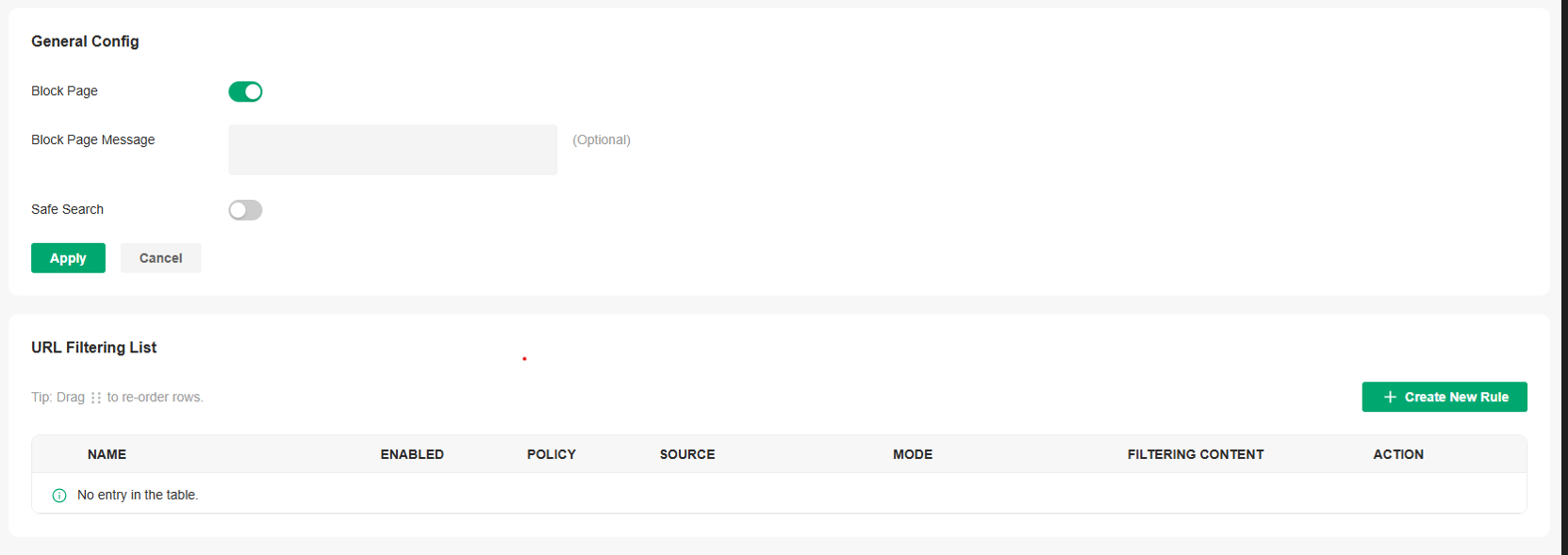
|
Block Page |
When enabled, users attempting to access blocked websites will be redirected to a specific page indicating that the website is blocked by access policy. |
|---|---|
|
Block Page Message |
When a user tries to access a blocked URL, the block page message will display to tell why access is denied. This can effectively remind users to comply with network usage regulations. |
|
Safe Search |
Check this option to enable Safe Search globally. This feature can filter search results to block inappropriate content. It is suitable for family and educational environments. |
4. Click Create New Rule to load the following page.

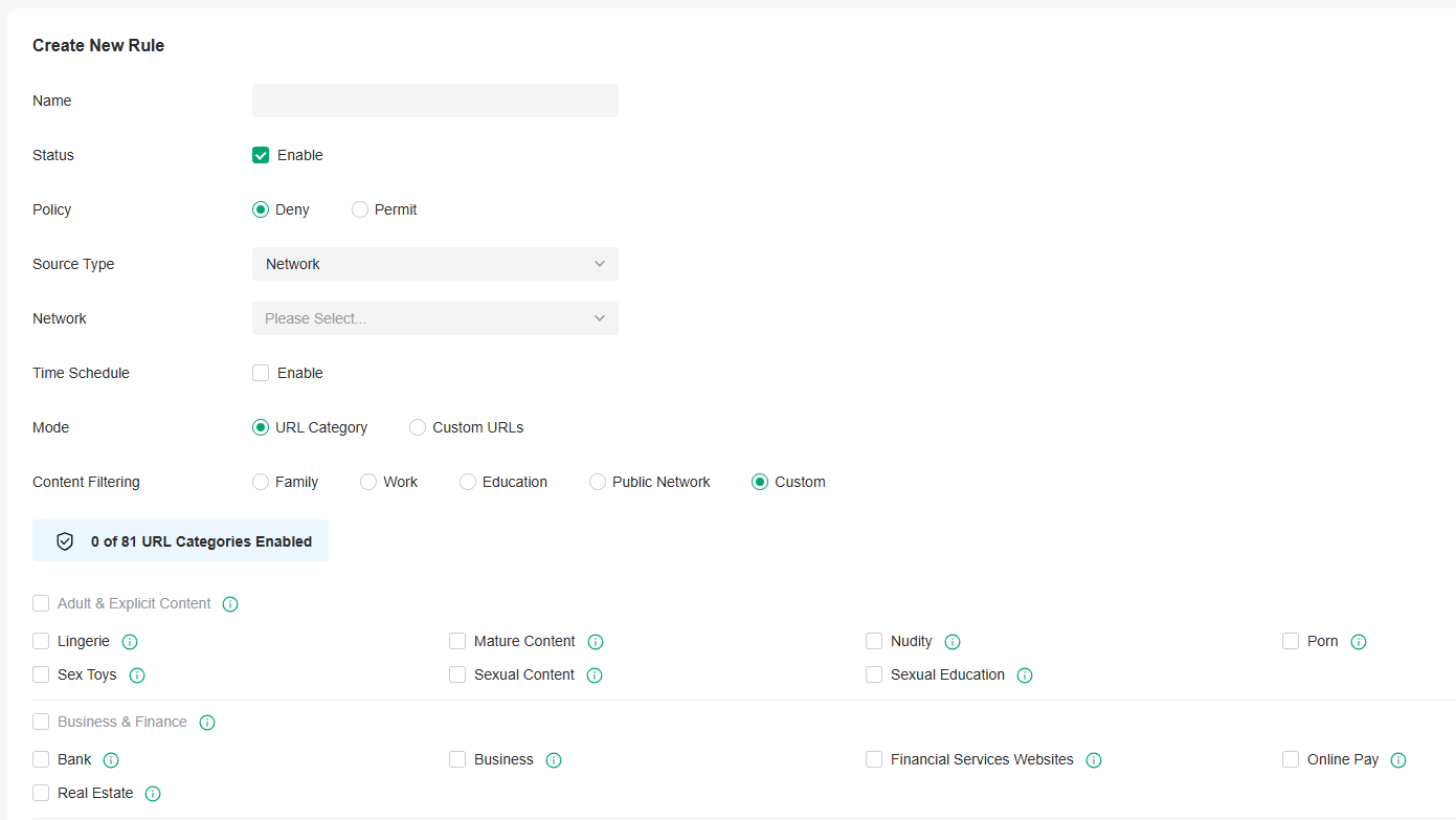
5. Define filtering criteria of the rule, including source and URLs, and determine whether to forward the matched packets. Refer to the following table to configure the required parameters and click Save.
|
Name |
Enter a name to identify the URL Filtering rule. |
|---|---|
|
Status |
Click the checkbox to enable the URL Filtering rule. |
|
Policy |
Select the action to be taken when a packet matches the rule. Deny: Discard the matched packet and the clients cannot access the URLs. Permit: Forward the matched packet and clients can access the URLs. |
|
Source Type |
Select the source of the packets to which this rule applies. Network: With Network selected, select the network you have created from the Network drop-down list. If no networks have been created, you can select the default network (LAN), or go to Network Config > Network Settings > LAN to create one. The gateway will filter the packets sourced from the selected network. IP Group: With IP Group selected, select the IP Group you have created from the IP Group drop-down list. If no IP Groups have been created, click + Create New IP Group on this page or go to Network Config > Profile > Groups to create one. The gateway will examine whether the source IP address of the packet is in the IP Group. |
|
Time Schedule |
Enable this option and set a time schedule if needed. |
|
Mode |
Choose a mode for the filtering content to match the URL. URL Category: Frequently used URLs such as news, entertainment, and shopping are divided into different categories. This mode is suitable for most common scenarios, but if you find that the required URLs are not in the filtering category, you can add the specific URLs in the custom URL mode. |
|
Content Filtering |
Select a preset scenario. |
■ Configuring AP Rules
1. Launch the controller and access a site.
2. Go to Network Config > Security > URL Filtering. On EAP Rules tab, click Create New Rule to load the following page.

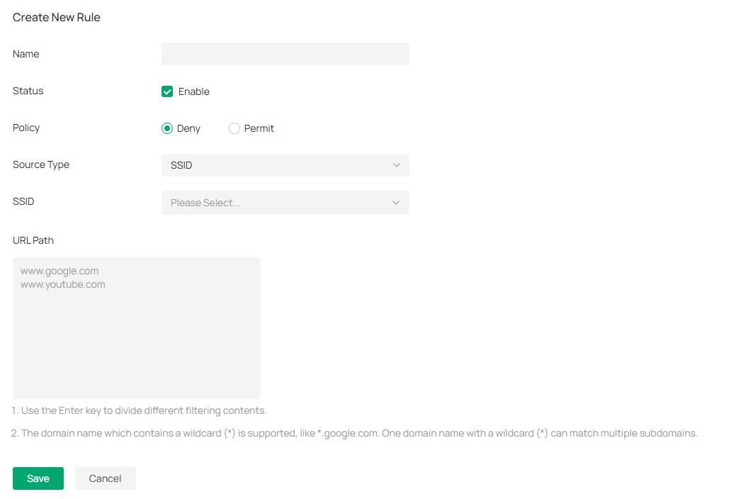
3. Define filtering criteria of the rule, including source and URLs, and determine whether to forward the matched packets. Refer to the following table to configure the required parameters and click Save.
|
Name |
Enter a name to identify the URL Filtering rule. |
|---|---|
|
Status |
Click the checkbox to enable the URL Filtering rule. |
|
Policy |
Select the action to be taken when a packet matches the rule. Deny: Discard the matched packet and the clients cannot access the URLs. Permit: Forward the matched packet and clients can access the URLs. |
|
Source Type |
Select the SSID of the packets to which this rule applies. |
|
URL Path |
Enter the URL address using up to 128 characters. URL address should be given in a valid format. The URL which contains a wildcard(*) is supported. One URL with a wildcard(*) can match mutiple subdomains. For example, with *.tp-link.com specified, community.tp-link.com will be matched. |
Configure Application Control
Overview
DPI (Deep Packet Inspection) helps you identify, analyze, and control the traffic at the application layer in the network. DPI engine includes the latest application identification signatures to track which applications are using the most bandwidth. You can better manage and distribute network traffic usage through DPI.
Configuration
1. Launch the controller and access a site.
2. Go to Network Config > Security > Application Control.
3. On the Deep Packet Inspection page, enable Deep Packet Inspection and Logging Traffic, then apply the settings.

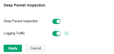
|
Deep Packet Inspection |
When enabled, the device will send the forwarded traffic to a professional local DPI engine for analysis, so as to judge and identify the type of traffic. |
|---|---|
|
Logging Traffic |
When enabled, the device will collect and save the results of traffic analysis. You can check the results on the Insights > Application Analytics page. |
4. Apply the settings.
5. On the Rules Management page, click Create New Rule. You can predefine one or more rules, and APP control strategy that can be referenced, and realize block or QoS actions for specified Apps within a specified time period.

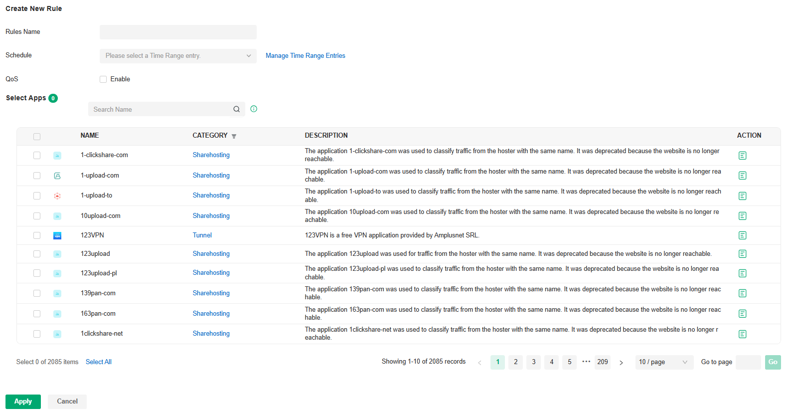
|
Rule Name |
Specify the name of the rule. |
|---|---|
|
Schedule |
Specify the time period when the rule takes effect. You can create new time range according to your needs. |
|
QoS |
Enable this option and select QoS Class to configure the QoS strategy if needed. When enabled, the traffic will be limited according to the configuration. When disabled, the App will be blocked. |
|
Select Apps |
Select the Apps for the rule. |
6. On the Application Filter page, click Create New Application Filter. You can apply the defined rules and divide multiple rules into one filter set for easy management.

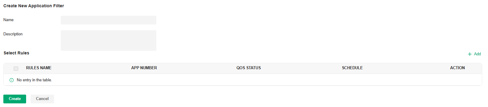
|
Name |
Specify the name of the filter. |
|---|---|
|
Description |
Enter a description for identification. |
|
Select Rules |
Select the rules for the filter. |
7. On the Deep Packet Inspection page, click Create New Assign Restriction. Select a network to apply a pre-defined filter.

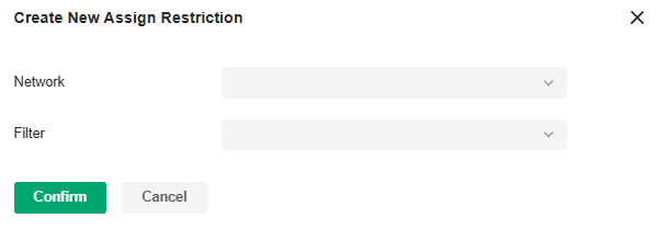
|
Network |
Select a network to apply the filter. |
|---|---|
|
Filter |
Select a pre-defined filter. |
8. Save the settings. You can view the results of traffic analysis on the Insights > Application Analytics page.


If you want to clear DPI data of a time period, go to the Deep Packet Inspection page, click the Clear Data button and specify the period.
Configure IDS/IPS for Threat Management
IDS/IPS is a security mechanism that detects intrusions based on attack characteristics. It can detect malware, Trojan horses, worms, ActiveX and other attacks to protect the network security of users.
Note:
Using Intrusion Detection/Prevention may reduce maximum throughput speeds.
Configure IDS/IPS
1. Launch the controller and access a site.
2. Go to Network Config > Security > IDS/IPS.
3. Enable Intrusion Detection/Prevention and configure the parameters.

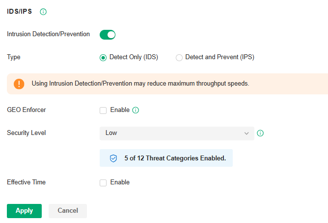
|
Type |
Specify the working mode. In IDS mode, the system will only report the threat log. In IPS mode, the system will block the corresponding connection for 300s after a threat is detected. |
|---|---|
|
GEO Enforcer |
Enable geographic location identification of threat logs. |
|
Security Level |
Choose the protection level. A higher protection level means more threat types are detected, while a lower protection level only detects some important threats. You can also customize the protection level. |
|
Effective Time |
Specify the effective time period of the IDS/IPS module. |
4. Apply the settings.
When the system discovers a threat, the corresponding threat log will be displayed on the Threat Management page in the current site and the Security page in Global View.
Manage Threats in a Site
1. Launch the controller and access a site.
2. Go to Network Config > Security > IDS/IPS > Threat Management.
3. Click a threat that the system discovered, then you can choose a specified response strategy for the corresponding attack IP: Block, Isolate Device, Signature Suppression, or Allow.

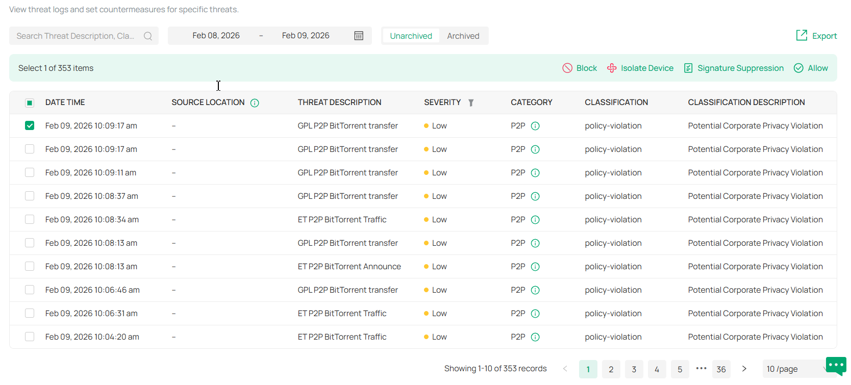
|
Block |
Drop traffic to/from the external IP address and the specific internal IP address. If you block an entry, it will be added to the Block List at Network Config > Security > IDS/IPS. |
|---|---|
|
Isolate Device |
Drop traffic to/from the external IP address and any internal IP address. |
|
Signature Suppression |
Mute the alerting on certain signatures. This will also disable blocking on traffic matching the designated suppression rule. If you suppress the signature of an entry, it will be added to the Signature Suppression list at Network Config > Security > IDS/IPS. |
|
Allow |
Trust the IP address so that the traffic, depending on the direction selected, will not get blocked to or from the identified IP address. If you allow an entry, it will be added to the Allow List at Network Config > Security > IDS/IPS. |
4. You can further check and edit processed entries at Network Config > Security > IDS/IPS.
■ Block List
The Block List page displays all block entries added through the Threat Management page. You can choose to block all traffic of the source IP in the threat log, or block all traffic between the source IP and the destination IP in the threat log.
■ Allow List
On the Allow List page, you can add, view, and edit the exemption entries of IDS/IPS detection, so that the specified objects will no longer trigger threat logs.
Click Create New Allow List and configure the parameters.

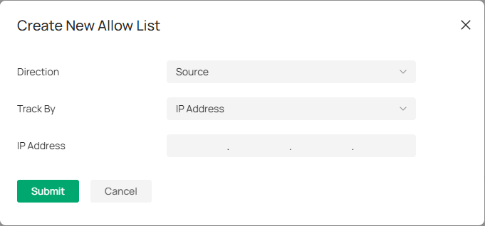
|
Direction |
Specify the location of the object (target) exempt from triggering the threat: source, destination, or both directions. |
|---|---|
|
Track By |
Specify the type of object (target) exempt from triggering the threat: IP address, Network, or Subnet. |
|
IP Address/Network/Subnet |
Specify the value of the object. |
■ Signature Suppression
The Signature Suppression page displays all the signature suppression entries added through the Threat Management page, and the objects with signature suppressed will no longer trigger specific threat logs.
Manage Threats Globally
The Security page allows you to manage threats that the controller discovered to ensure network security.
To manage threats globally, go to Security in Global view. You can manage threats in a list or map.
■ Threat Management List
In the Threat Management List, you can check top threats by severity, locations of top threats, and unarchived and archived threats.

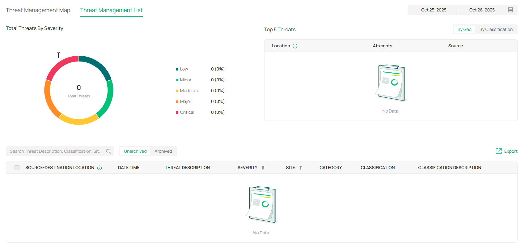
In the unarchived threat list, click an entry, then you can choose a specified response strategy for the corresponding attack IP: Block, Isolate Device, Signature Suppression, or Allow.
|
Block |
Drop traffic to/from the external IP address and the specific internal IP address. If you block an entry, it will be added to the Block List at Network Config > Security > IDS/IPS. |
|---|---|
|
Isolate Device |
Drop traffic to/from the external IP address and any internal IP address. |
|
Signature Suppression |
Mute the alerting on certain signatures. This will also disable blocking on traffic matching the designated suppression rule. If you suppress the signature of an entry, it will be added to the Signature Suppression list at Network Config > Security > IDS/IPS. |
|
Allow |
Trust the IP address so that the traffic, depending on the direction selected, will not get blocked to or from the identified IP address. If you allow an entry, it will be added to the Allow List at Network Config > Security > IDS/IPS. |
■ Threat Management Map
In the Threat Management Map, you can view the threat sources and numbers of attacks that the system has discovered. You can click a number in the map to view attack details.
You can right-click a location to block its attack events and manage the Block Locations list.
If excessive attacks have been detected, you can choose specific severity levels to display.

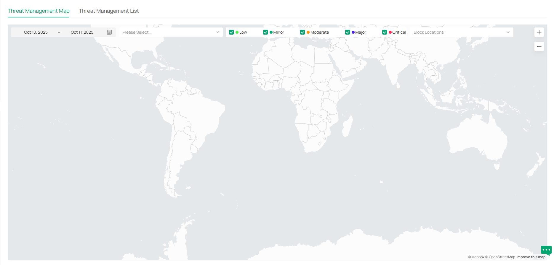
Configure the Firewall
Overview
Firewall is used to enhance the network security.
In State Timeouts, you can specify a number of timeouts for sessions including TCP, UDP, and ICMP connection. The packets will be forwarded within the specified timeout. When there is no response after the specified time, the session or status will be closed. State timeout will help close inactive sessions and thus avoid network malfunction.
In Firewall Options, you can further configure the gateway to prevent attacks like SYN flood attacks and broadcast ping.
Configuring State Timeouts
1. Launch the controller and access a site.
2. Go to Network Config > Security > Firewall.
3. In the Sate Timeouts, set the time limit for the different sessions.

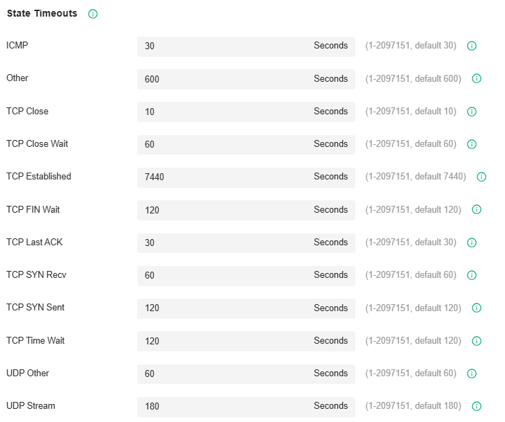
|
ICMP |
The ICMP session will be closed if there is no response after the set time. |
|---|---|
|
Other |
The sessions for protocols excluding TCP, UDP, and ICMP will be closed if there is no response after the set time. |
|
TCP Close |
The TCP Close status will be closed if there is no response after the set time. |
|
TCP Close Wait |
The TCP Close Wait status will be closed if there is no response after the set time. |
|
TCP Established |
The TCP Established status will be closed if there is no response after the set time. |
|
TCP FIN Wait |
The TCP FIN Wait status will be closed if there is no response after the set time. |
|
TCP Last ACK |
The TCP Last ACK status will be closed if there is no response after the set time. |
|
TCP SYN Recv |
The TCP SYN (Synchronize) Recv status will be closed if there is no response after the set time. |
|
TCP SYN Sent |
The TCP SYN (Synchronize) Sent status will be closed if there is no response after the set time. |
|
TCP Time Wait |
The TCP Time Wait status will be closed if there is no response after the set time. |
|
UDP Other |
The UDP connections with traffic in only one direction will be stopped if there is no response after the set time. |
|
UDP Stream |
The UDP connections with bidirectional traffic will be stopped if there is no response after the set time. |
Configuring Firewall Options
1. Launch the controller and access a site.
2. Go to Network Config > Security > Firewall.
3. In the Firewall Options, set the time limit for the different sessions.

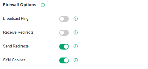
|
Broadcast Ping |
With it enabled, the gateway will reply to broadcast pings. |
|---|---|
|
Receive Redirects |
With it enabled, the gateway will accept ICMP redirects. |
|
Send Redirects |
With it enabled, the gateway will send ICMP redirects. |
|
SYN Cookies |
With it enabled, the SYN cookies will be used to resist SYN flood attacks that want to open ports on the gateway. |
Configure Attack Defense
Overview
Attacks initiated by utilizing inherent bugs of communication protocols or improper network deployment have negative impacts on networks. In particular, attacks on a network device can cause the device or network paralysis.
With the Attack Defense feature, the gateway can identify and discard various attack packets in the network, and limit the packet receiving rate. In this way, the gateway can protect itself and the connected network against malicious attacks.
The gateway provides two types of Attack Defense:
■ Flood Defense
If an attacker sends a large number of fake packets to a target device, the target device is busy with these fake packets and cannot process normal services. Flood Defense detects flood packets in real time and limits the receiving rate of the packets to protect the device.
Flood attacks include TCP SYN flood attacks, UDP flood attacks, and ICMP flood attacks.
■ Packet Anomaly Defense
Anomalous packets are packets that do not conform to standards or contain errors that make them unsuitable for processing. Packet Anomaly Defense discards the illegal packets directly.
Configuring Flood Defense
1. Launch the controller and access a site.
2. Go to Network Config > Security > Firewall > Attack Defense.
3. In the Flood Defense, click the checkbox and set the corresponding limit of the rate at which specific packets are received.

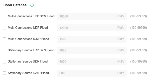
|
Multi-Connections TCP SYN Flood |
A TCP SYN flood attack occurs when the attacker sends the target system with a succession of SYN (synchronize) requests. When the system responds, the attacker does not complete the connections, thus leaving the connection half-open and flooding the system with SYN messages. No legitimate connections can then be made. With this feature enabled, the gateway limits the rate of receiving TCP SYN packets from all the clients to the specified rate. |
|---|---|
|
Multi-Connections UDP Flood |
A UDP flood attack occurs when the attacker sends a large number of UDP packets to a target host in a short time, the target host is busy with these UDP packets and cannot process normal services. With this feature enabled, the gateway limits the rate of receiving UDP packets from all the clients to the specified rate. |
|
Multi-Connections ICMP Flood |
If an attacker sends many ICMP Echo messages to the target device, the target device is busy with these Echo messages and cannot process other data packets. Therefore, normal services are affected. With this feature enabled, the system limits the rate of receiving ICMP packets from all the clients to the specified rate. |
|
Stationary Source TCP SYN Flood |
A TCP SYN flood attack occurs when the attacker sends the target system with a succession of SYN (synchronize) requests. When the system responds, the attacker does not complete the connections, thus leaving the connection half-open and flooding the system with SYN messages. No legitimate connections can then be made. With this feature enabled, the gateway limits the rate of receiving TCP SYN packets from a single client to the specified rate. |
|
Stationary Source UDP Flood |
A UDP flood attack occurs when the attacker sends a large number of UDP packets to a target host in a short time, the target host is busy with these UDP packets and cannot process normal services. With this feature enabled, the gateway limits the rate of receiving UDP packets from a single client to the specified rate. |
|
Stationary Source ICMP Flood |
If an attacker sends many ICMP Echo messages to the target device, the target device is busy with these Echo messages and cannot process other data packets. Therefore, normal services are affected. With this feature enabled, the system limits the rate of receiving ICMP packets from a single clients to the specified rate. |
Configuring Packet Anomaly Defense
1. Launch the controller and access a site.
2. Go to Network Config > Security > Firewall > Attack Defense.
3. In the Packet Anomaly Defense, click the checkbox and set the corresponding limit of the rate at which specific packets are received.

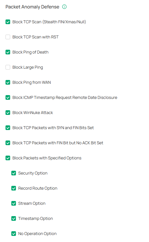
|
Block TCP Scan (Stealth FIN/Xmas/Null) |
With this option enabled, the gateway will block the anomalous packets in the following attack scenarios: Stealth FIN Scan: The attacker sends the packet with its SYN field and the FIN field set to 1. The SYN field is used to request initial connection whereas the FIN field is used to request disconnection. Therefore, the packet of this type is illegal. Xmas Scan: The attacker sends the illegal packet with its TCP index, FIN, URG and PSH field set to 1. Null Scan: The attacker sends the illegal packet with its TCP index and all the control fields set to 0. During the TCP connection and data transmission, the packets with all control fields set to 0 are considered illegal. |
|---|---|
|
Block TCP Scan with RST |
With this option enabled, the gateway will respond to RST messages. It is disabled by default. |
|
Block Ping of Death |
With this option enabled, the gateway will block Ping of Death attack. Ping of Death attack means that the attacker sends abnormal ping packets which are smaller than 64 bytes or larger than 65535 bytes to cause system crash on the target computer. |
|
Block Large Ping |
With this option enabled, the router will block the ping packets which are larger than the specified value (1024 packets by default) to protect the system from Large Ping attack. |
|
Block Ping from WAN |
With this option enabled, the router will block the ICMP request from WAN. |
|
Block ICMP Timestamp Request Remote Date Disclosure |
With this option enabled, the device will block all ICMP Timestamp (Type 13) packets. |
|
Block WinNuke Attack |
With this option enabled, the router will block WinNuke attacks. WinNuke attack refers to a remote DoS (denial-of-service) attack that affects some Windows operating systems, such as the Windows 95. The attacker sends a string of OOB (Out of Band) data to the target computer on TCP port 137, 138 or 139, causing system crash or Blue Screen of Death. |
|
Block TCP Packets with SYN and FIN Bits Set |
With this option enabled, the router will filter the TCP packets with both SYN Bit and FIN Bit set. |
|
Block TCP Packets with FIN Bit but No ACK Bit Set |
With this option enabled, the router will filter the TCP packets with FIN Bit set but without ACK Bit set. |
|
Block Packets with Specified Options |
With this option enabled, the router will filter the packets with specified IP options including Security Option, Loose Source Route Option, Strict Source Route Option, Record Route Option, Stream Option, Timestamp Option, and No Operation Option. You can choose the options according to your needs. |
Managing Network Devices
This chapter briefly introduces the management pages of controller-managed devices, including the gateway, switches, APs, and OLTs.
Manage the Device List
The Omada Controller provides 100% centralized management of Omada network devices, including gateways, switches, access points, OLTs, and more.
To manage network devices, go to Devices > Device List in Global View or Site View. In Global View, network devices of all sites will be listed; in Site view, network device of the current site will be listed.
You can manage the network devices in the list and manage each device in its Properties window and Device Management window.
For an easy monitoring of the devices, you can customize the column and filter the devices for a better overview of device information. Also, quick operations and Batch Edit are available for configurations.

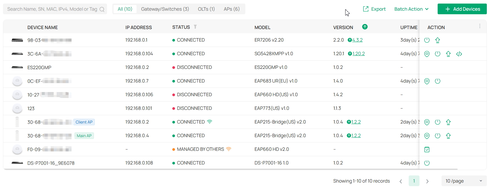
Monitor Connection Status
The Status column explains the connection status of devices.
Customize the Column
To customize the columns, click the ellipsis icon next to Action and check the boxes of information type.
To change the list order, click the upside-down triangle icon next to the column head, which indicates the ascending or descending order.
Filter the Devices
Use the search box and tab bar above the table to filter the devices.
To search for devices, enter the text in the search box.
To filter the devices, a tab bar is above the table to filter the devices by device type. You can also filter the devices by their status by clicking the filter icon in the Status column.
Quick Operations
Click the icons in the table header or the Action column to quickly operate the device.
|
|
Click to check if there is new firmware for the managed devices. |
|---|---|
|
|
(For pending devices) Click to adopt the device. |
|
|
(For connected switches and APs) Click this icon and the LEDs of the device will flash to indicate the device’s location. The LEDs will keep flashing for 10 minutes, or you can click the |
|
|
(For connected devices) Click to reboot the device. |
|
|
Click to upgrade the device’s firmware version. This icon appears when the device has a new firmware version. |
|
|
Displays the current running configuration. Operators or Administrators or local user group members with execution rights for this command. |
| (Only for the Main AP) Click to change the AP's role to a Client AP. |
|
| (Only for the Main AP) Click to move the APs in the current bridge group to another site. Note: Bridge APs only support the Move to Site function on the Bridge Group page. |
Batch Action
You can adopt devices in batches and configure the same type of devices in batches. Batch Config is available only for the devices in Preconfigured/Connected/Disconnected/Heartbeat Missed/Isolated status, while Batch Adopt is available for the devices in the Pending/Managed By Others status.

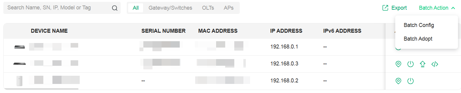
To batch adopt devices, click Batch Action > Batch Adopt, select devices, and click Adopt. If the selected devices are all in the Pending status, the controller will adopt then with the default username and password. If not, enter the username and password manually to adopt the devices.
To batch configure devices, click Batch Action > Batch Config, select devices, and click an action. You can batch configure device settings, perform custom upgrade, move them to a site, or forget them.
Manage a Device
Launch the controller and access a site. Go to Devices > Device List. In the device list, click a device, then you can monitor and manage it in the Properties window and Device Management window.
Properties Window
The Properties window displays the device status, port status, connection information, and other device information.
Note: The available functions in the window may vary by device type, model, and status.

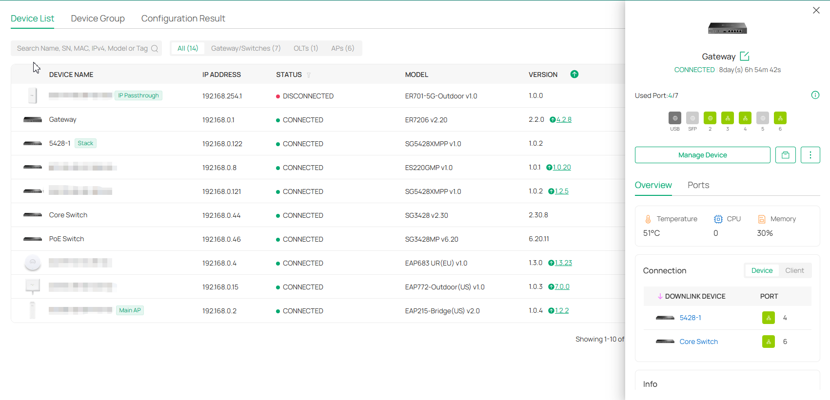
Quick Operations
Click the ![]()
![]() icon and choose an operation to quickly operate the device.
icon and choose an operation to quickly operate the device.
Note: The available functions may vary by device type, model, and status.
|
Custom Upgrade |
Click Browse and choose a file from your computer to upgrade the device. After upgraded, the device will reboot and be readopted by the controller. |
|---|---|
|
Copy Configuration |
Select another device at the current site to copy its configurations. Note: Only devices of the same model as the current device will be displayed. |
|
Download Device Info |
If the device has an abnormality, you can download the device information and provide it to our R&D personnel to analyze the problem. Note: Firmware updates are required for earlier devices to obtain complete information. |
|
Move to Site |
Select a site which the device will be moved to. After moving to another site, device configurations on the prior site will be replaced by that on the new site, and its traffic history will be cleared. |
|
Force Provision |
Click Force Provision to synchronize the configurations of the device with the controller. The device will lose connection temporarily, and be adopted to the controller again to get the configurations from the controller. |
|
Forget This Device |
Click Forget and then the device will be removed from the controller. Once forgotten, all configurations and history related to the device will be wiped out. |
|
IntelliRecover |
(Only for the EAP directly connected to the PoE switch) Click to enable the IntelliRecover function for the device so that it can be added to the IntelliRecover monitoring list. IntelliRecover can help you monitor the status of PoE devices, automatically repairing abnormal devices. |
|
ISP Upgrade |
(Only for 4G gateways) Click Browse to select the ISP upgrade file and click Upgrade to upgrade the ISP information. You can download the latest ISP upgrade file from https://support.omadanetworks.com. |
Network Tools
Click the ![]()
![]() icon and choose a network tool to analyze the network.
icon and choose a network tool to analyze the network.
Note: The available tools may vary by device type, model, and status.
|
Network Check |
Test the device connectivity via ping or traceroute. |
|---|---|
|
Terminal |
Open Terminal to execute CLI or Shell commands. |
|
Cable Test |
Perform cable test to check cable issues. |
|
Packet Capture |
Capture packets for network troubleshooting. |
|
Link Speed Test |
(Only for Bridge APs supporting link speed test and already form a bridge group) Click to test the link speed between the Main AP and Client AP. |
Device Management Window
Click Manage Device to open the Device Management window to view more device details and change device settings.
In the management window, you can click + and select one or more devices to open new management windows, click the 
 icon in the top left to minimize the windows to the
 icon in the right side, and click the icon to reopen the minimized windows.
You can also click each tab to monitor and manage the device.
Note: The available tabs and configurations may vary by device type, model, and status.

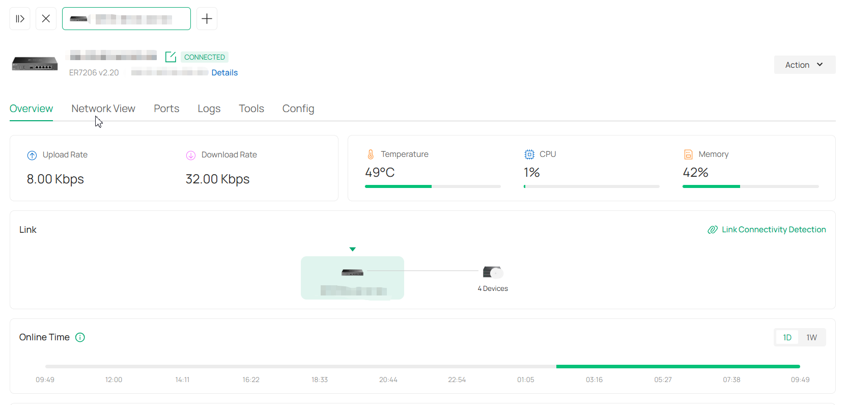
For detailed management, refer to the relevant User Guides:
■ Manage the Gateway via the Omada Controller
■ Manage Switches via the Omada Controller
■ Manage APs via the Omada Controller
■ Manage the OLT via the Omada Controller
Create and Manage Stack Groups
Introduction to Stack
Stack is a device virtualization technology that connects two and above switches supporting stack features via Ethernet cables through their stack ports, which logically virtualize them to one device as a whole to forward data in the network. Through this feature, switches can be stacked to improve reliability, expand port numbers, increase bandwidth, simplify networking, and etc.
In a stack system, the switches can be categorized mainly into two roles:
• Master Switch
A stack system has only one master switch. It manages and controls devices in the whole stack system.
• Member Switch
A stack system may have one or several member switches. They only forward data as standby devices of the master switch. When the master switch fails, a member switch will be re-elected as the new master switch.

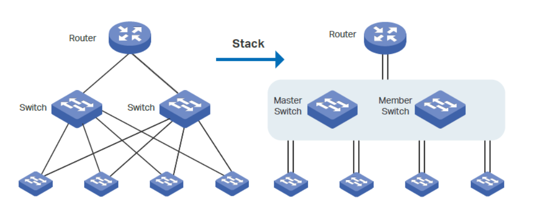
Create a Stack Group
1. Launch the controller and access a site.
2. Go to Devices > Device Group > Stack Group.
3. Click Create New Stack. Configure the parameters.

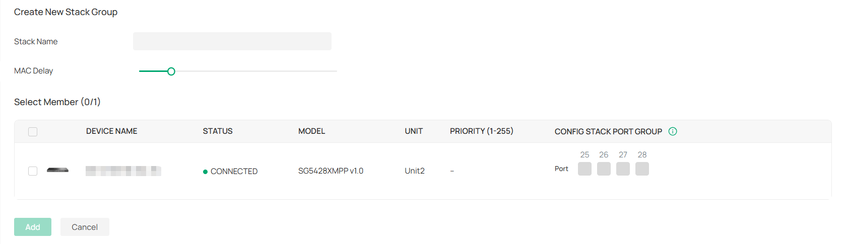
|
Stack Name |
Enter a name to identify the stack group. |
|---|---|
|
Select Member |
Select the switches to be stacked, and configure the following parameters: Unit: Specify the unit ID of the switch. Each switch in the stack has a unique unit ID for device management. Priority: Specify the stack priority of the switch. The higher the stack priority, the more likely the switch is to be elected as the Master Switch. A smaller value means a higher priority. Config Stack Port Group: Click the port to be stacked and choose the group ID. A port can join only one group. Note: To change the stacking mode of a port, please link down it first. After a port is switched to stacking mode, it can no longer be used as a service port. |
4. Apply the settings. Now you can connect the stack ports configured with the same group ID via Ethernet cables to stack the switches.
Note:
• Do not connect a stack port to a non-stack port. Otherwise, device operation may be affected.
• Connect stack ports only when they are set to the same group ID.
Configure and Monitor the Stack Group
The stack group logically virtualizes switches to one device as a whole. You can configure and monitor stack groups in a similar way as configuring and monitoring switches. For details, refer to Manage Switches via the Omada Controller.
Create and Manage Bridge Groups
Introduction to Bridge
Outdoor Bridge easily builds point-to-point and point-to-multi-point long range wireless connections. In practical application, it can help users to conveniently deploy APs over long range.
In a bridge system, the APs can be categorized mainly into two roles:
• Main AP
The Main AP connects to your gateway/router for network access. A bridge system generally has only one Main AP.
• Client AP
Client APs connect to the Main AP via wireless bridge. A bridge system may have one or several Client APs.

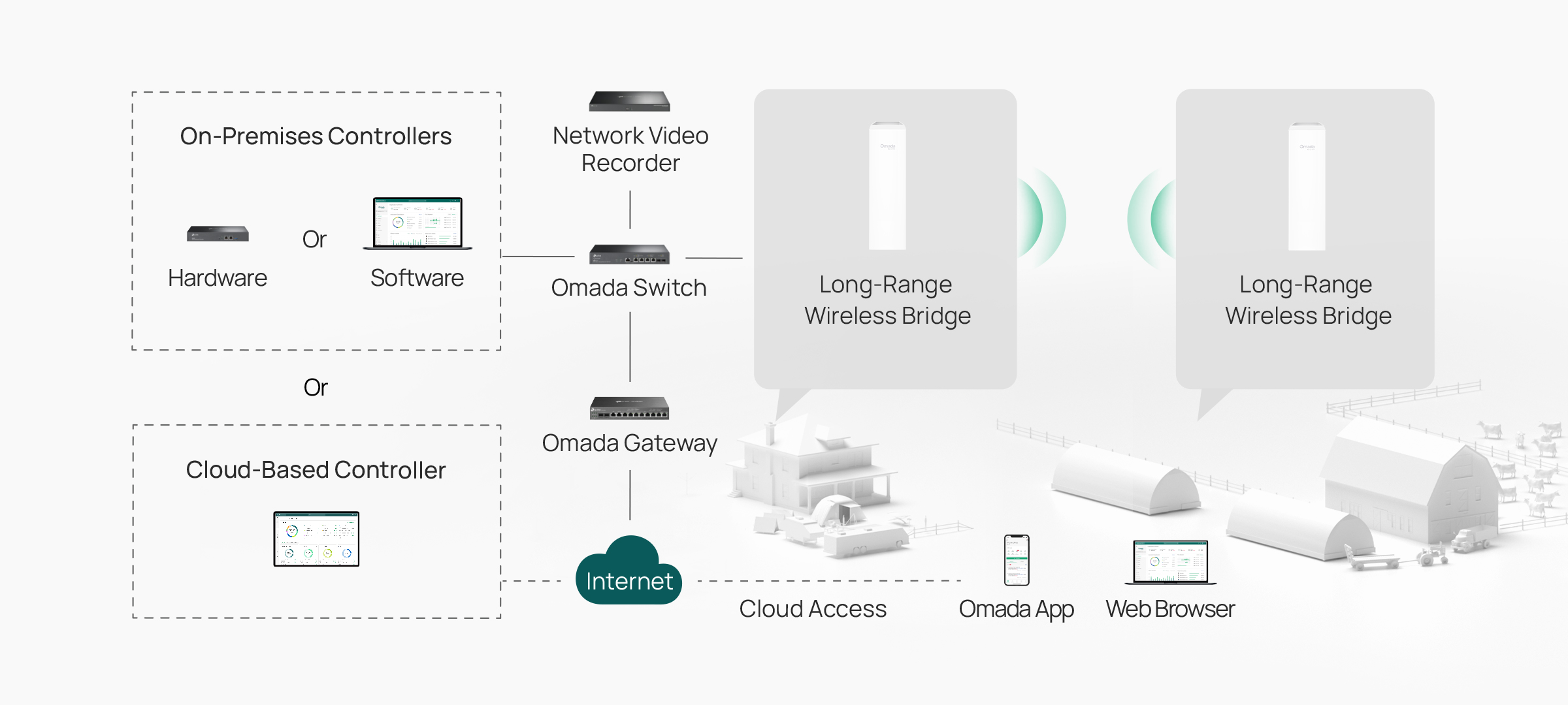
Create a Bridge Group
1. Obtain bridge APs and set up a bridge network by referring to the relevant AP Installation Guide.
2. Launch your controller and access a site.
3. Go to Devices > Device Group > Bridge Group. The controller will detect the bridge APs and show them in the Grouped list.

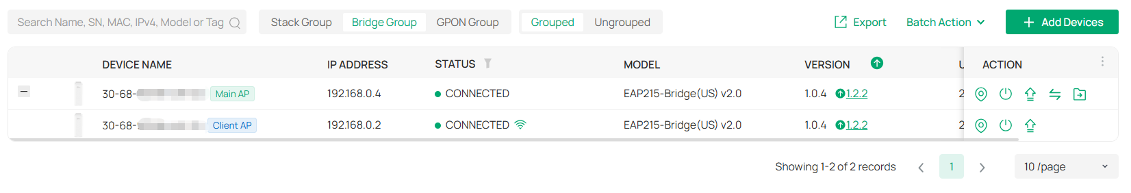
If you have ungrouped bridge APs, locate the AP in the Ungrouped list and click the Adopt icon to adopt it.

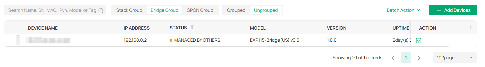
Configure and Monitor the Bridge Group
In the grouped bridge group list, you can configure and monitor the APs in the group.
|
|
(For connected devices) Click this icon and the LEDs of the device will flash to indicate the device’s location. The LEDs will keep flashing for 10 minutes, or you can click the |
|---|---|
|
|
(For connected devices) Click to reboot the device. |
|
|
Click to upgrade the device’s firmware version. This icon appears when the device has a new firmware version. |
|
|
Displays the current running configuration. Operators or Administrators or local user group members with execution rights for this command. |
| (Only for the Main AP) Click to change the AP's role to a Client AP. |
|
| (Only for the Main AP) Click to move the APs in the current bridge group to another site. Note: Bridge APs only support the Move to Site function on the Bridge Group page. |
Click the AP in the bridge group, then you can configure and monitor it in a similar way as configuring and monitoring a common AP. For details, refer to Manage APs via the Omada Controller.
View the Configuration Result
The Configuration Result page displays abnormal configuration results for devices excluding the OLT. If a device's configuration is entirely successful, it will not be displayed.
Launch the controller and access a site, then go to Devices > Configuration Result.
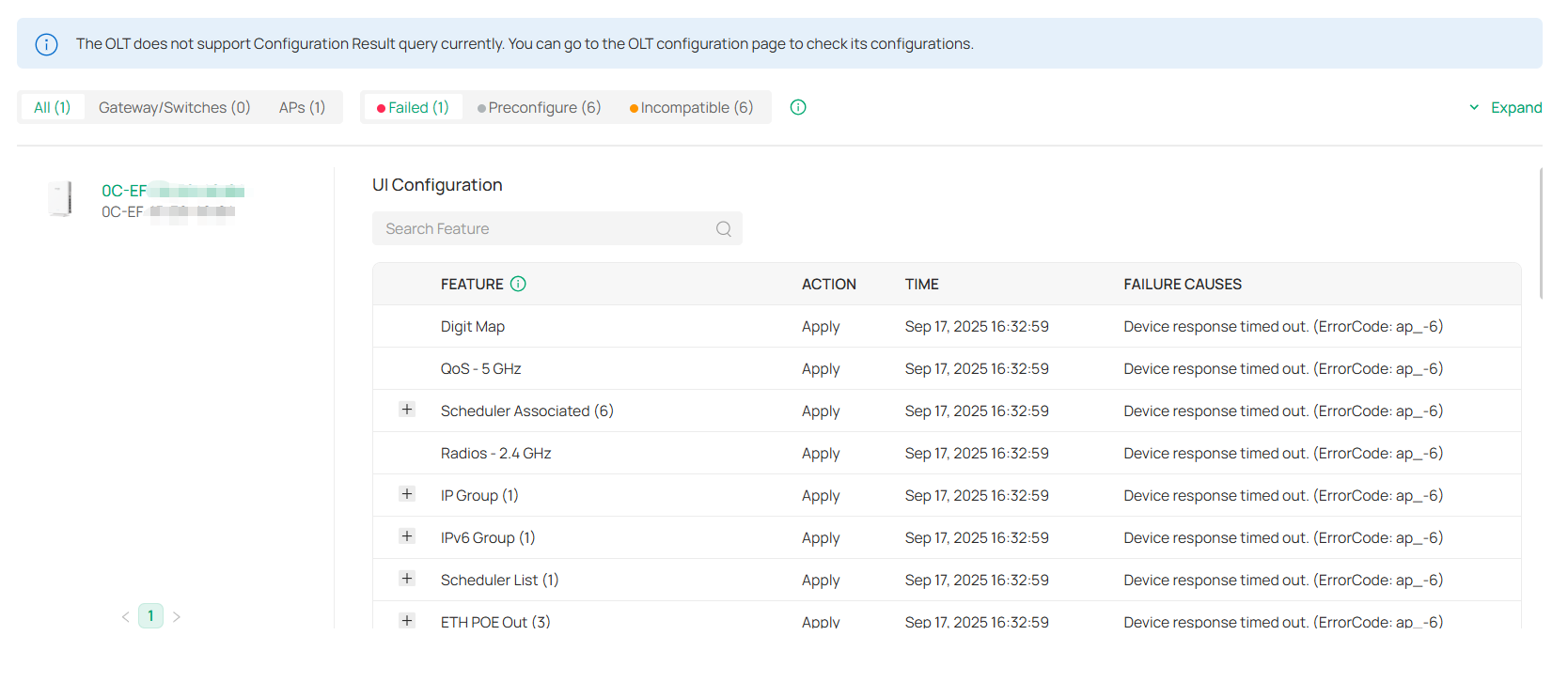

You can switch tabs based on the device type (All Devices, Gateway/Switches, and APs) or configuration result (Failed, Preconfigured, and Incompatible).
• Failed: The configuration is not delivered. For the failure cause of device response timeout, force provision the configuration or restart the device. For other failure causes, check the failed configuration, correct and save it, then deliver it to the device. If the problem still exists, contact our technical support.
• Preconfigured: The configuration may not be delivered because the device is offline. If your device is in connected state, force provision configuration or restart the device. If the problem still exists, contact our technical support. (This status does not affect the management and use of the device.)
• Incompatible: The configuration is not supported by the current device’s firmware.
You can click Expand on the right to search by Device Name and MAC Address.
Click on a device in the device list on the left to display its detailed configuration and failure causes.
Managing Clients
This chapter guides you on how to monitor and manage the clients using the Clients page and the Hotspot system.
Manage the Client List
The Clients page offers a straight-forward way to manage and monitor clients. It displays wired and wireless clients in the chosen site and their general information.
To manage clients, go to the Clients page in Site View.
You can manage clients in the client list. You can switch pages based on the client status (Online, Offline, Blocked, and All).

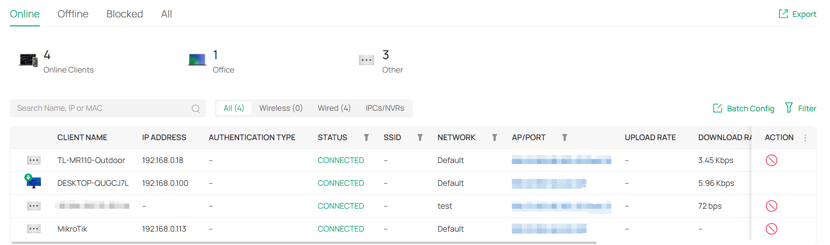
Monitor Connection Status
The Status column explains the connection status of clients.
|
PENDING |
The client has not passed the authentication and it is not connected to the internet. |
|---|---|
|
AUTHORIZED |
The client has been authorized and is connected to the internet. |
|
CONNECTED |
The client is connected to internet via non-portal network. |
|
AUTHENTICATION-FREE |
The client does not need to be authorized and it is connected to the internet. |
|
DISCONNECTED BLOCKED |
The client is blocked. |
Customize the Column
To customize the columns, click the ellipsis icon next to Action and check the boxes of information type.
To change the list order, click the upside-down triangle icon next to the column head, which indicates the ascending or descending order.
When this icon 
![]() appears in the Wireless Connection column, it indicates the client is in the power-saving mode.
appears in the Wireless Connection column, it indicates the client is in the power-saving mode.
Filter the Clients
Use the search box and tab bar above the table to filter clients.
To search for clients, enter the text in the search box.
To filter clients, a tab bar is above the table to filter the clients by client type. You can also filter clients by their status, connected SSID, network, AP/port by clicking the filter icons in the table header.
Quick Operations
For quick operations on a single client, click the icons in the Action column. The available icons vary according to the client status and connection type.
|
|
Click to block the client in the chosen site. |
|
|
Click to forget the client in the chosen site. |
|
|
(With portal authentication enabled) Click to manually authorize the client that has not passed the portal authentication. |
|
|
(With portal authentication enabled) Click to unauthorize the client that has passed the portal authentication. |
|
|
(For wireless clients) Click to reconnect the wireless client to the wireless network. |


Batch Config
You can configure clients in batches. Click Batch Config, select clients, and click Done. Then you can configure settings for the selected clients in batch.
Manage a Client
To manage a client, go to the Clients page in Site View. In the client list, click a client, then you can monitor and manage it in the Properties window and Client Management window.
Properties Window
The Properties window displays the basic information of the client. You can click the edit icon to edit the client name and information.

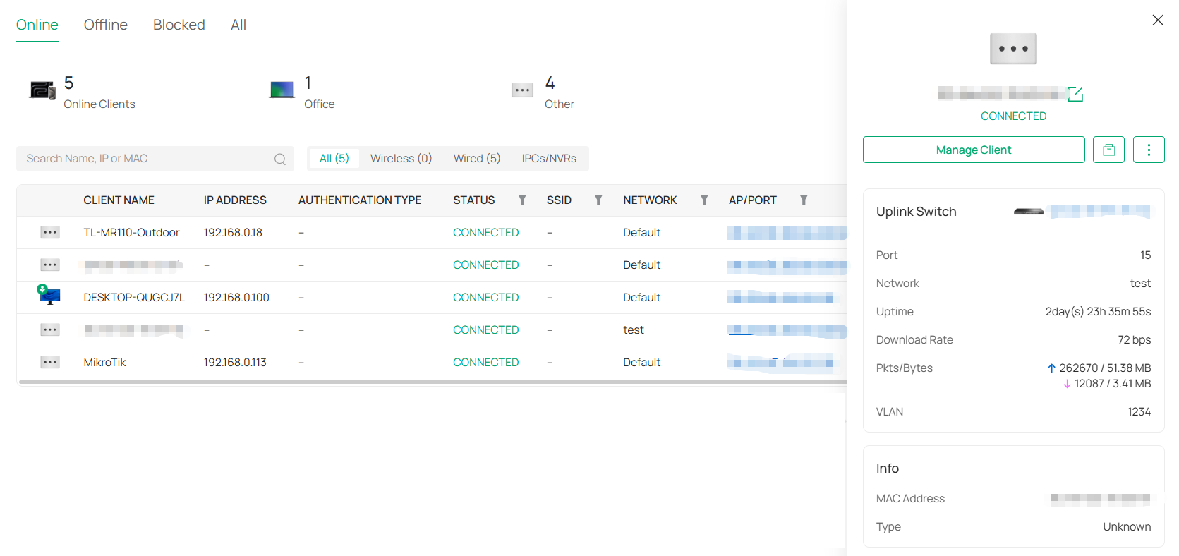
■ Quick Operations
Click the ![]()
![]() icon and choose an operation to quickly operate the client.
icon and choose an operation to quickly operate the client.
|
Block |
Click to block the client from accessing the site network. |
|---|---|
|
Forget |
Click to remove the client from the site network. Once forgotten, client settings will be wiped out. |
|
Reconnect |
(For wireless clients) Click to reconnect the wireless client to the wireless network. |
|
Authorize |
(With portal authentication enabled) Click to manually authorize the client that has not passed the portal authentication. |
|
IntelliRecover |
(Only for the client directly connected to the PoE switch) Click to enable the IntelliRecover function for the client so that it can be added to the IntelliRecover monitoring list. IntelliRecover can help you monitor the status of PoE devices, automatically repairing abnormal devices. |
■ Network Tools
Click the ![]()
![]() icon and choose a network tool to analyze the network.
icon and choose a network tool to analyze the network.
|
Network Check |
Test the network connectivity via ping or traceroute. |
|---|
Client Management Window
Click Manage Client to open the Client Management window to view more client details and change client settings.
In the management window, you can click + and select one or more clients to open new management windows, click the icon in the top left to minimize the windows to the icon in the right side, and click the icon to reopen the minimized windows.
You can also click each tab to monitor and manage the client.
■ Overview
In Overview, you can get an overview of the client, such as link status, online time, and more.

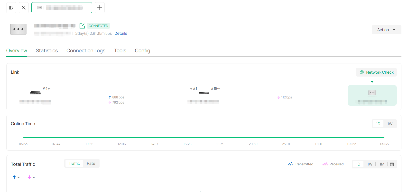
■ Statistics
In Statistics, you can check the DPI traffic statistics of the client.

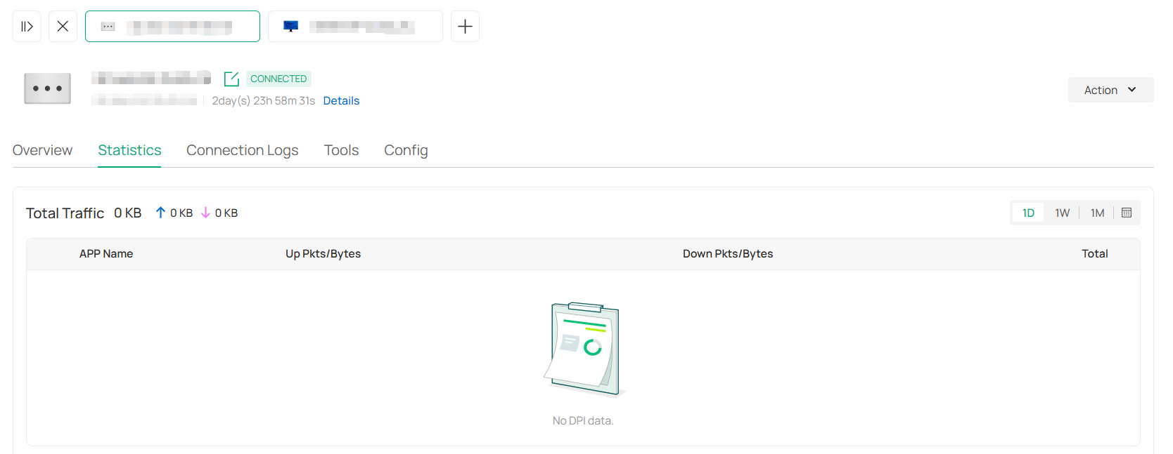
■ Connection Logs
In Connection Logs, you can check the connection logs of the client, such as association, roaming, disconnection, and more.

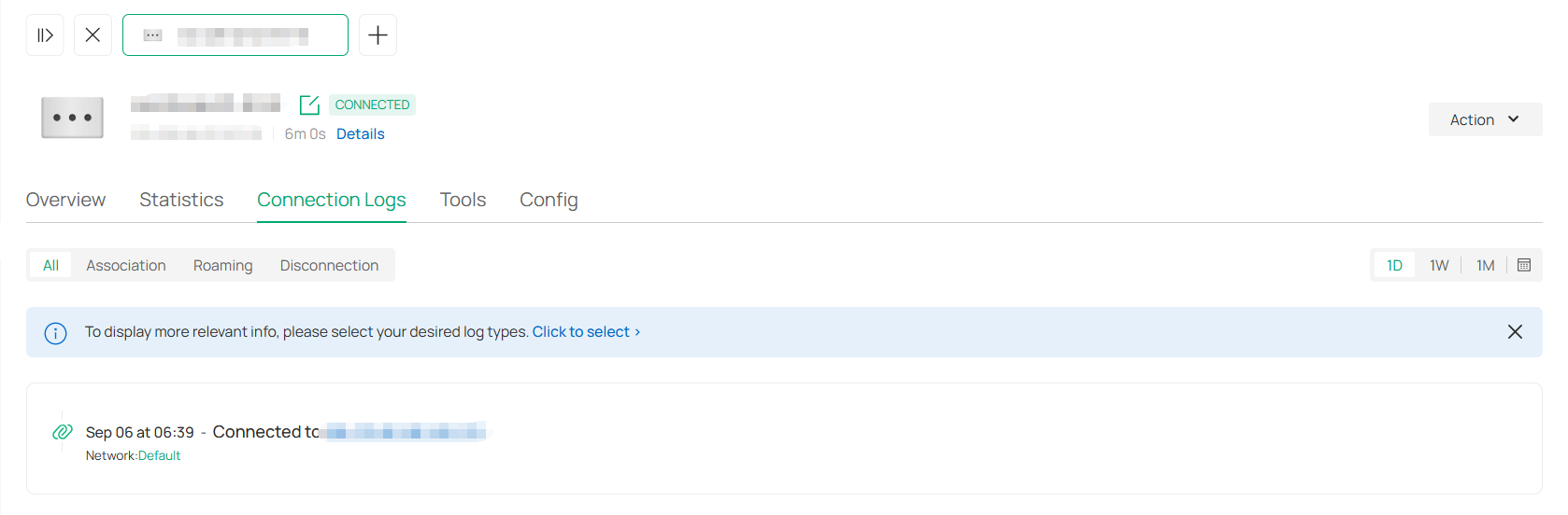
■ Tools
In Tools, you can use the network tool to test the network connectivity.

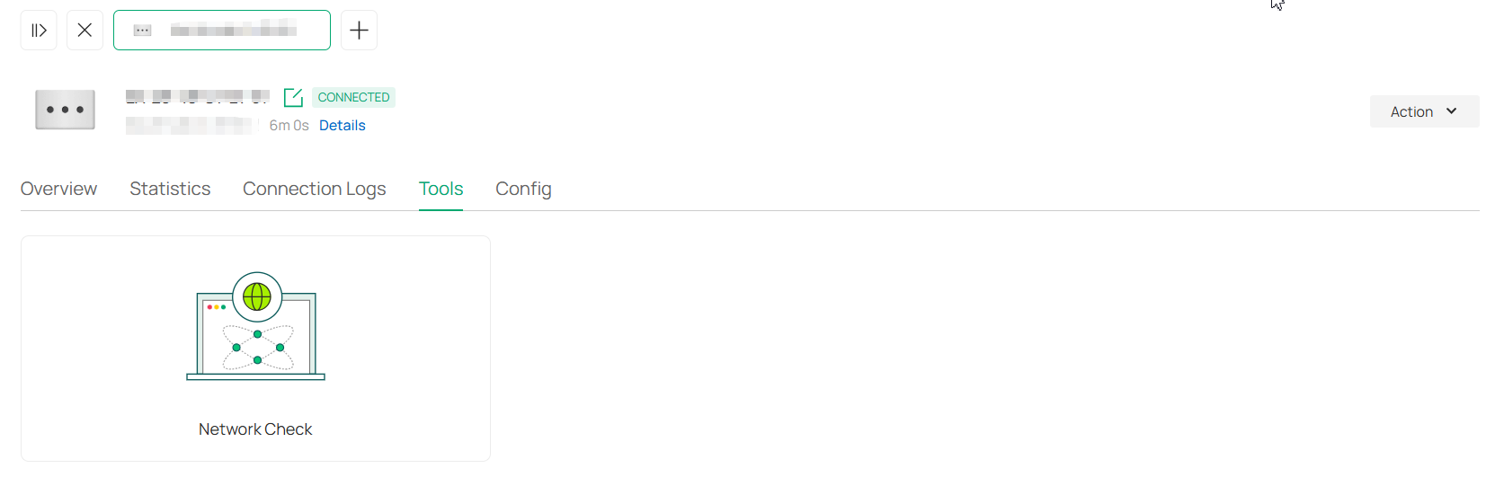
■ Config
In Config, you can edit client settings.

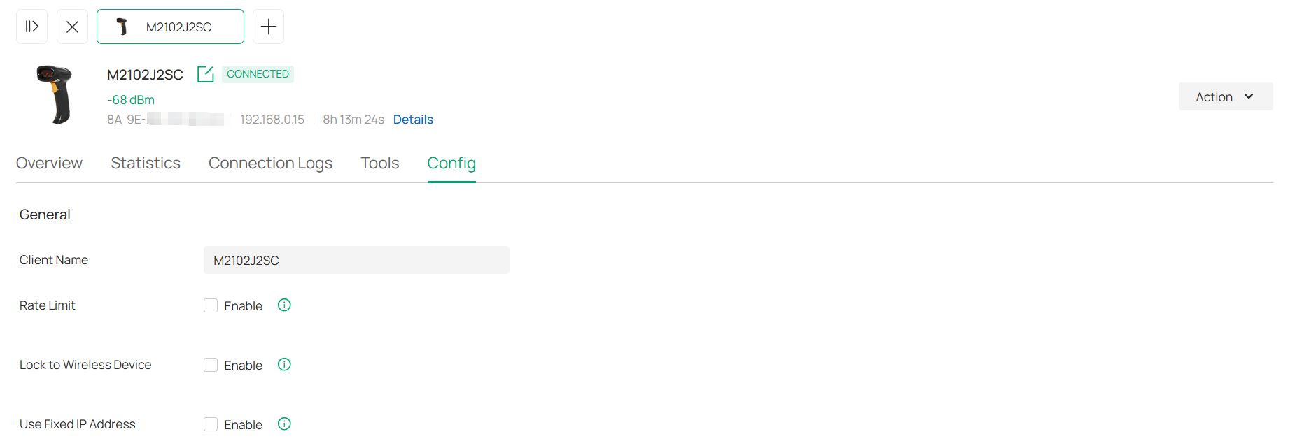
|
Client Name |
Specify the client’s name to better identify different clients, and the name is used as the client’s username in the table on the Clients page. |
|---|---|
|
Rate Limit |
Enable this function if you want to limit the download and upload rate of each client to balance bandwidth usage. When enabled, select an existing rate limit profile, create a new rate limit profile or customize the rate limit. Custom: Specify the Download Limit and Upload Limit based on needs. Note: Rate Limit on this page is only available for the clients connected to the EAPs. To limit the rate of the clients connected to the gateway or switch, go to the Bandwidth Control page. |
|
Lock to Wireless Device |
When enabled, you can lock the device to a specific wireless device for stable connection. To use this function, ensure your device is using the device MAC rather than a random MAC. Otherwise, the function may not take effect. Only 11ac and above products support this function. |
|
Use Fixed IP Address |
Click the checkbox to configure a fixed IP address for the client. With this function enabled, select a network and specify an IP address for the client. Note: A gateway is required for this function. Otherwise, you cannot set a fixed IP address for the client. |
Manage Client Authentication in Hotspot
Hotspot is a portal management system for centrally monitoring and managing the clients authorized by portal authentication. The following tabs are provided in the system for a easy and direct management.
|
Dashboard |
Monitor portal authorizations at a glance through different visualizations. |
|---|---|
|
Authorized Clients |
View the records of the connected and expired portal clients. |
|
Vouchers |
Create vouchers for Portal authentication, and view and manage the related information. |
|
Local Users |
Create local user accounts for Portal authentication, view their information, and manage them. |
|
Form Auth Data |
Customize your survey contents and publish it to collect data. |
|
Operators |
Create operator accounts for Hotspot management, view their information, and manage them. |
To access the system, click Hotspot in the sidebar of the Site interface.
Dashboard
In the Dashboard, you can monitor portal authorizations at a glance through different visualizations.
To open the dashboard, launch the controller and access a site, click Hotspot in the sidebar, then click Dashboard. Specify the time period to view portal authorization histories.

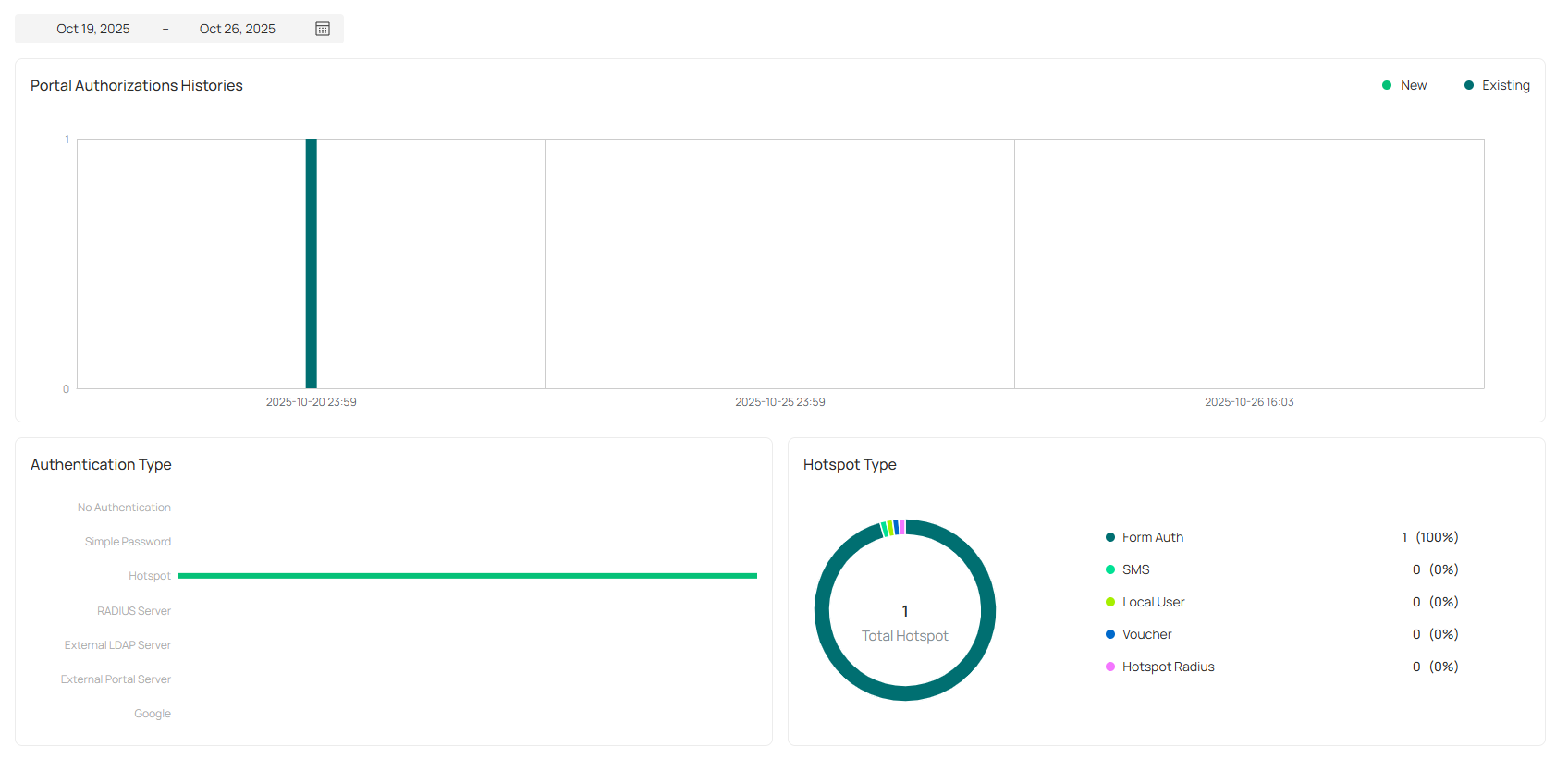
Authorized Clients
The Authorized Clients tab is used to view and manage the clients authorized by portal system, including the expired clients and the clients within the valid period.
To open the list of Authorized Clients, launch the controller and access a site, click Hotspot in the sidebar, then click Authorized Clients. You can search certain clients using the search box, view their detailed information in the table, and manage them using the action column.

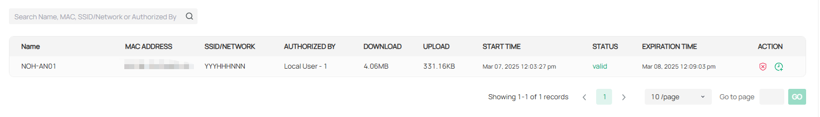
|
|
Click to extend the valid period of the authorized client. You can choose the preset time length or set a customized period based on needs. |
|
|
Click to disconnect the authorized client(s). If you disconnect an authorized client, the client needs to be re-authenticated for the next connection. |
|
|
Click to delete the expired client from the list. |


Vouchers
The Vouchers tab is used to create vouchers and manage unused voucher codes. With voucher configured and codes created, you can distribute the voucher codes generated by the controller to clients for them to access the network via portal authentication.
Follow the steps below to create vouchers for authentication:
1. Launch the controller and access a site, click Hotspot in the sidebar, then click Vouchers > Voucher Groups.
2. Click Create Vouchers Group on the upper-right.
3. Configure general voucher settings and click Save.

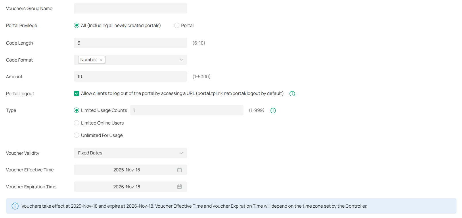
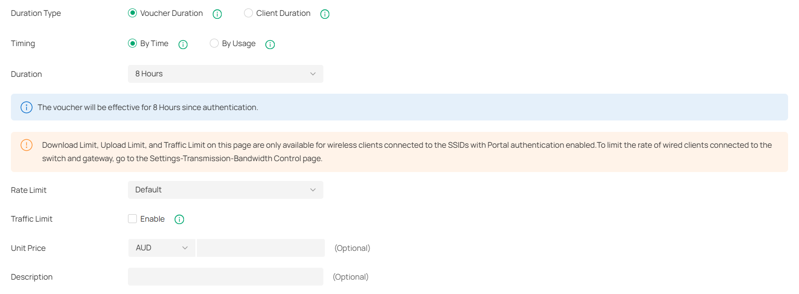
|
Vouchers Group Name |
Enter a name to identify the group. |
|---|---|
|
Portal Privilege |
All: The vouchers will take effect for all voucher type portals, including newly created ones. Portal: Select the portal for which the vouchers will take effect. |
|
Code Length |
Specify the length of the code(s) from 6 to 10 digits. |
|
Code Format |
Choose whether the voucher code is generated by numbers, letters, or a mixture. |
|
Amount |
Specify the number of voucher codes you want to create. |
|
Portal Logout |
Check the box to allow guests to log out of the portal by accessing a URL (portal.tplink.net/portal/logout by default). You can change the default URL by editing portal.logout.domain in the omada.properties file. Note: Some devices may require firmware update to support Portal Logout. |
|
Type |
Select a type to limit the usage counts or the number of authorized users of a voucher code. Limited Usage Counts: The voucher code can only be used for a limited number of times within its valid period. Limited Online Users: The voucher code can be used for an unlimited number of times within its valid period, but only a limited number of wireless clients can access the network with this voucher code at the same time. Unlimited For Usage: The voucher code can be used for an unlimited number of times within its valid period. |
|
Voucher Validity |
Specify the validity of vouchers in the group: Permanent: Vouchers will be valid permanently. Fixed Dates: Vouchers will be valid during the start and end dates you specify. Scheduled: Vouchers will be valid according to the schedule you set. |
|
Duration Type |
Specify whether to limit the voucher duration or client duration. Voucher Duration: Configure the duration for the voucher. Clients can use the voucher for the specified time duration (e.g., 8 hours after the first use). After reaching the voucher duration, the voucher will expire whether used or not. Client Duration: Configure the duration for the client. The client can use vouchers for the specified time duration (e.g., 8 hours after the first use). After reaching the client duration, the client will expire and cannot use the vouchers to access the network. |
|
Timing |
By time: The voucher code takes effect within a fixed period of time after authentication. By Usage: The voucher code takes effect according to the actual time used by the client. |
|
Duration |
Select the valid period for the voucher code(s). |
|
Rate Limit |
Select an existing rate limit profile, create a new rate limit profile or customize the rate limit for the voucher codes. Custom: Specify the download/upload rate limit based on needs. Download/Upload Limit: Click the checkbox and specify the rate limit for download/upload for wireless clients using the voucher code(s). The value of the download and upload rate can be set in Kbps or Mbps. Note: Rate Limit on this page are only available for wireless clients connected to the SSIDs with Portal authentication enabled. To limit the rate of wired clients connected to the switch and gateway, go to Network Config >Transmission > Bandwidth Control. |
|
Traffic Limit |
Click the checkbox and specify the daily/weekly/monthly/total traffic limit for the voucher, and the value of the traffic limit can be set in MB or GB. Once the limited is reached, the client(s) can no longer access the network using the voucher. Note: Traffic Limit on this page are only available for wireless clients connected to the SSIDs with Portal authentication enabled. To limit the rate of wired clients connected to the switch and gateway, go to Network Config >Transmission > Bandwidth Control. |
|
Unit Price (Optional) |
Set the amount and currency type for the voucher (for statistical purposes only). |
|
Description (Optional) |
Enter notes for the created voucher code(s), and the input description is displayed in the voucher list under the voucher tab. |
4. Configure voucher pattern settings, preview it, then click Save.

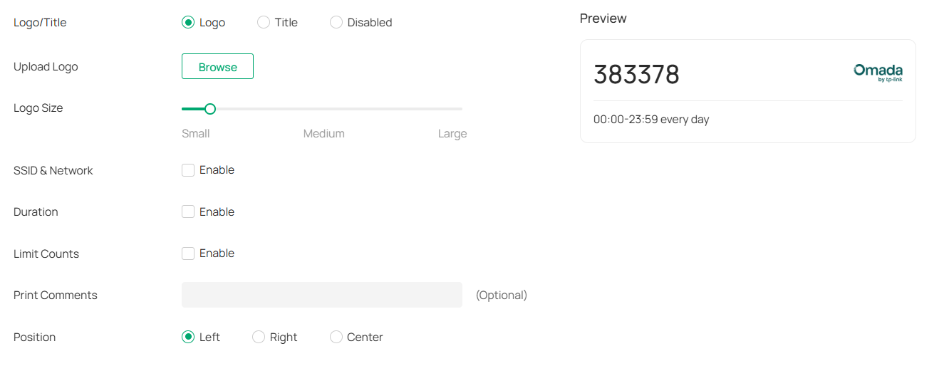
|
Logo/Title |
Choose whether to display a logo or title on the vouchers. Logo: Upload a logo and adjust its size to display the logo on the vouchers. Title: Enter a title and adjust its size to display the title on the vouchers. Disabled: No logo or title will be displayed on the vouchers. |
|---|---|
|
SSID & Network |
Enable this option and select the SSID or network to display if needed. |
|
Duration |
Enable this option to display the voucher validity duration if needed. |
|
Limit Counts |
Enable this option to display the voucher limit counts if needed. |
|
Print Comments |
Enter print comments if needed and the comments will be printed when you print the created voucher codes. |
|
Position |
Choose the position to display the voucher code. |
5. The voucher group is generated.

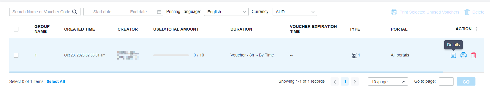
|
|
The voucher code can be used for an unlimited number of times within its valid period, but only a limited number of wireless clients can access the internet with this voucher code at the same time. The number on the right shows the limited number of users. |
|
|
The voucher code can only be used for a limited number of times within its valid period. The number on the right shows the limited number of authentication times. |


You can click the Details icon in the Action column to view the voucher codes. If you want to change the voucher pattern settings, click Edit Voucher.

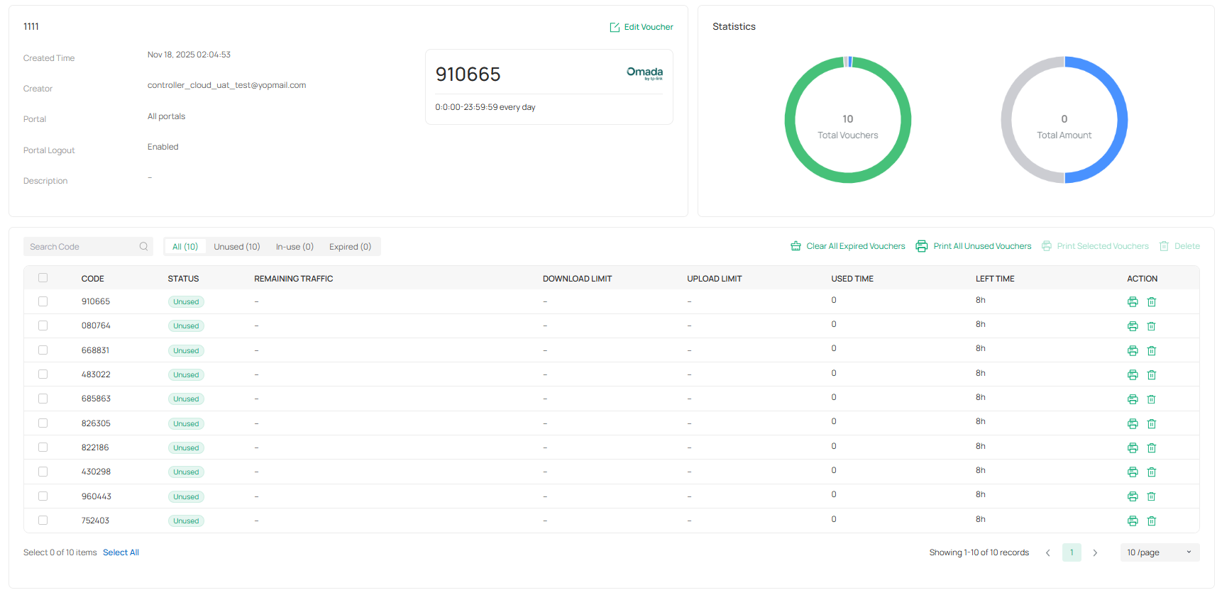
6. Print the vouchers. Click the print icon to print a single voucher, or click checkboxes of vouchers and click Print Selected Vouchers to print the selected vouchers. And you can click Print All Unused Vouchers to print all unused vouchers.

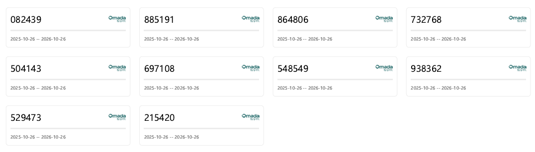
7. Distribute the vouchers to clients, and then they can use the codes to pass authentication. If a voucher code expires, it will be automatically removed from the list.
8. To delete certain vouchers manually, click the trash bin icon to delete a single voucher, or select multiple voucher codes and click Delete to delete them at a time.
9. On the Vouchers > Statistic page, you can view the historical statistical data of vouchers.

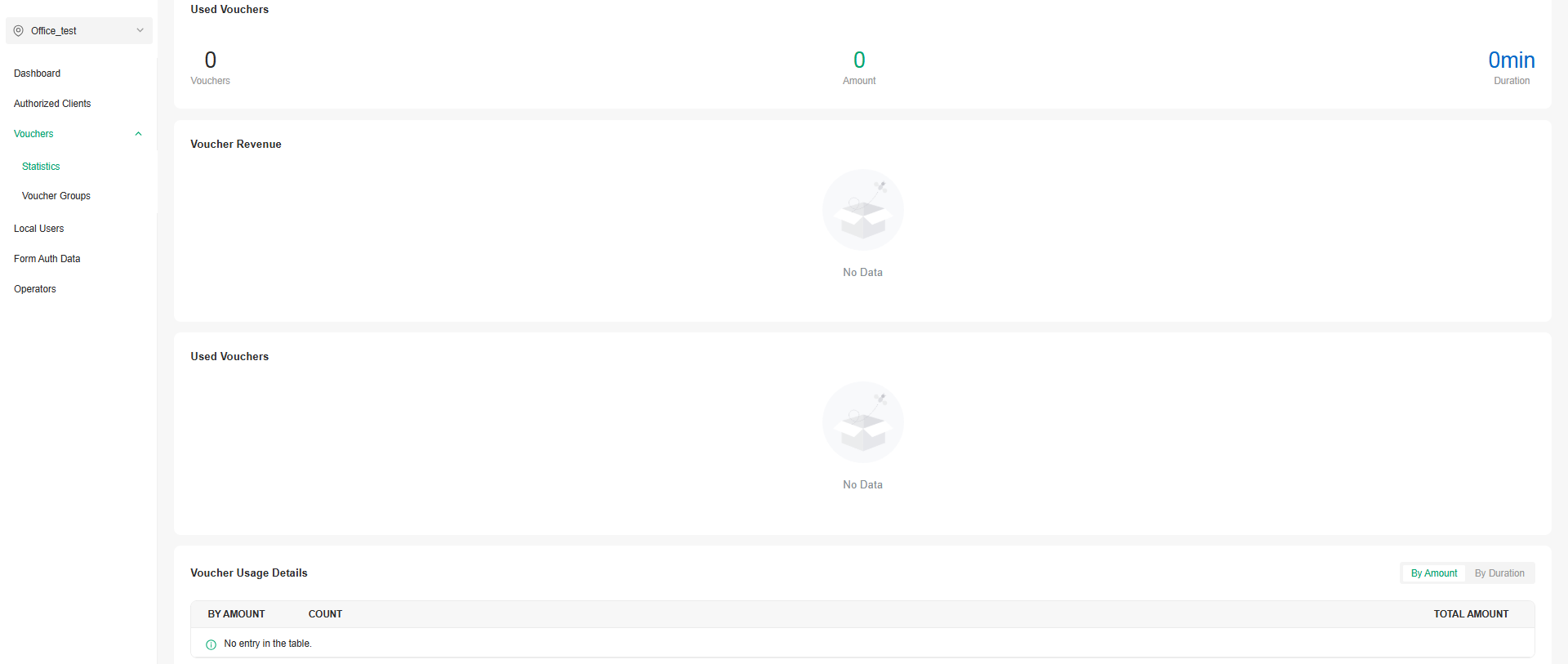
Local Users
The Local Users tab is used to create user accounts for authentication. With the Local User configured, clients are required to enter the username and password to pass the authentication. You can create multiple accounts and assign them to different users.
There are two ways to create local user accounts: create accounts on the page and import from a file.
To create local user accounts, follow the steps below.
1. Launch the controller and access a site, click Hotspot in the sidebar, then click Local Users.
2. Create Local User accounts through either of the following ways.
■ Create Local User accounts
Click Create User on the upper-right, and the following window pops up. Configure the following parameters and click Save.

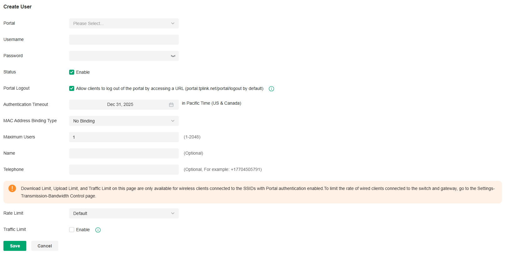
|
Portal |
Select the portal for which the local users will take effect. |
|---|---|
|
Username |
Specify the username. The username should be different from the existing ones, and it is not editable once it is created. |
|
Password |
Specify the password. Local users are required to enter the username and password to pass authentication and access the network. |
|
Status |
When the status is enabled, it means the user account is valid. You can disabled the user account, and enable it later when needed. |
|
Portal Logout |
Check the box to allow guests to log out of the portal by accessing a URL (portal.tplink.net/portal/logout by default). You can change the default URL by editing portal.logout.domain in the omada.properties file. Note: Some devices may require firmware update to support Portal Logout. |
|
Authentication Timeout |
Specify the authentication timeout for local users. After timeout, the users need to log in again on the authentication page to access the network. |
|
MAC Address Binding Type |
There are three types of MAC binding: No Binding, Static Binding and Dynamic Binding. No Binding: No MAC address is bound to the local user account. Static Binding: Bind a MAC address to this user account manually. Then only the user with the this MAC address can use the username and password to pass the authentication. Dynamic Binding: The MAC address of the first user that passes the authentication will be bound to this account. Then only this user can use the username and password to pass the authentication. |
|
Maximum Users |
Specify the maximum number of users that can use this account to pass the authentication. |
|
Name (optional) |
Specify a name for identification. |
|
Telephone (optional) |
Specify a telephone number for identification. |
|
Rate Limit |
Select an existing rate limit profile, create a new rate limit profile or customize the rate limit for the local users. Custom: Specify the Download Limit and Upload Limit based on needs. |
|
Traffic Limit |
Click the checkbox and specify the daily/weekly/monthly/total traffic limit for the local user account, and the value of the traffic limit can be set in MB or GB. Once the limited is reached, the user(s) can no longer access the network using this account. Note: Traffic Limit on this page are only available for wireless clients connected to the SSIDs with Portal authentication enabled. To limit the rate of wired clients connected to the switch and gateway, go to the Network Config > Transmission > Bandwidth Control. |
■ Create Local User accounts from files
Click Import Users on the upper-right, and the following window pops up. Select a file in the format of CVS or Excel, and click Import. To see required parameters and corresponding explanation, refer to Create Local User accounts. Note that the imported file will override the current user data.

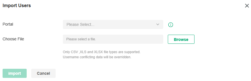
|
Portal |
Select the portal to which the local users will be imported. |
|---|
3.The local user account(s) will be created and displayed in the module. You can view the information of the created local users, search certain accounts through the name, and use icons for management.

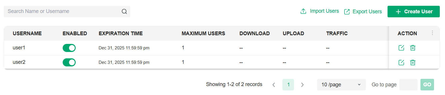
|
Import Users |
Click to add local user(s) from files in the format of CVS or Excel. It is recommended when you need to create local users in batches. Select the portals based on needs, and the local users will be imported to the chosen portal. Note that the imported file will override the current user data. |
|---|---|
|
Export Users |
Click to export the local user(s) to files in the format of CVS or Excel. Select the portals based on needs, and the local users of the chosen portal will be exported. |
Form Auth Data
The Form Auth Data tab is used to create and manage surveys. You can customize your survey contents and publish it to collect data.
To create surveys, follow the steps below.
1. Launch the controller and access a site, click Hotspot in the sidebar, then click Form Auth Data.
2. Click Create New Survey and the following window pops up.

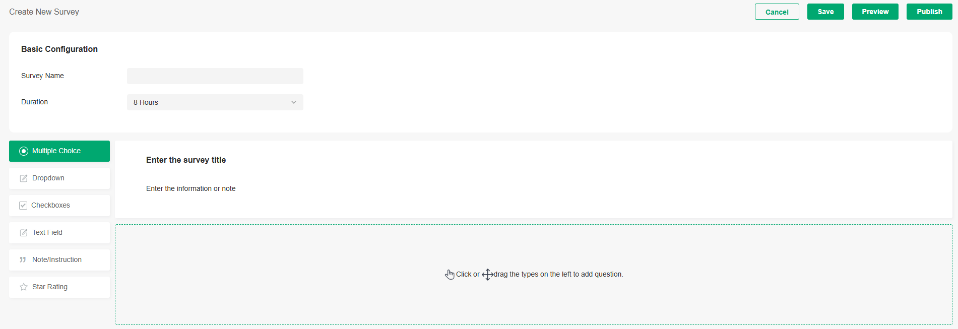
3. Specify the survey name and duration, then customize the contents.
4. Preview and save the settings or publish the survey.
5. The surveys are created and displayed in the table. You can use icons for management and click the ellipse icon for more management options.


Operators
The Operators tab is used to manage and create operator accounts that can only be used to remotely log in to the Hotspot system and manage vouchers and local users for specified sites. The operators have no privileges to create operator accounts, which offers convenience and ensures security for client authentication.
To create operator accounts, follow the steps below.
1. Launch the controller and access a site, click Hotspot in the sidebar, then click Operators.
2. Click Create Operator on the lower-left, and the following window pops up.

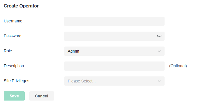
3. Specify the username, password, and role for the operator account. Admin role has read and write permissions, while Viewer role has read-only permissions.
4. (Optional) Enter a description for identification.
5. Select sites from the drop-down list of Site Privileges. Click Save.
6. The operator accounts are created and displayed in the table. You can view the information of the create operator accounts on the page, search certain accounts through the name and notes, and use icons for management.


7. Then you can use an operator account to log in to the Hotspot system:
■ For software controller
Visit the URL https://Controller Host's IP Address:8043/ControllerID/login/#hotspot (for example: https://192.168.0.174:8043/4d4ede7983bb983545d017c628feaa3d/login/#hotspot), and use the operator account to enter the Hotspot system.
■ For hardware controller
Visit the URL https://Controller Host's IP Address:443/ControllerID/login/#hotspot (for example: https://192.168.0.174:443/4d4ede7983bb983545d017c628feaa3d/login/#hotspot), and use the operator account to enter the Hotspot system.
■ For cloud-based controller
Visit the URL https://URL of the controller/ControllerID/login/#hotspot, and use the operator account to enter the Hotspot system.
Managing Accounts
This chapter gives an introduction to different user levels of controller accounts and guides you on how to create and manage them.
Introduction to User Accounts
The Controller offers multiple levels of access available for users: Owner, Super Admin, Admin, and Viewer. You can also create new account roles and customize their permissions to access different features.
Since the controller can be accessed both locally and via cloud access, users can be further grouped into local users and cloud users.
Multi-level administrative account presents a hierarchy of permissions for different levels of access to the controller as required. This approach ensures security and gives convenience for management.
Moreover, in the user accounts list of the Owner/Super Admin, all accounts it created will be displayed. The accounts created by each administrator will be hidden by default, making the interface more systematic and to the point.
■ Owner
The Owner has access to all features.
The account who first launches the controller will be the Owner (used to be recognized as Main Admin in earlier controller versions). It cannot be changed and deleted.
■ Super Admin
The Super Admin can manage all the other roles (except Owner) and the privileges of most features.
■ Admin
Admins have no permission to some modules, mainly including cloud access, migration, auto-backup and global view logs. They have read-only permission to some modules, such as global view license management and custom account roles.
Admins can be created and deleted by the Owner/Super Admin and Admins.
■ Viewer
Viewers can view the status and settings of the network, and change the settings in Hotspot Manager.
The entrance to Account page is hidden for viewers, and they can be created or deleted by the administrators.
■ Custom roles
Custom roles can be configured to access different features.
They can be created or deleted only by the Owner/Super Admin.
Note:
Please upgrade Omada APP to version 4.6 or later, otherwise you may not be able to log in with the accounts bound with customized roles.
Create and Manage Roles
1. Launch the controller and access the Global View.
2. Go to Accounts > Role. The Controller offers four levels of default roles: Owner, Super Admin, Admin, and Viewer.
3. If you want to create a custom role, click Add New Role.
4. Specify the role type name and customize the permissions for the role. Click Create.
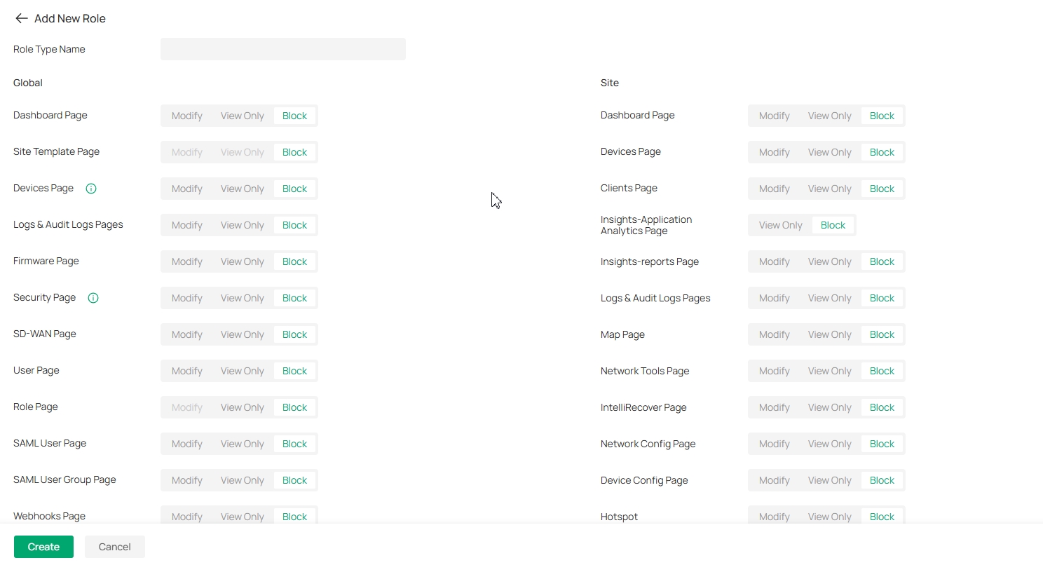
5. The new role will be displayed in the role list.
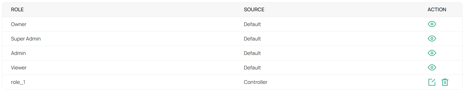
If you want to edit/delete a custom role, click the Edit/Delete icon in the ACTION column.
Create and Manage Local User Accounts
By default, the Controller automatically sets up a local user with the role called Owner as the primary administrator. The username and password of the Owner are the same as that of the controller account by default. The Owner cannot be deleted, and it can create, edit, and delete other levels of user accounts.
Edit the Owner Account
To view basic information and edit the Owner account, follow these steps:
1. Launch the controller and access the Global View.
2. Go to Accounts > User.
3. Click the Edit icon in the ACTION column and enter your current password to view or change your account.
4. Check and edit the account information. Click Save.
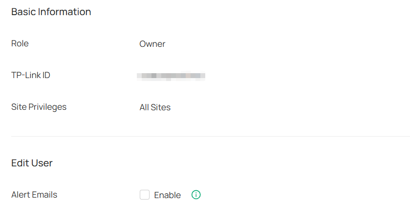
|
Alert Emails |
Check the box if you want the current user to receive emails about alerts of the privileged sites. |
|---|
Create and Manage Other Local Accounts
To create and manage a local user account, follow these steps:
1. Launch the controller and access the Global View.
2. Go to Accounts > User. Click Add New User.
3. Select Local User for the administrator type. Specify the parameters and click Create.

|
Valid Period |
Set the validity period of the user. Permanent: The user account will have permissions permanently unless modified or deleted. Temporary: The user account will have permissions only in the period you set. |
|---|---|
|
Username |
Specify the username. The username should be different from the existing ones. |
|
Password |
Specify the password. |
|
Role |
Select a role for the created user account. Super Admin: This role can manage all the other roles (except Owner) and the privileges of most features. Admin: This role has permissions to adopt and/or manage devices of the sites chosen in the site privileges, edit itself, create/edit/delete viewer accounts in its privileged sites. However, it cannot delete itself or edit/delete Owner/Super Admin. Viewer: This role can view the information of the sites chosen in the site privileges. It can only edit itself. Custom roles: If you have created custom roles, they will be displayed in the list. To create custom roles, refer to 16. 2 Create and Manage Roles. |
|
Site Privileges |
Assign the site permissions to the created local user. All sites (including newly created sites): The created user has device permissions in all sites, including all new-created sites. Specific sites: The created user has device permission in the sites that are selected. Select the sites by checking the box before them. |
|
Email (optional) |
Enter an email address for receiving alert emails. |
|
Alert/Event Emails |
Check the box if you want the created user to receive emails about alerts and events of the privileged sites. |
Create and Manage Cloud User Accounts
A Cloud-Based Controller enables cloud access by default and automatically sets up the cloud Owner. An on-premise controllers automatically sets up the cloud Owner if you have enabled cloud access and bound the controller account with a TP-Link ID in the quick setup. The username and password is the same as that of the TP-Link ID. The cloud Owner is cannot be deleted, and it can create, edit, and delete other levels of user accounts.
Set Up the Cloud Owner Account
For an on-premise controller, if you have not enabled the cloud access and bound the controller with a TP-Link ID in quick setup, you can follow the steps below to set up the cloud Owner:
1. Launch the controller and access the Global View.
2. Go to Settings > Cloud Access to enable Cloud Access and bind your TP-Link ID.

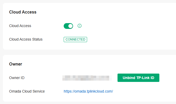
3. Go to Accounts > User. A cloud Owner with the same username as the TP-Link ID will be automatically created. The Cloud Owner cannot be deleted. You can log in with the cloud Owner when the cloud access is enabled.
Create and Manage Other Cloud Accounts
To create and manage cloud user account, follow these steps:
1. Launch the controller and access the Global View.
2. Go to Accounts > User. Click Add New User.
3. Select Cloud User for the administrator type. Specify the parameters and click Invite.
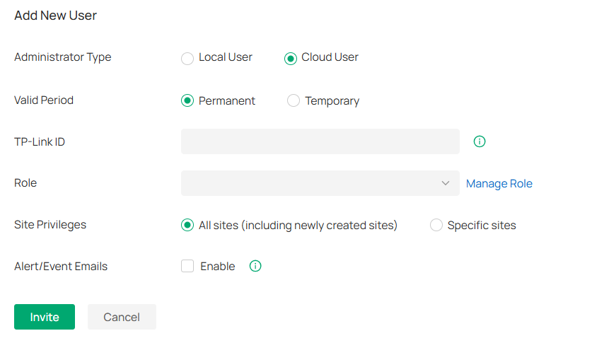
|
Valid Period |
Set the validity period of the user. Permanent: The user account will have permissions permanently unless modified or deleted. Temporary: The user account will have permissions only in the period you set. |
|---|---|
|
TP-Link ID |
Enter an email address of the created cloud user, and then an invitation email will be sent to the email address. If the email address has already been registered as a TP-Link ID, it will become a valid cloud user after accepting the invitation. If the email address has not been registered, it will receive an invitation email for registration. After finishing registration, it will automatically becomes a valid cloud user. |
|
Role |
Select a role for the created cloud user. Super Admin: This role can manage all the other roles (except Owner) and the privileges of most features. Admin: This role has permissions to adopt and/or manage devices of the sites chosen in the site privileges, edit itself, create/edit/delete viewer accounts in its privileged sites. However, it cannot delete itself or edit/delete Owner/Super Admin and other Admin accounts. Viewer: This role can view the information of the sites chosen in the site privileges. It can only edit itself. Custom roles: If you have created custom roles, they will be displayed in the list. To create custom roles, refer to 16. 2 Create and Manage Roles. |
|
Site Privileges |
Assign the site permissions to the created local user. All sites (including newly created sites): The created user has device permissions in all sites, including all new-created sites. Specific sites: The created user has device permission in the sites that are selected. Select the sites by checking the box before them. |
|
Alert/Event Emails |
Check the box if you want the created user to receive emails about alerts and events of the privileged sites. |
Manage User Accounts Across Controllers
Overview
If you have multiple controller, Account Manager allows you to centrally manage user accounts across controllers, assign users, enforce permissions, and streamline onboarding through Cloud Portal.
To use Account Manager, ensure your controllers meet the following requirements:
Controller Type: Omada On-Premises Networking Controllers only.
Version Required: v5.15.20 or later.
Status: Controllers must be online.
Cloud Access: Must be enabled.
Note:
• For MSP Controllers, permissions are applied at the MSP level.
• Account Manager currently supports Full Management (Super Admin) and View Only (Viewer) permissions.
Configuration
1. Launch a web browser and visit https://omada.tplinkcloud.com. Enter your TP-Link ID and password to log in. If you do not have a TP-Link ID, create a TP-Link ID first.
2. Go to Account Manager. The user accounts of all controllers managed by the current TP-Link ID will listed. The organization column displays the status of organization invitation: yellow text indicates that the user has been invited but not yet agreed, and gray text indicates that the user has agreed to join.
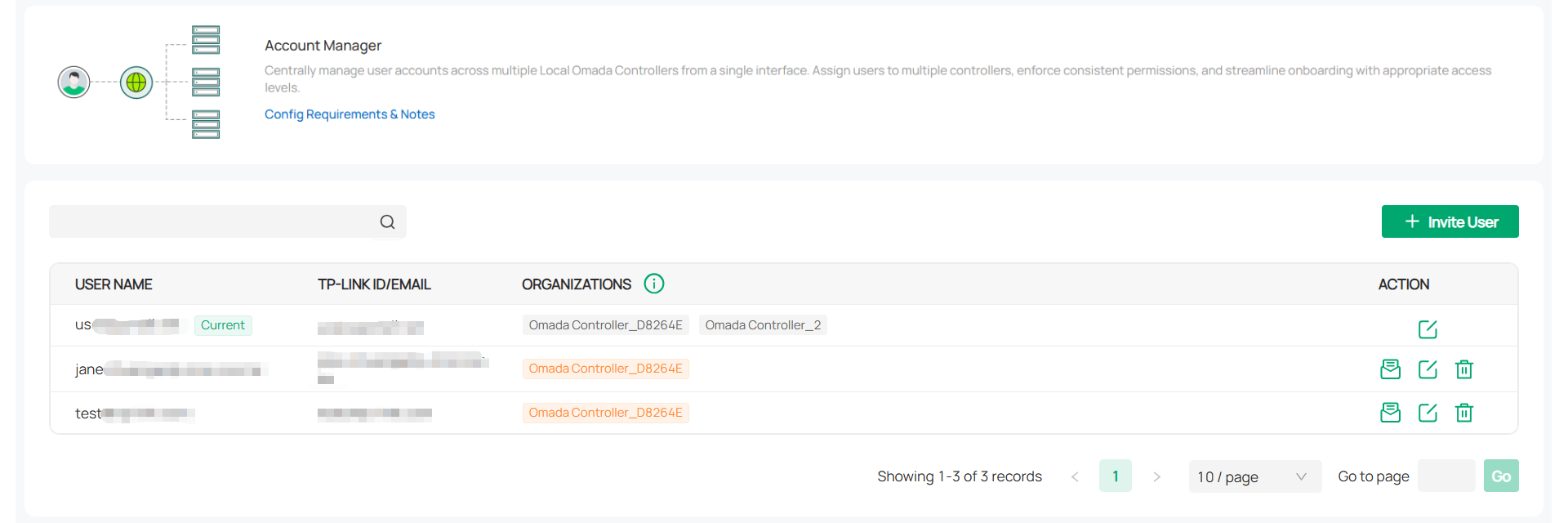
3. If you want to invite a user to help manage a controller organization, click Invite User and configure the parameters.
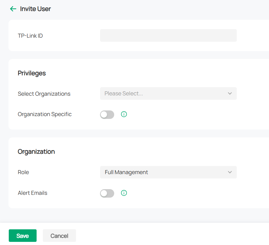
|
TP-Link ID |
Enter the TP-Link ID of the user you want to invite. If the email address has already been registered as a TP-Link ID, it will become a valid cloud user after accepting the invitation. If the email address has not been registered, it will receive an invitation email for registration. After finishing registration, it will automatically becomes a valid cloud user. |
|---|---|
|
Select Organizations |
Select one or multiple controller organization that the invited user can manage. |
|
Organization Specific |
Enable this option if you selected multiple controller organizations and want to configure the roles and alert settings for them separately. |
|
Role |
Set the permissions for the user: Full Management (Super Admin) or Viewer (View Only). |
|
Alert Emails |
With Alert Emails enabled, the organization will send the user emails about alerts. |
Monitoring and Maintaining the Network
This chapter guides you on how to monitor and maintain the network to ensure the stability and security of network operations.
Monitor the Network with Dashboard
Dashboard is designed for a quick real-time monitor of the site network. It is divided into four sections: Overview, Topology, Clients, and Traffic
Overview
The Overview page allows you to know your network status at a glance with visualized data charts, including ISP load status and pending alerts, network overview, top clients, top apps, internet and Wi-Fi activities, and AP density. You can specify the time period of data to display by using the time control in the upper right corner.
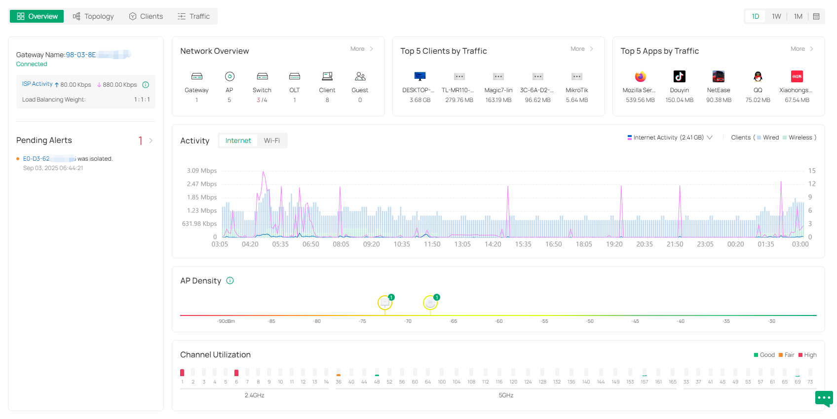
Topology
The Topology page displays the topology diagram. You can view the network devices and clients and check the network connections.
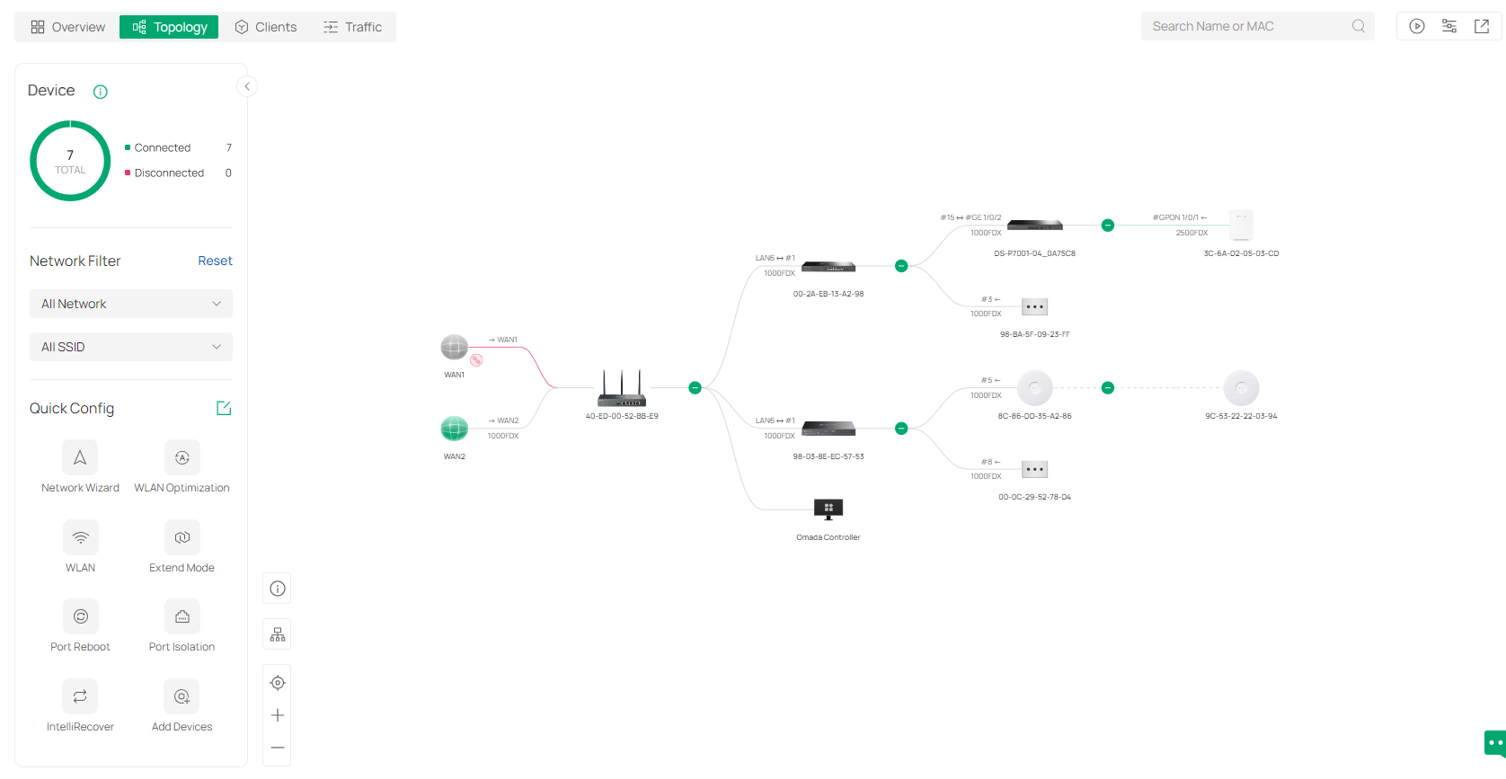
In the diagram, you can:
• Click the - icon to fold the branches.
• Click the icon of the client group to view clients connected to the same device.
• Hover the mouse over the device icon to view the device information.
• Click a device or client to open its Properties window for monitoring and management.
The control icons at the lower left corner of the diagram allow you to adjust the size of the topology, change the horizontal/vertical orientation of the topology, and view the legends.
The control icons in the upper right allow you to search for nodes in the map for quick locating, view the communication rate, filter the information/devices/terminals to display, and export the topology diagram. If the site does not have an Omada gateway, you can manually select the root node of a specific topology to correct the topology connectivity.
The left-side panel of the Topology page provides the device statistics chart, Network Filter, and Quick Config.
In Network Filter, you can filter the LAN and wireless network to display.
In Quick Config, you can click a configuration icon to quickly configure your network. To customize this section, you can click the edit icon and select the configuration icons to display.
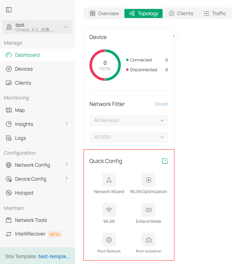
■ Network Wizard
In Network Wizard, you can quickly set up a guest wireless network with default settings or a custom network by manually setting network parameters.
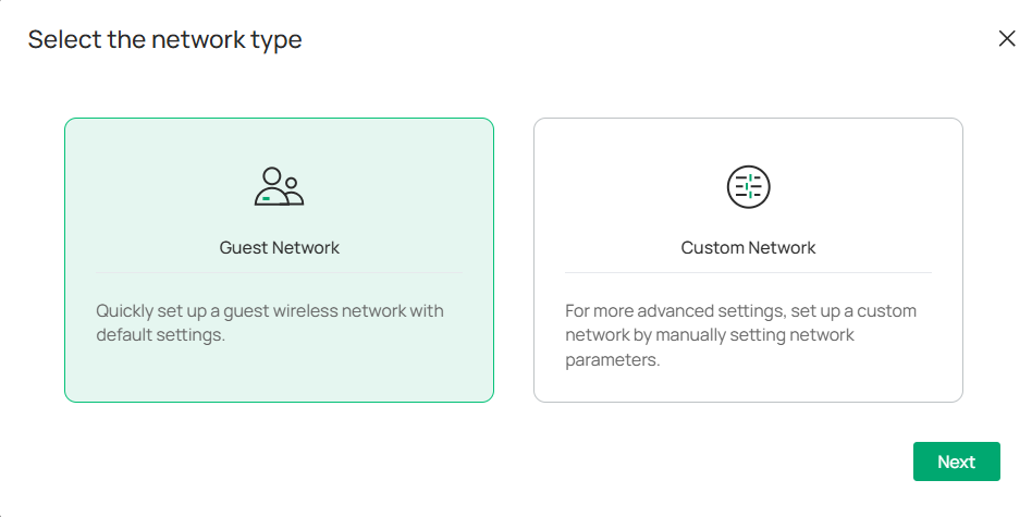
■ WLAN
In WLAN, you can quickly create an SSID and set up a basic wireless network.
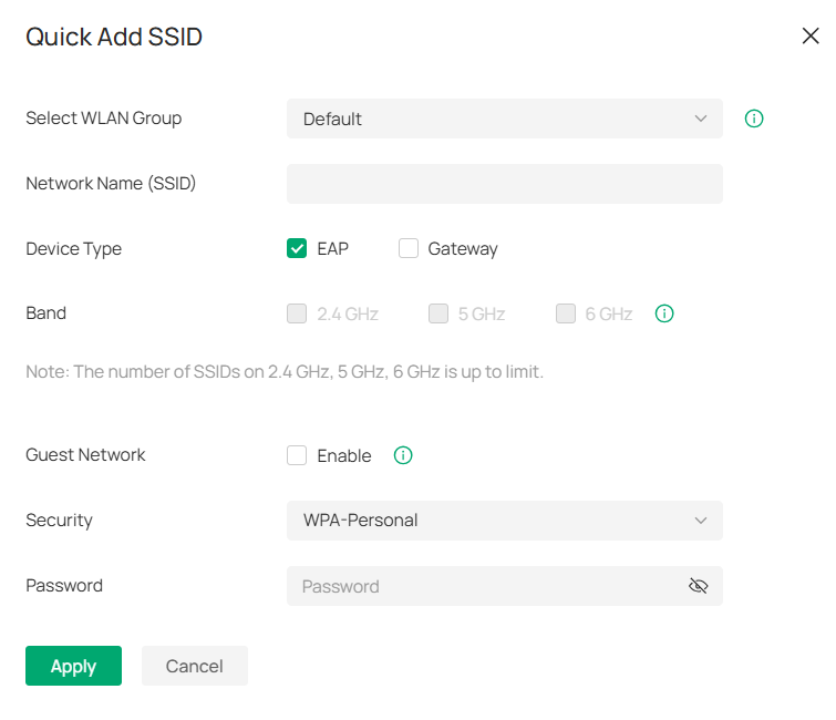
■ Extend Mode
In Extend Mode, you can quickly extend network cable transmission for switch ports. With this feature enabled, the Link Speed/Duplex will be downgraded to 10 Mbps/Auto and the Flow Control feature will be disabled.
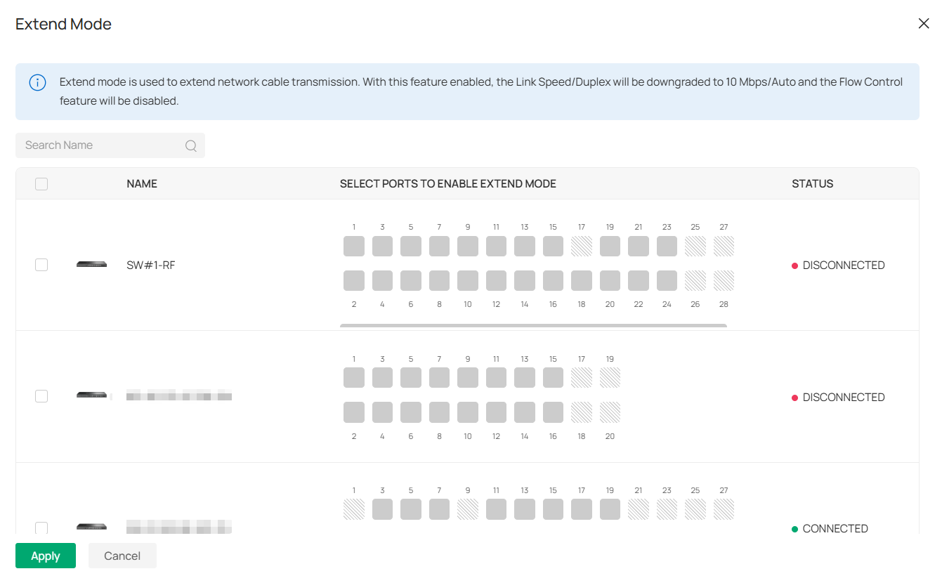
■ Port Reboot
In Port Reboot, you can quickly reboot the powered devices that are connected to the switch ports.
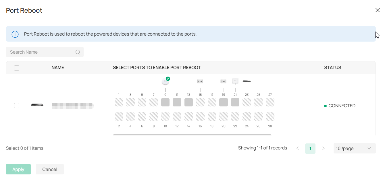
■ Port Isolation
In Port Isolation, you can quickly isolate the selected ports so that the ports cannot communicate with any other isolated port.
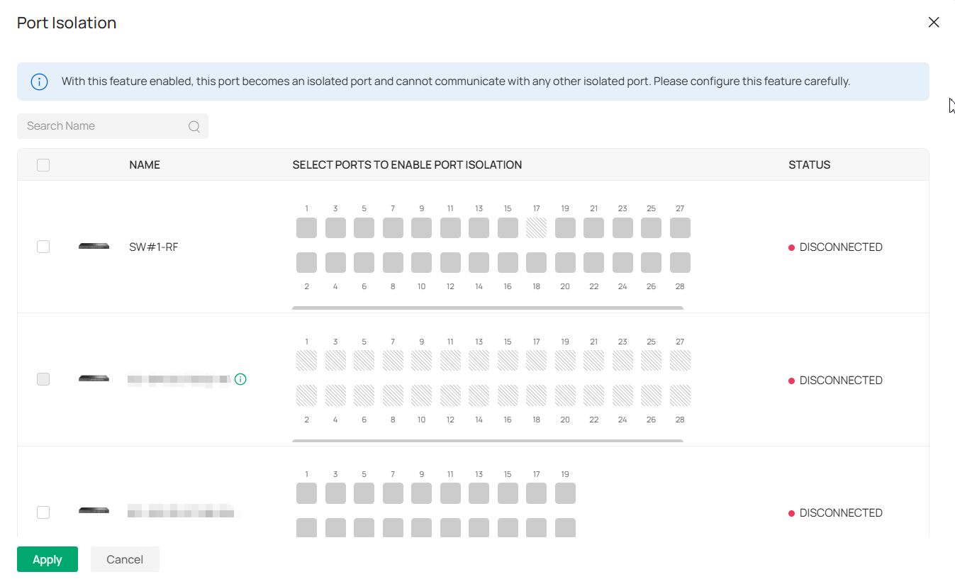
■ Others
Other Quick Config functions, including WLAN Optimization, VPN, ACL, Port Forwarding, Portal, and IntelliRecover, will guide you to the configuration page. Refer to the corresponding chapter in this manual for detailed guidance.
Clients
The Clients page displays visualized data charts of client information, including client quantity, distribution, top clients, and association activities.
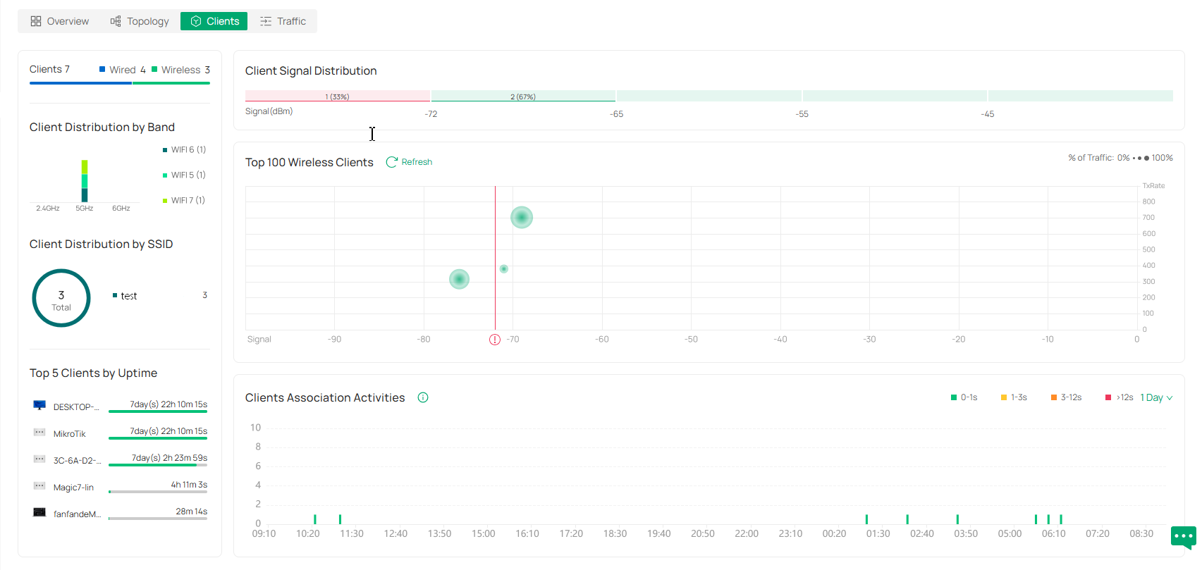
Traffic
The Traffic page displays visualized data charts of network traffic. You can click the tab to check the traffic statistics, top applications, and top clients. You can specify the time period of data to display by using the time control in the upper right corner.
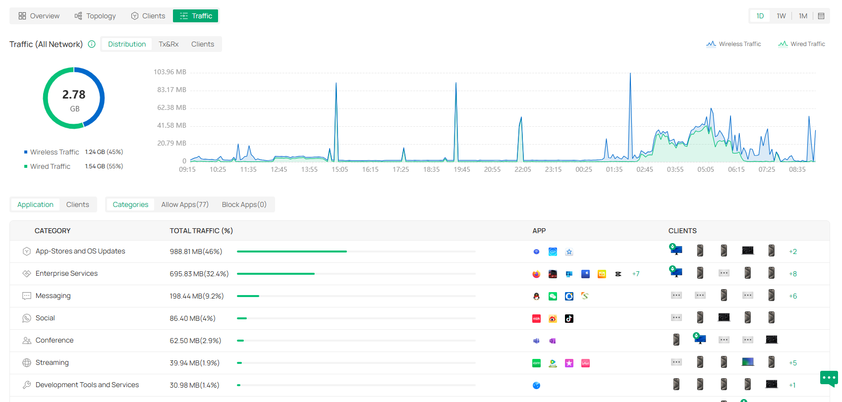
Monitor the Network with Map
With the Map function, you can customizes a visual representation of your network in Heat Map and visually display the geographic location of each device and site in Device Map and Site Map.
Heat Map
Go to Map > Heat Map, and a default map is shown as below. You can upload your local map images and add devices and different types of walls to customize a visual representation of your network.
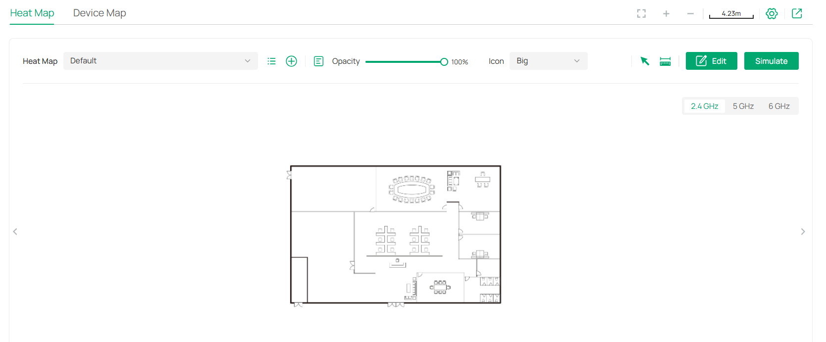
Click the following icons to add, edit, and select the map. After selecting a map, click and drag in the devices from the Devices list to place it on the map according to the actual locations.
|
|
Click to select a map from the drop-down list to place the devices. |
|
|
Click to edit maps in the pop-up window. Click the edit icon to edit the description and layout of the map. Click the delete icon to delete the map. |
|
|
Click to add a map. In the pop-up window, enter the description, select the layout, and upload an image in the .jpg, .jpeg, .gif, .png, .bmp, .tiff format. |
|
|
Adjust the opacity of the map. |
|
|
Click to select the icon size displayed on the map. |
|
|
Click to use the selection tool to select the elements including walls and devices on the map. |
|
|
Click to use the measurement tool. Draw a line on the map to measure the actual distance according to the map scale. |
|
|
Click to edit the elements including walls and devices on the map. |
|
|
Click to simulate the network heat map. Note: It is required to click Simulate to generate a new heat map after editing elements on the map. |
|
|
Click to fit the map to the web page. |
|
|
Click to zoom in the map. |
|
|
Click to zoom out the map. |
|
|
Click to set the map scale. Draw a line on the map by clicking and dragging, and then define the distance of the line. |
|
|
Click to set the default height of the added devices and the information displayed on the map. |
|
|
Click to export the network coverage report. |


Configuration
To generate a visual representation and heat map of your network, follow these steps:
1) Add a map and configure the general parameters for the map.
2) Add devices and walls, and configure the parameters.
3) View simulation results.
Step 1: Add Map
1. Go to Map > Heat Map and click 
![]() to add a new map. Then click Add.
to add a new map. Then click Add.
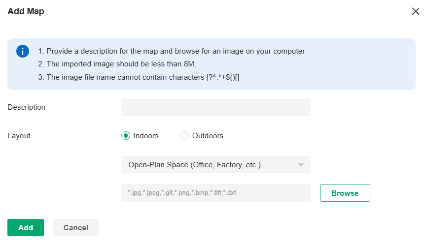
|
Description |
Enter a description for the map. |
|---|---|
|
Layout |
Select the general layout of the map, which will make the simulation more accurate and the upload the map in the .jpg, .jpeg, .gif, .png, .bmp, .tiff, .dxf format. Tip: You can upload a CAD (.dxf) file, and the controller will automatically identify the walls in the layout. |
2. Click the scale icon on the upper right to set a map scale. Draw a line on the map by clicking and dragging, and then define the distance of the line.
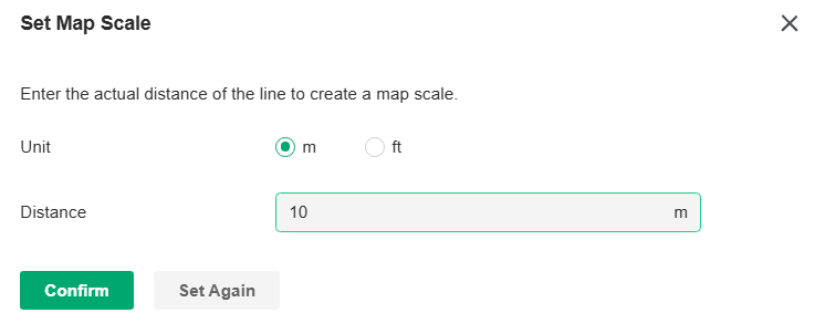
3. Click the settings icon to set the default height of the added devices and the information displayed on the map. Then click Confirm.
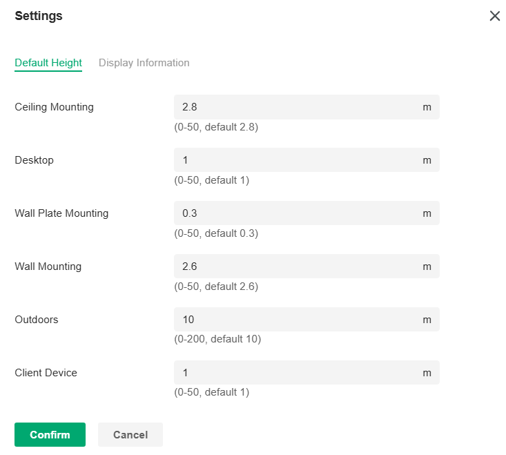

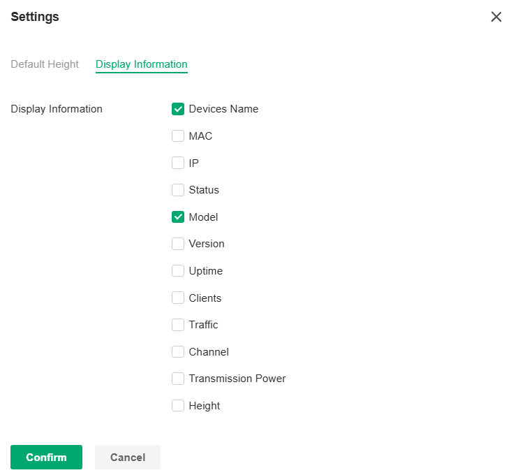
|
Default Height |
Specify the default height for devices. You can change the height for individual device later. |
|---|---|
|
Display Information |
Select the information you want to see on the map. |
Step 2: Add Devices and Walls
1. Click the Edit icon to enter the editing status of the map.
2. Click the Add Wireless Devices icon on the upper left, and the list of adopted devices and virtual devices will appear. Drag the devices to the desired place on the map.
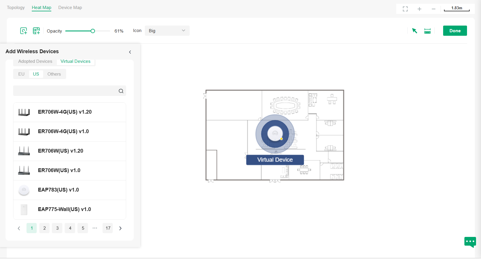
3. Click the Add Wall icon on the upper left. Select a type of wall/obstacle area and then start drawing on the map. Left click to start and right click / hit Enter to end.
You can also edit the details parameters of the walls and obstacles, delete, and add walls. Adding correct obstacles will increase the accuracy of simulation results.
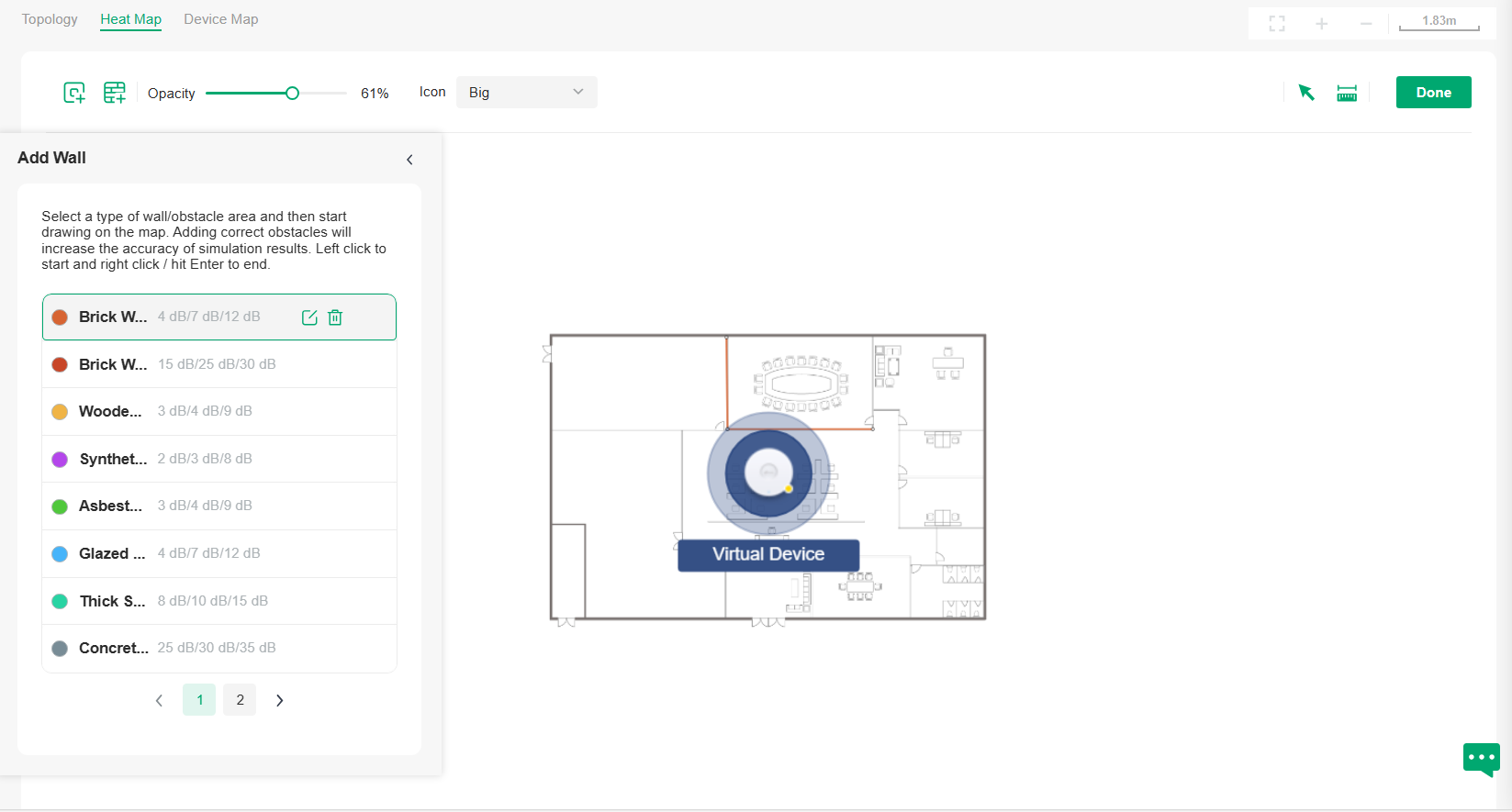
4. Click the Done icon to exit the editing status of the map.
Step 3: View and Export Results
Note:
It is required to click Simulate to generate a new heat map after editing elements on the map.
1. Click the Simulate icon to generate the heat map. You can adjust the receiver sensitivity, show signal strength, and view the simulation results according to your needs.
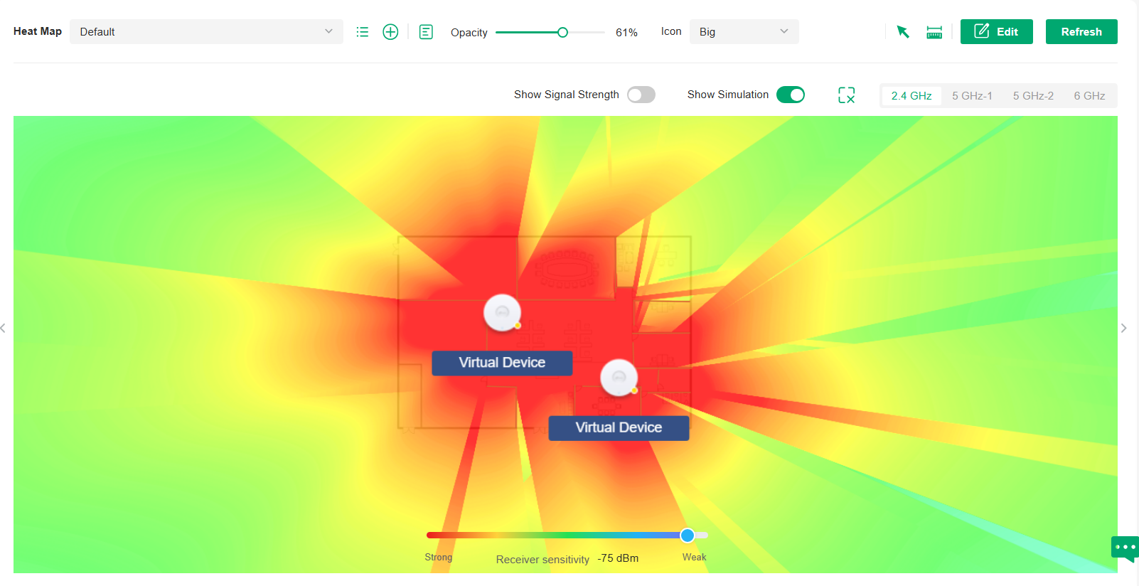
|
|
Enable the feature, and you can move the cursor to view the signal strength of a specific location. |
|
|
Enable or disable the display of simulation results on the map. |
|
|
Select 2.4GHz or 5GHz to view the simulation results of the band. |
|
|
Click and follow the instruction to specify an area to view the signal strength and the corresponding percentage. |
|
|
Adjust the receiver sensitivity, and the new settings will take effect after refreshing the simulation. |


2. (Optional) If you want to export a network coverage report, click the Export icon on the upper right to export a report in .docx format.
Device Map
Prerequisite
A valid Mapbox API Access Token is required to use the Device Map function.
Visit https://www.mapbox.com, register an account, and obtain the default token on the account page.

Configuration
1. Launch the controller and access a site. Go to Map > Device Map.
2. Click Bind API Access Token, enter the Mapbox API Access Token you obtained, then click Apply.
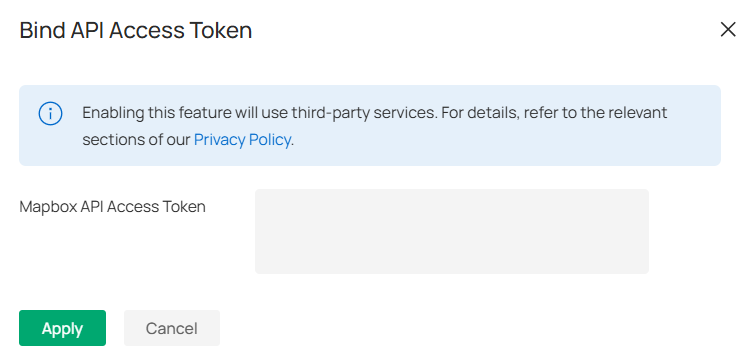
3. Use the map to manage your devices.
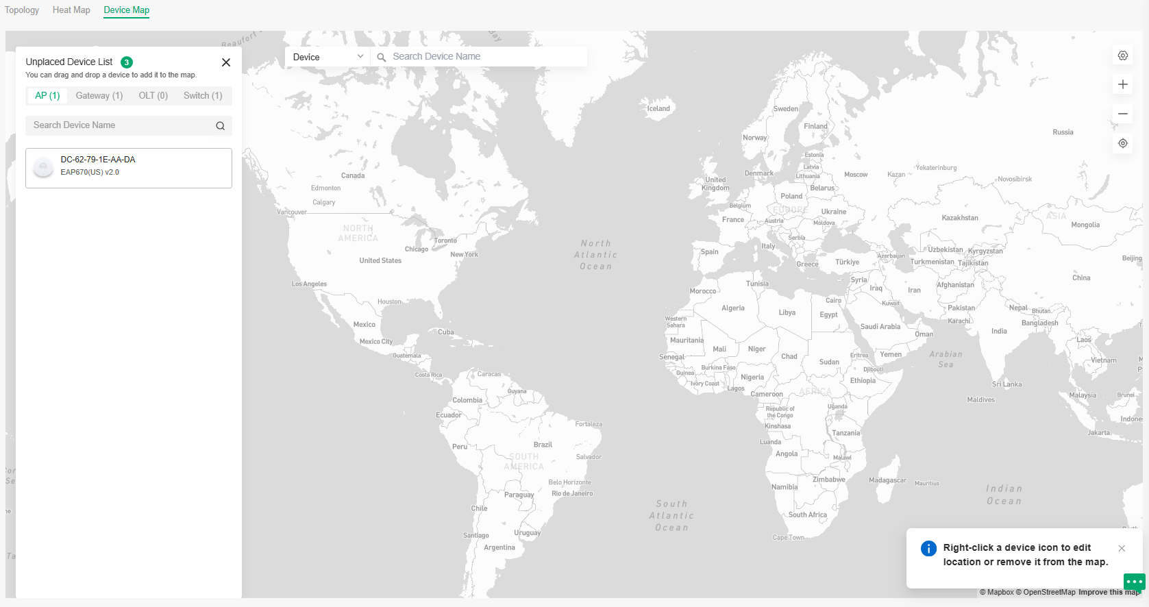
|
Unplaced Device List |
Display a list of sites that are not marked on the map. You can drag and drop a site to add it to the map. |
|---|---|
|
Search bar |
Select a catogary and enter the keyword to search for a site or address. |
|
|
Click to change or unbind the Mapbox API Access Token. |
|
|
Zoom in and zoom out the map. |
|
|
Locate to current location. |


Right-click a device icon to edit location or remove it from the map.

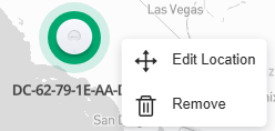
Click a device icon to view device info and edit settings.
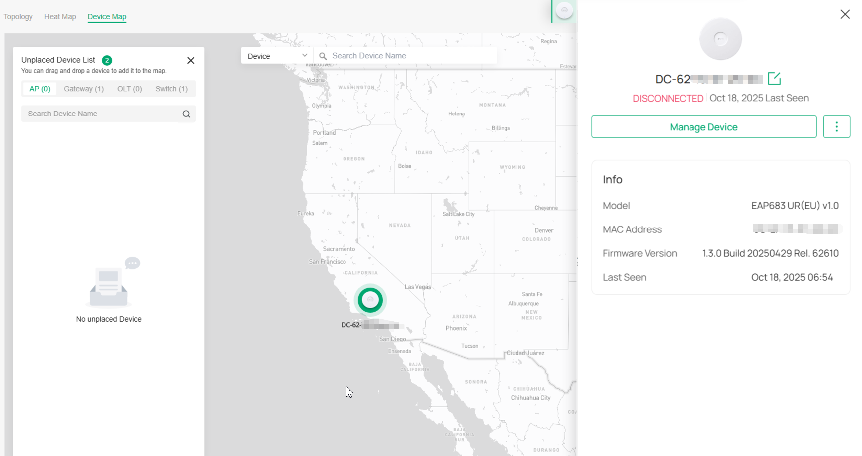
Site Map
Prerequisite
A valid Mapbox API Access Token is required to use the Site Map function.
Visit https://www.mapbox.com, register an account, and obtain the default token on the account page.
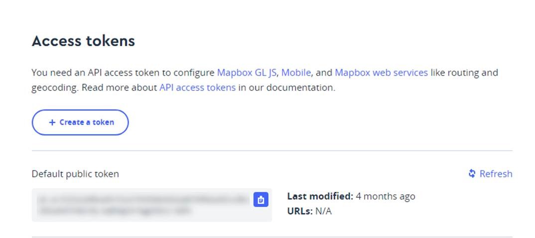
Configuration
1. Launch the controller and access the Global View. Go to Dashboard > Site Map.
2. Click Bind API Access Token, enter the Mapbox API Access Token you obtained, select the sites that can share the token, then click Apply.
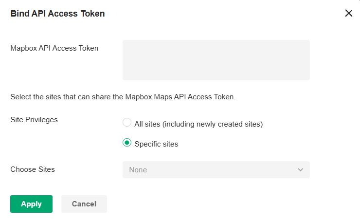
3. Use the map to manage your sites.
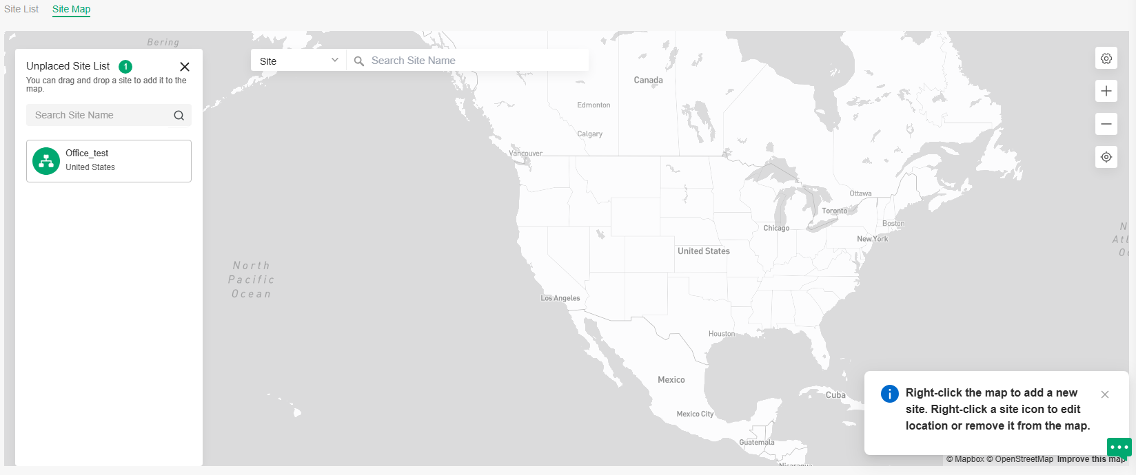
|
Unplaced Site List |
Display a list of sites that are not marked on the map. You can drag and drop a site to add it to the map. |
|---|---|
|
Search bar |
Select a catogary and enter the keyword to search for a site or address. |
|
|
Click to change or unbind the Mapbox API Access Token. |
|
|
Zoom in and zoom out the map. |
|
|
Locate to current location. |

Right-click the map to add a new site.

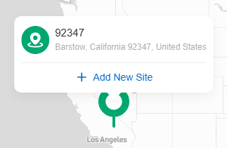
Right-click a site icon to edit location or remove it from the map.

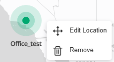
Click a site to view site info, and click Launch to access the site.
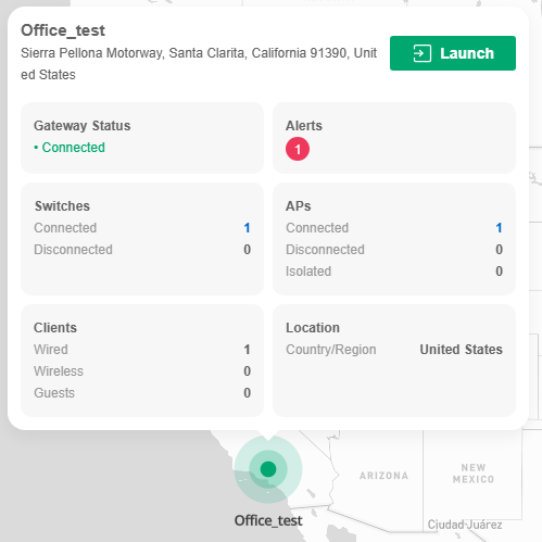

Monitor the Network with Insights
Reports
Network Report shows the statistics of various network indicators and their changes over time, helping network administrators to intuitively and comprehensively understand the current and historical operating status of their network. Thus, it facilitates network administrators to decide whether the controller and devices needs to be upgraded and optimized. It also provides network administrators and SI with data support for reporting network conditions.
In Site View, go to Insights > Reports, then you can view the connection data of the devices in the topology and the statistics of various network indicators and their changes over time.

Click the tabs on the top to view the statistics of specific section of the network.
|
Summary |
Display the statistics summary of the whole network. You can click the edit icon next to the tab name to customize the statistics to display. |
|---|---|
|
Wired |
Display the wired statistics of the whole network, including data related to gateway, switches, and wired traffic. You can click the edit icon next to the tab name to customize the statistics to display. |
|
Wireless |
Display the wireless statistics of the whole network, including data related to APs and wireless traffic. You can click the edit icon next to the tab name to customize the statistics to display. |
|
Client & Application |
Display the statistics of clients and applications in the network. You can click the edit icon next to the tab name to customize the statistics to display. |
Behind the tabs, you can click the + icon to add new tabs and click the setting icon to configure tab settings.
In the upper right, you can click the time control to specify the time period of data to display and click Export to save the network report.
Note:
For Linux system, please install Chromium before exporting the network report and make sure you can run Chromium as root.
Application Analytics
You can view detailed traffic information if you have adopted a gateway that supports DPI and enabled DPI in Application Control.
In Site View, go to Insights > Application Analytics, then you can monitor the network traffic at the application layer.
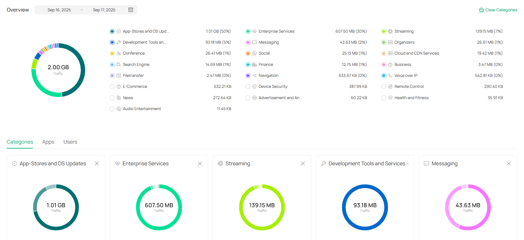
Monitor the Network with Logs
The controller uses logs to record the activities of the system, devices, users and administrators, which provides powerful supports to monitor operations and diagnose anomalies.
All logs can be classified from the following four aspects.
■ Occurred Hierarchies
Two categories in occurred hierarchies are Controller and Site, which indicate the log activities happened, respectively, at the controller level and in the certain site. Only Main Administrators can view the logs happened at the controller level.
■ Notifications
Two categories in notifications are Event and Alert, and you can classify the logs into them by yourself.
■ Severities
Four levels in alert severities are Critical, Error, Warning, and Info, whose influences are ranked from high to low.
■ Contents
Four types in contents are Operation, System, Device, and Client, which indicate the log contents relating to.
Manage Alerts
Alerts are the logs that need to be noticed and archived specially.
To configure logs as Alerts, click the Setting icon in the upper right and go to Alerts > Notifications Settings. All the logs configured as Alerts are listed under the Alerts tab for you to search, filter, and archive.
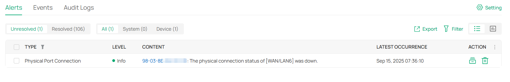
|
Export |
Click to export the logs in .CSV or .XLSX format. |
|---|---|
|
Filter |
Click the filter the logs to display. |
|
|
Click to change the view mode for a better overview.
|
|
|
Click the tab to filter the unresolved and resolved logs. You can click the Resolved icon or Batch Resolved to resolve a single log and all, respectively. |
|
|
Click All to display all types of logs. Click System or Deviceto display the corresponding type of logs only. |
|
Batch Resolved |
Click to resolve the logs in batches. |
|
Batch Delete |
Click to delete the logs in batches. |
|
|
Click to resolve the log entry. |
|
|
Click to delete the log entry. Once deleted the logs cannot be recovered. |


Manage Events
Events are the logs of state or activity changes within the system.
To configure logs as Events, click the Setting icon in the upper right and go to Events > Notifications Settings. All the logs configured as Events are listed under the Events tab for you to search and filter.
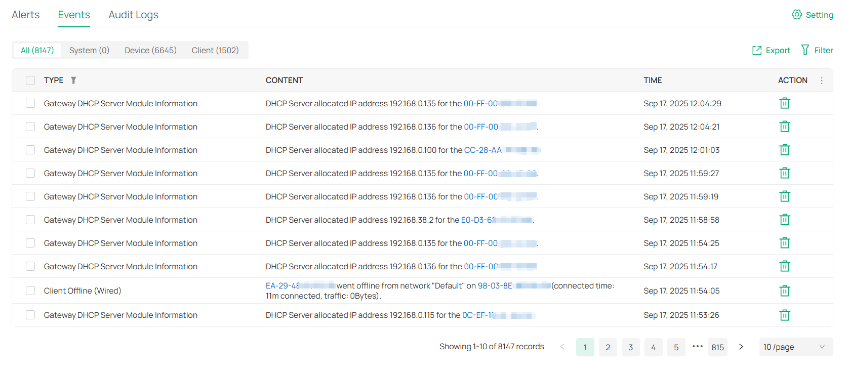
|
|
Filter the logs based on Start Time. Click the selector to open the calendar. Click a specific date twice in the calendar to display the logs on the day. To display the logs during a time range, click the start date and end date in the calendar. |
|---|---|
|
|
All/System/Device/Client: Click All to display all types of logs. Click System or Device or Client to display the corresponding type of logs only. |
|
Export |
Click to export the logs in .CSV or .XLSX format. |
|
Filter |
Click the filter the logs to display. |
|
Batch Delete |
Click to delete the logs in batches. |
|
|
Click to delete the corresponding event logs. |

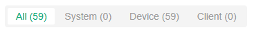

Manage Audit Logs
Audit log records information about which accounts have accessed the system or site, and what operations they have performed during a given period of time.
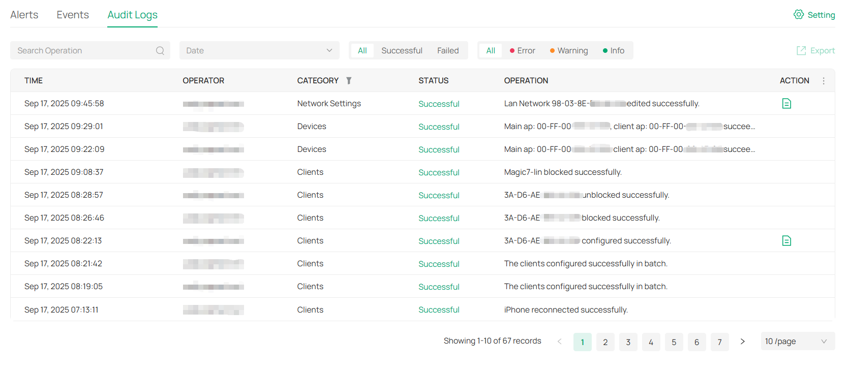
• If you want to export audit logs:
Check the boxes to select entries, click Export in the upper right corner, and specify the file type to download.
Configure Alert/Event Notifications
To configure alert/event notifications, follow the steps below:
Step 1: Enable Mail Server
Launch the controller and access the Global View. Go to Settings > Server Settings to enable Mail Server. For detailed configuration, refer to the section Mail Server in Server Settings.
Step 2: Enable Alert/Event Emails in Accounts
In Global View, go to Accounts > User and configure Alert/Event Emails for the desired user accounts to receive the emails. Click Add New Account to create an account or click the Edit icon to edit an account. Enter the email address in Email and enable Alert/Event Emails. Save the settings.
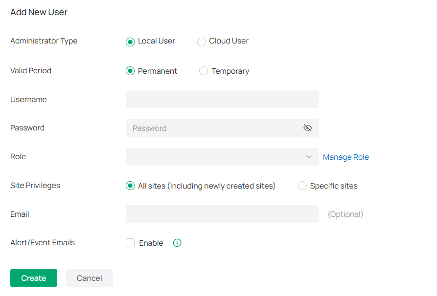
Step 3: Enable Notification in Site
1. Launch the controller and access a site.
2. Go to Logs, click the Setting icon in the upper right, then go to the Alerts or Events page.
3. Check the activity logs classified by the content and specify their notification categories as Alert or Event for the current site. Enable Email notification and/or Webhook notification for the logs if needed.
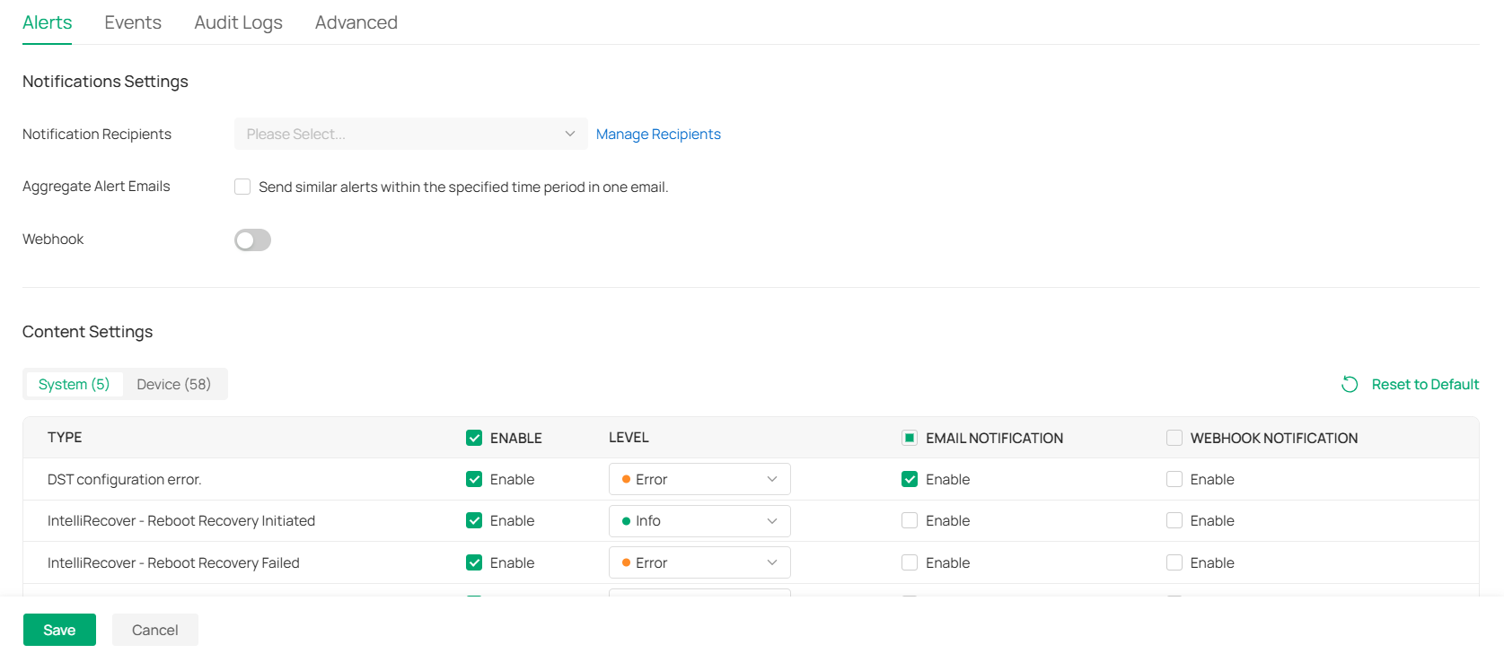
|
Notification Recipients |
Specify the recipients to receive alert/event notifications. |
|---|---|
|
Aggregate Alert Emails/ Aggregate Event Emails |
Enable this option and specify the time period. Similar alerts within the specified time period will be collected and sent in one email. |
|
Webhook |
Enable Webhook and choose a Webhook for the active push function of alerts/events. |
|
Reset to Default |
Click to reset all notification configurations in the current site to the default. |
|
|
Click the tabs to display the configurations of corresponding log types. |
|
Enable |
Check the box to specify an activity log as alert/event log. |
|
Email Notification |
Check the box to enable Email notification. The controller will send emails to notify the administrators and viewers of the site’s logs once generated. |
|
Webhook Notification |
Check the box to enable Webhook notification. The controller will push alerts/events once generated. |


4. Save the settings.
Configure Audit Log Notifications
To configure audit log notifications, follow the steps below:
Step 1: Create Webhooks
Launch the controller and access the Global View. Go to Settings > Platform Integration > Webhooks and create webhooks. For detailed configuration, refer to the section Webhooks in Platform Integration.
Step 2: Enable Webhook for Audit Logs
1. Launch the controller and access a site.
2. Go to Logs, click the Setting icon in the upper right, then go to the Audit Logs page.
3. Enable Webhook and choose webhooks.
4. Specify which categories will be sent to the corresponding log server via Webhook.
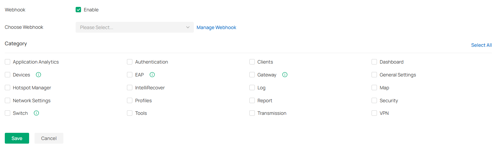
5. Save the settings.
Configure Remote Logging
With Remote Logging configured, the Controller will send the system logs to the specified log server once it is generated.
To configure Remote Logging, follow the steps below:
1. Launch the controller and access a site.
2. Go to Logs, click the Setting icon in the upper right, then go to the Advanced page.
3. Enable Remote Logging and configure the parameters.
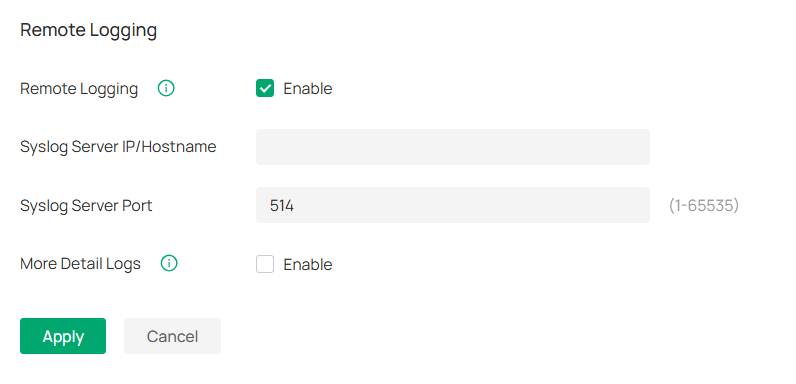
|
Syslog Server IP/Hostname |
Enter the IP address or hostname of the log server. |
|---|---|
|
Syslog Server Port |
Enter the port of the server. |
|
More Detail Logs |
With the feature enabled, the logs of AP clients and switch system will be sent to the Syslog Server. |
Maintain the Network with Tools
The controller provides many tools for you to analyze your network:
■ Network Check
Test the device connectivity via ping, traceroute, or DNSLookup.
■ Packet Capture
Capture packets for network troubleshooting.
■ Terminal
Open Terminal to execute CLI or Shell commands.
■ Cable Test
Perform cable test to check the cable issues.
■ Interference Detection
Scan for interference in the environment and obtain channel occupancy information.
Note:
Firmware updates are required for earlier devices to support these tools.
Network Check
1. Launch the controller and access a site.
2. Go to Network Tools > Network Check.
3. Configure the test parameters.
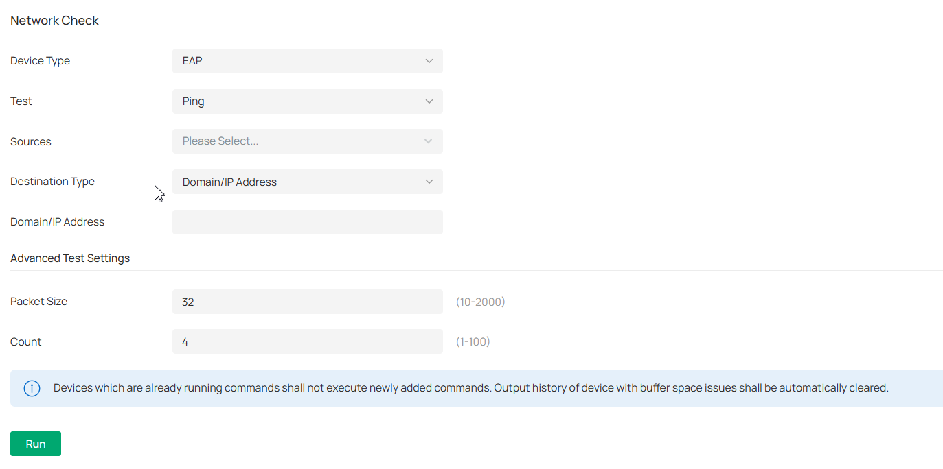
|
Device Type |
Select the device type to perform a test. |
|---|---|
|
Test |
Choose a tool to test the device connectivity. Ping: Tests the connectivity between the specified sources and destination, and measures the round-trip time. Traceroute: Displays the route (path) the specified sources have passed to reach the specified destination, and measures transit delays of packets across an Internet Protocol network. DNSLookup: Helps find DNS records of a domain name. ARP Table: Helps check the ARP table of the device. |
|
Sources |
Select one or multiple devices to perform a test. |
|
Destination Type |
Select the destination type and specify the destination to test. The options vary with the test type. For the Ping test, you can specify the Domain/IP Address or Client. Client is available only when an AP device performs the ping test. For the Traceroute test, you can specify the Domain/IP Address. For the DNSLookup test, you can specify the Domain. |
|
Advanced Test Settings |
(Only for the Ping test) Packet Size: Specify the size of ping packets. Count: Specify the number of ping packets. |
Note:
• Devices which are already running commands shall not execute newly added commands.
• Output history of device with buffer space issues shall be automatically cleared.
4. Click Run to perform the test. You can view the test result in the Device Output section.
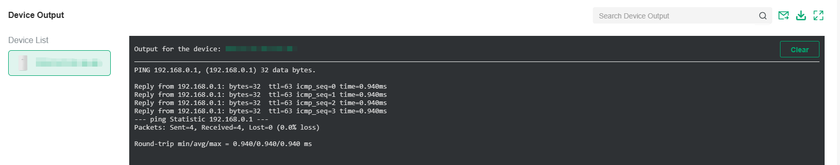
You can click the Email/Download/Zoom icons above the test result field to email the test logs to a mailbox, download the test logs locally, or zoom in/out the display area.
Packet Capture
1. Launch the controller and access a site.
2. Go to Network Tools > Packet Capture.
3. Configure the parameters for packet capture.
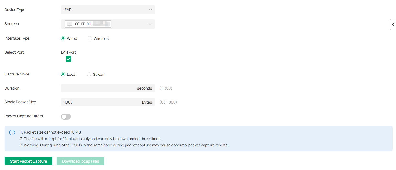
|
Device Type |
Select the device type to capture packets. |
|---|---|
|
Sources |
Select one or multiple devices to capture packets. |
|
Interface Type |
Select the interface type to capture packets. Wired: If selected, select the Port to capture packets and select the Capture Mode. Wireless: If selected, select Band and SSID / Interface to capture packets. Note: The following configurations will affect packet capturing on a wireless interface: |
|
Capture Mode |
Select a mode to capture packets: Local: The device executes the packet capture locally. The captured packets are packaged and stored in the internal directory of the device. You can download the file from the controller web page. Stream: The device does not save the packet capture files to the device’s internal storage, thereby avoiding memory consumption. Packets captured by the device can be displayed in real-time using packet capture tools such as Wireshark, enabling real-time viewing and analysis of the captured packets. |
|
Duration |
Specify the duration for packet capture. |
|
Single Packet Size |
Specify the size of a single captured packet. It cannot exceed 1 MB. |
|
Packet Capture Filters |
(Optional) Enter the filters to capture packets. Supported filters include: host, src, dst, tcp port, tcp src port, tcp dst port, udp port, udp src port, udp dst port, ether host, ether src, ether dst Combination of operators “and”, “or”, “(“ and “)” is supported between multiple filter items. For example: (src 192.168.0.1 and tcp port 80) or (src 192.168.0.1 and tcp port 90) (src 192.168.0.1 and tcp src port 80) or (dst 192.168.0.1 and tcp dst port 90) ether src A0:00:00:04:C5:84 and ether dst A0:00:00:04:C5:85 Note: host: host address, src: source, dst: destination, ether: ethernet address (MAC address) |
4. Click Start Packet Capture to capture packets. After packets are captured, you can click Download .pcap Files to download them.
Note:
The file will be kept for 10 minutes only and can only be downloaded three times.
Terminal
1. Launch the controller and access a site.
2. Go to Network Tools > Terminal.
3. Configure the parameters.
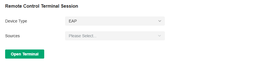
|
Device Type |
Select the device type to run CLI or Shell commands. |
|---|---|
|
Sources |
Select one or multiple devices to test. |
4. Click Open Terminal. Now you can run CLI or Shell commands.
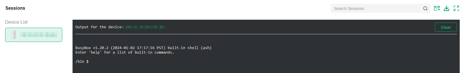
You can click the Email/Download/Zoom icons above the test result field to email the test logs to a mailbox, download the test logs locally, or zoom in/out the display area.
Cable Test
1. Launch the controller and access a site.
2. Go to Network Tools > Cable Test.
3. Configure the parameters.
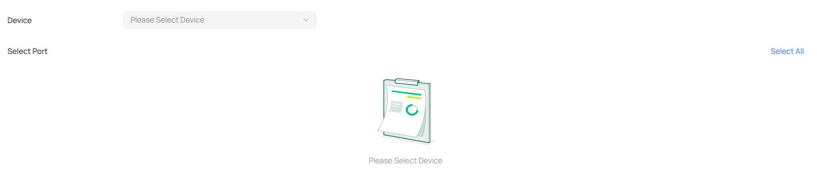
|
Device |
Select the device in the pop-up window to run the cable test. |
|---|---|
|
Select Port |
Select the port of the device to run the cable test. |
4. After running the cable test, you can check the diagnostic process and results below.
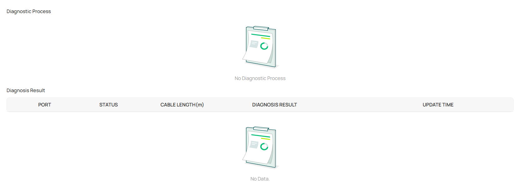
Interference Detection
Interference Detection is used to scan for interference in the environment and obtain channel occupancy information. After the scan is complete, it generates scan results that include channel utilization information and Wi-Fi interference source information.
There are two ways to configure the interference detection function: one for a single device and the other for multiple devices.
Method 1: Configure Interference Detection for Multiple Devices
Note:
After the scan is complete, a scan result entry will be generated and retained as a historical record that can be exported.
1. Launch the controller and access a site.
2. Go to Network Tools > Interference Detection.
3. Click the Interference Detection button.
4. In the pop-up window, select the devices to scan, and click Scan Now to start scanning.
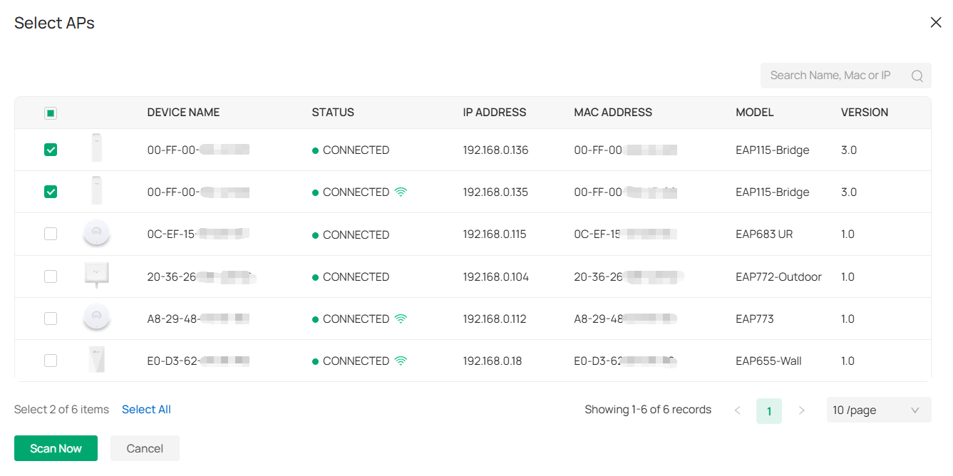
The Interference Detection page will display the detection records. You can click the Export icon of a record to export it if needed.
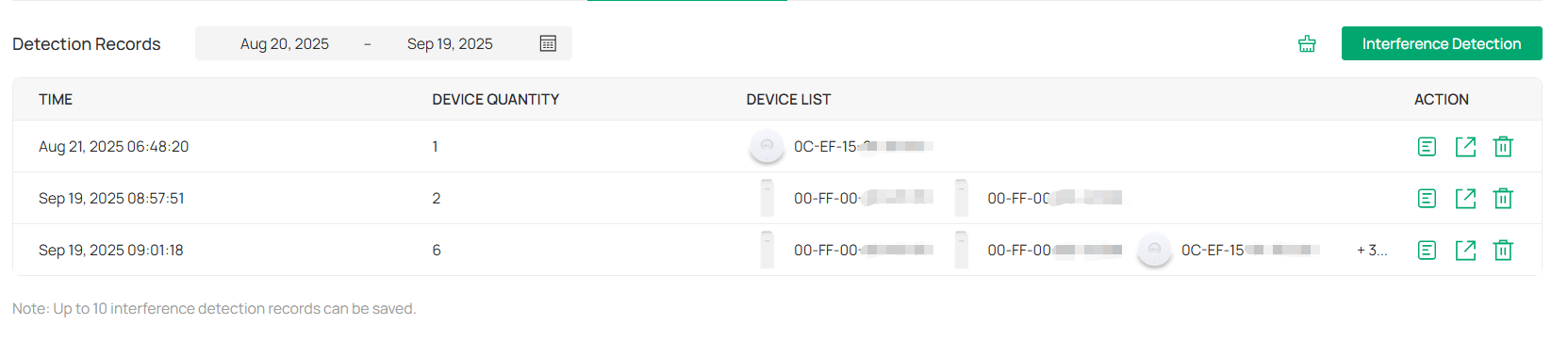
5. Click the Detail icon of a record to view the detailed results.
You can select All AP to view all device results or select a specific device to view its result. Click the band to view each band’s result.
Method 2: Configure Interference Detection for a Single Device
Note:
After the scan is complete, a scan result entry will be generated and overwrite the old entry, and the historical scan results will not be retained.
1. Launch the controller and access a site.
2. Go to Devices > Device List, click the target AP, and click Manage Device.
3. Go to Statistics > Interference Detection. Click Scan to start scanning.
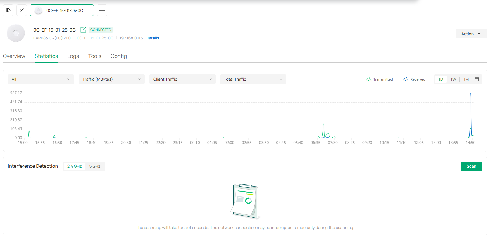
4. Wait for the scan to complete and the results will be displayed.
Maintain PoE Devices with IntelliRecover
Overview
IntelliRecover can help you monitor the status of PoE devices, automatically repairing abnormal devices.
Network Preparation:
• A PoE Switch that can be managed by Omada Controller;
• EAPs, security devices, or clients powered by the PoE switch.
Configuration
To configure IntelliRecover, follow these steps:
1. Launch the controller and access a site.
2. Go to Devices. After adopting the PoE switch, and the EAP or security device directly connected to the PoE switch, click the EAP or security device to open its Properties window. Click 
 then click IntelliRecover to enable the function for the device so that it can be added to the monitoring list.
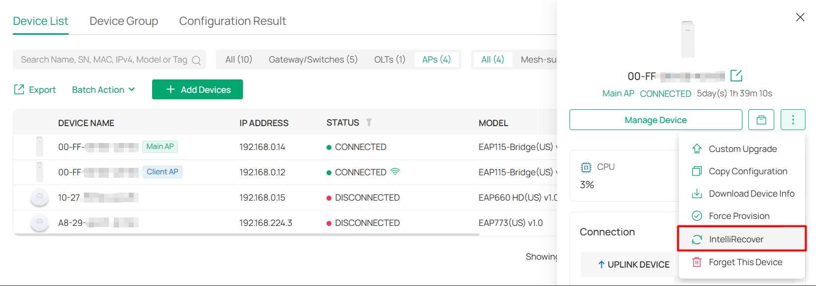
3. Go to Clients. Click the client device to open its Properties window. Click then click IntelliRecover to enable the function for the client so that it can be added to the monitoring list.
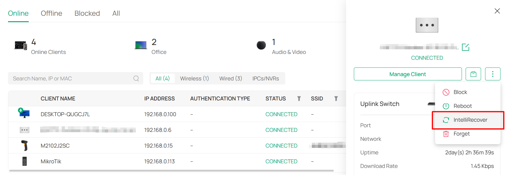
4. Go to the IntelliRecover page. Click Add to add the devices or clients to the monitoring list.
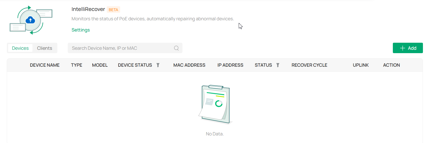
5. Select the devices or clients to be monitored and click Apply.
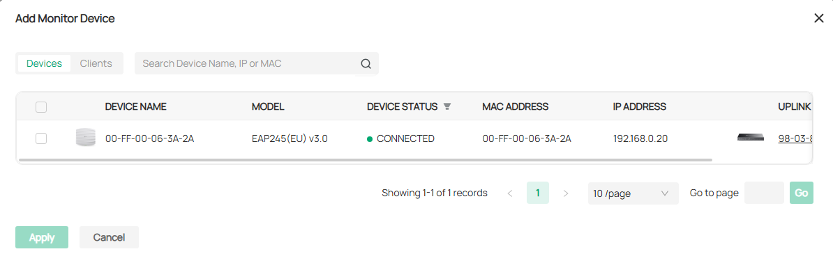
6. Click Settings on the IntelliRecover page and configure the parameters.
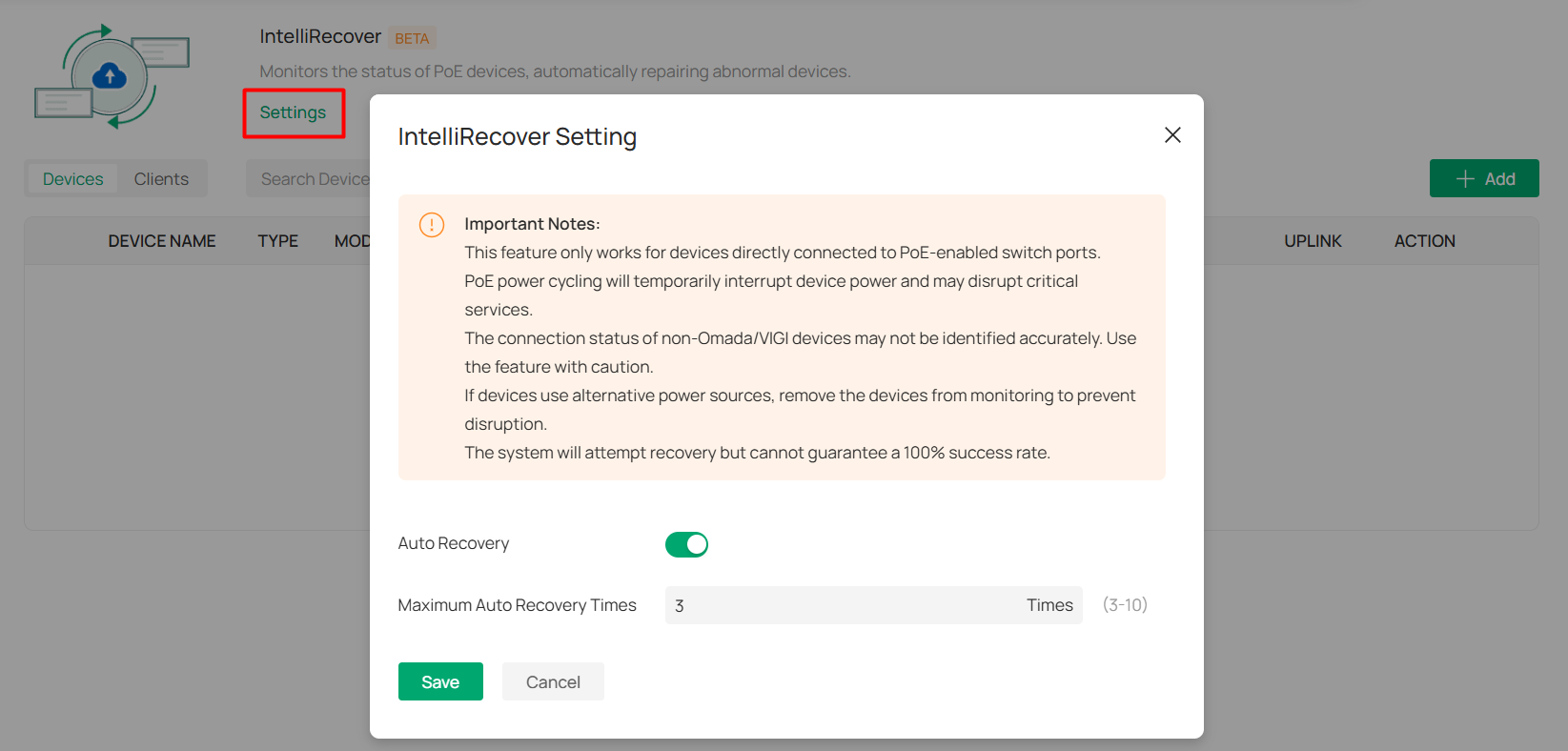
|
Auto Recovery |
Click to enable or disable the Auto Recovery funtion. |
|---|---|
|
Maximum Auto Recovery Times |
Specify the maximum auto recovery times for the monitored devices. When the limit has been reached, the monitered devices will not be automatically rebooted. |
7. After the configuration, when the monitored device goes offline, the switch PoE port connected to the device will be automatically rebooted and a log will be generated. You can also click the Reboot PoE Port icon in the Action column to manually reboot the PoE Port.
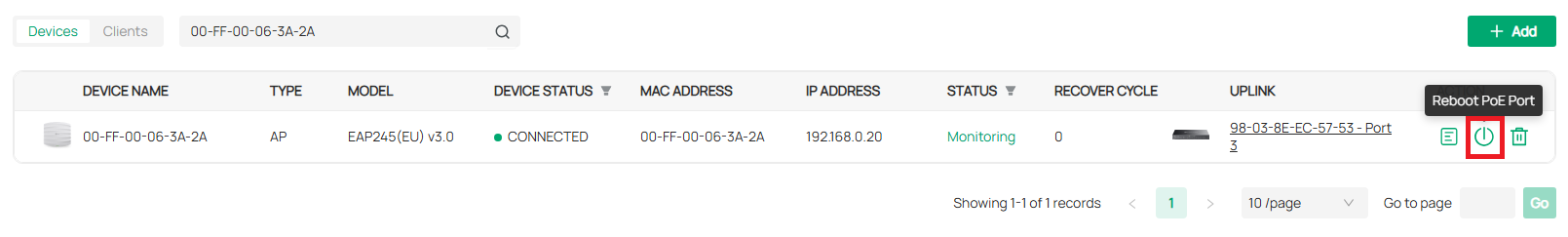
Managing Customer Networks in MSP Mode
This chapter will introduce how to enable MSP mode and manage customer networks in MSP view.
Overview
MSP (Managed Service Provider) mode allows you to know the status of your customers at a glance, and manage customers in the Omada platform.
■ Customer Monitoring
Keep you informed of accurate, real-time status of every customer.
■ Customer Management
Manage all customers to deploy the whole network.
■ Account Settings
Manage all administrative accounts.
Quick Start
Enable the MSP Mode
1. Launch the controller and access the Global View.
2. Go to Settings > Controller Settings. Enable MSP Mode and confirm the action to convert your standard controller system to an MSP system.

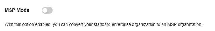

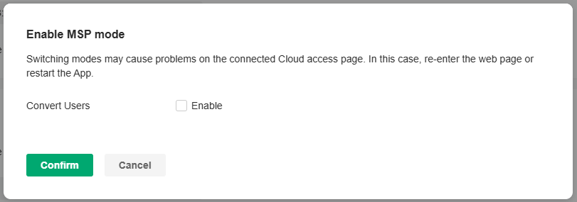
Note:
Enabling or disabling MSP mode may cause problems on the connected Cloud access page. In this case, re-enter the web page.
3. You will enter the MSP view.

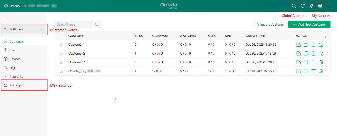
Add and Manage Customers
1. In MSP View, go to the Customer page.
2. Add customers by using one of the following methods:
• Add a new customer
Click Add New Customer above the customer list. Specify the customer name and enter a description. Then save the settings.

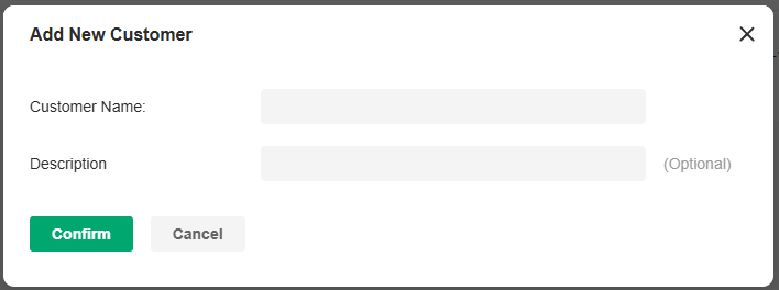
• Copy an existing customer
Click the Copy icon of a customer entry. Specify the customer name and enter a description. Then save the settings.

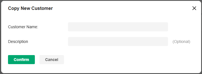
• Import customers from another controller
Click Import Customer above the customer list. Specify the customer name and enter a description. Determine whether to retain device info according to your needs. Then import customer from a local file or from a file server.

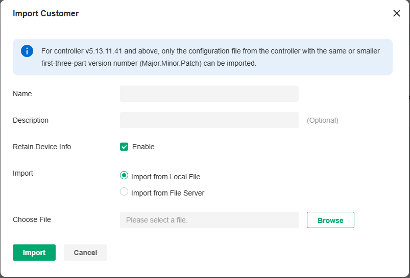
3. The new customers will be added to the customer list and the drop-down list of Customers.
In the customer list, you can view the customer information, and click the icons in the ACTION column to manage customer entries and launch the controller of each customer.

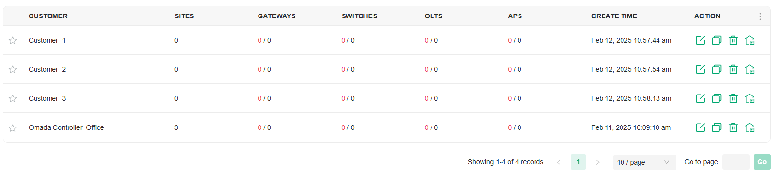
Add Sites and Devices
1. Select a customer then click Global from the Customer drop-down list in the left of the page.

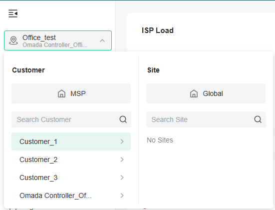
2. Add sites and adopt devices by referring to Getting Started with Omada Network.
Add and Manage MSP Accounts
Similar as a common controller, the controller in MSP mode offers multiple levels of access available for users: MSP Owner, MSP Super Administrator, MSP Administrator, and MSP Viewer. You can also create new account roles and customize their permissions to access different features.
You can use the MSP roles and user accounts on a controller in MSP mode in the same way as using the roles and user accounts on a standard controller. For more information, refer to Managing Accounts.
Configuring the SD-WAN
This chapter will introduce how to configure the SD-WAN to easily connect multiple gateways of sites.
Introduction to SD-WAN
SD-WAN, or Software-Defined Wide Area Network, allows you to easily connect multiple gateways together without complicated VPN configuration. It helps reduce wide area network expenses, improve network connection flexibility, and provide secure and reliable interconnection services for enterprise networks and data center networks scattered across a wide geographical range.
Omada Controller implements SD-WAN networking based on the Hub-Spoke mode, which allows you to quickly establish network connections between multiple sites; it also supports setting up direct channels between specified sites to improve communication efficiency.
Requirements
To use SD-WAN, ensure the following:
• At least one gateway in your network is configured with a public IP address.
• The WAN networks of the gateways have not enable DMZ.
• The network segments in the network do not conflict with each other or the LAN of other sites.
Configure the SD-WAN
1. Adopt the gateway that is configured with a public IP address through the LAN side.
2. Configure port forwarding on the adopted gateway for adoption of other gateways.
a. Access the site where the gateway is adopted. Go to Network Config > Transmission > NAT > Port.
b. Add a Port Forwarding rule for the controller port, as shown in the following figure:

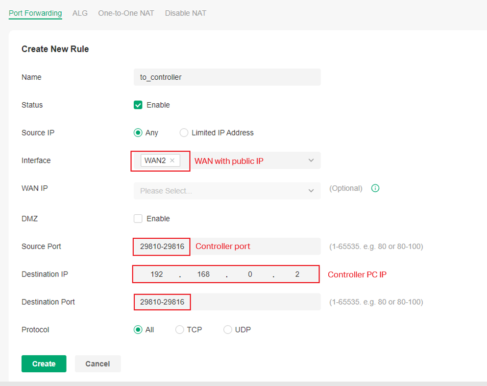
c. If you need to upgrade devices through the controller, add a port forwarding rule for upgrade port 8043, as shown in the following figure:
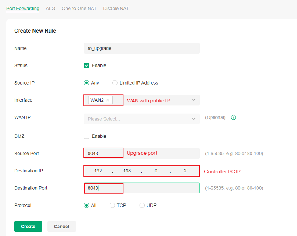
3. Adopt other gateways through the WAN side.
a. On the standalone page of each gateway, set the Controller Inform URL/IP to the public IP of the gateway adopted on the LAN side, as shown in the following figure:
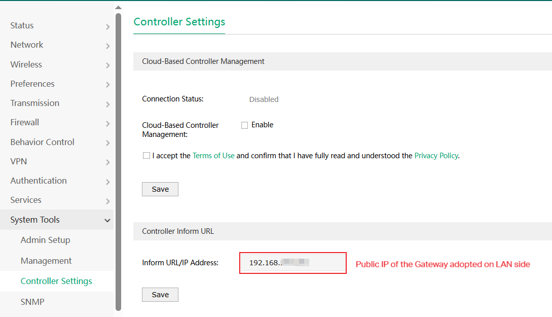
b. On the controller page, create a site for each gateway and adopt them to the sites.
4. Configure SD-WAN.
a. In Global View, go to SD-WAN. Click Create SD-WAN Group.
b. Configure basic settings, then click Next.
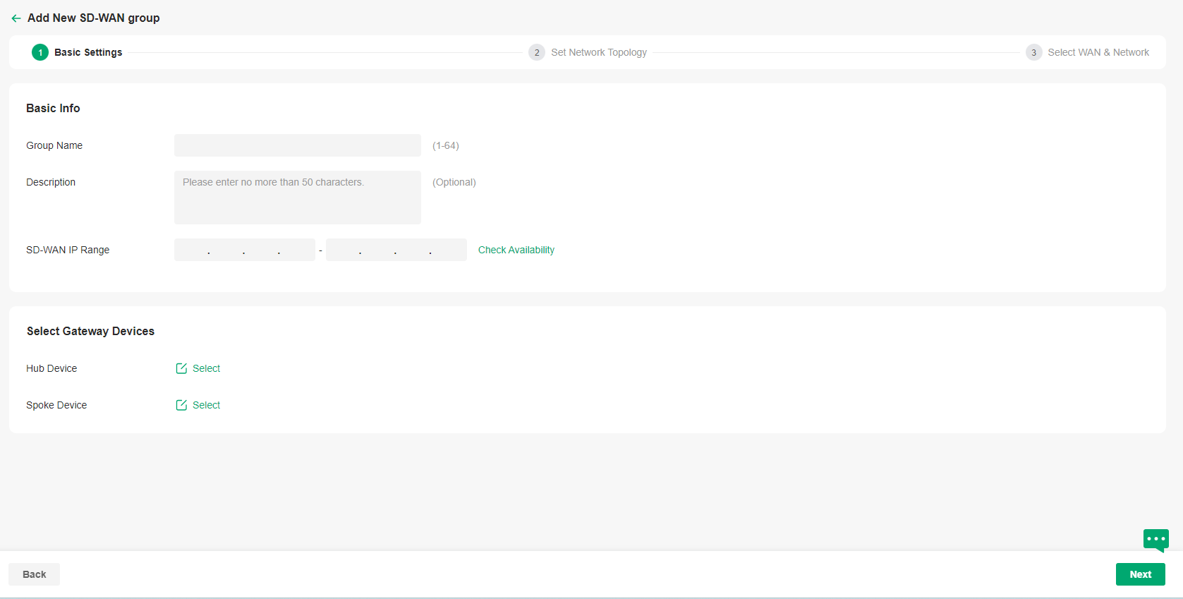
|
Group Name |
Specify the name of the group. |
|---|---|
|
Description |
Enter a description for identification. |
|
SD-WAN IP Range |
Specify the IP range for the controller to assign virtual IP addresses to VPN interfaces. Ensure the IP range contains at least 16 IP addresses. After filling in the information, click Check Availability to perform conflict detection on the IP range. |
|
Hub Device |
Click to select a hub device from the listed gateways. Only the gateways with public IP addresses will be listed. |
|
Spoke Device |
Click to select spoke devices from the listed gateways. |
c. Set the network topology. It is recommended to click Manage Spoke-Spoke Connection to create connections between spokes to reduce the pressure on the hub. Click Next.
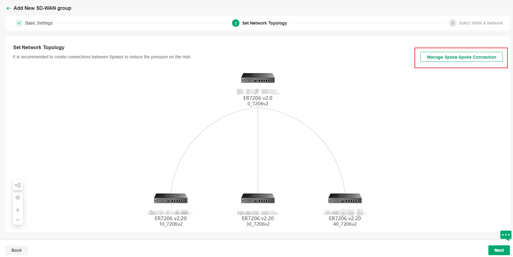

d. Select WAN and network. Then click Next.
|
WAN Port |
Click Auto Select WAN Port and the controller will automatically select a WAN with a public IP or a WAN with the smallest number of ports and an IP for each gateway. You can also customize the configuration for each gateway. |
|---|---|
|
Network Segment |
This controller automatically adds the Default LAN of each gateway to the Network Segment. You can also customize the configuration for each gateway. Ensure all network segments in the network do not conflict with LANs in other sites. |

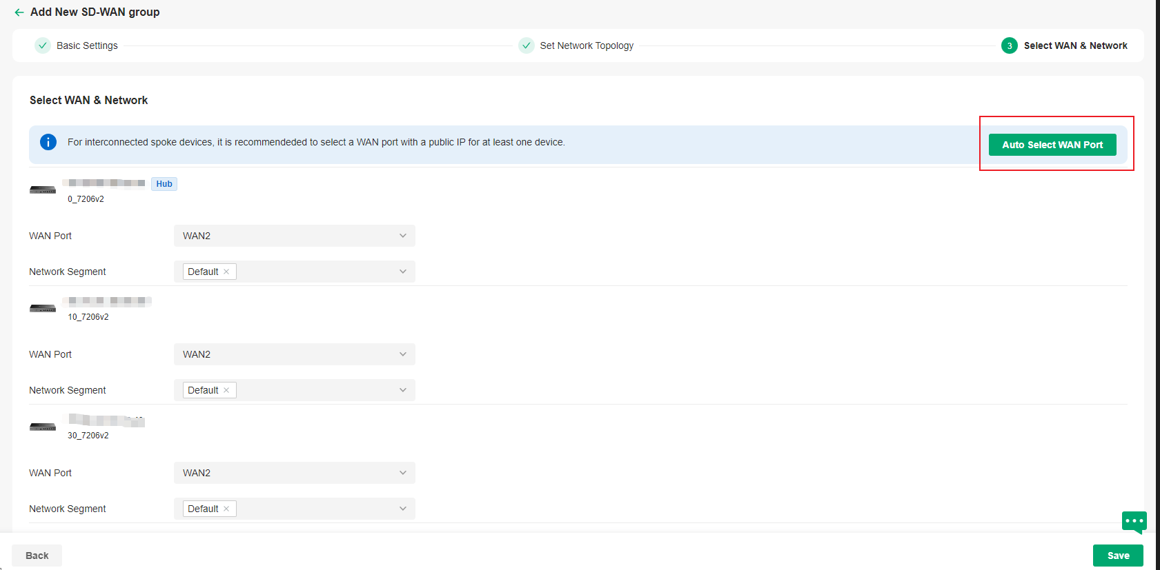
e. Save the settings. The SD-WAN group will be added.
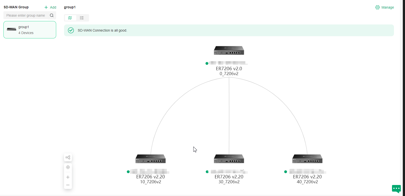

Configuring Multi-Controller Clusters
This chapter will introduce how to configure multi-controller clusters.
Introduction to Multi-Controller Clusters
A multi-controller cluster is a group of interconnected controllers that work together as a single system to enable high availability and can be recognized as a Cluster System. Each controller (node) in the cluster works on a part of the task. If one controller fails, others will take over tasks, preventing system interruptions. This reduces the impact of controller failures on authentication and other online services and facilitates centralized management across multiple controllers.
Omada Controller supports two cluster modes:
■ Hot-Standby Backup Mode
In this mode, there is a primary node and a secondary node. Generally, the primary node is responsible for network management and process running, while the secondary node synchronizes data with the primary node. If the primary node goes down, the secondary node will take over network and clients management. During the failover, the devices will go offline for a short time, then they will reconnect to the new primary node when the devices get connected again, all services will run normally. If the previous primary node recovers from failover, it will continue to run as a secondary node.
Note:
• For OC300, the management scale will be reduced to half its original size after enabling Hot-Standby Backup Mode.
• For Linux system, ensure the primary node and secondary node server configurations are the same. The new primary node after switching nodes will remain unchanged until the next switch.
■ Distributed Cluster Mode
In this mode, multiple nodes collaborate to manage Omada devices. This collaborative approach not only significantly increases the upper limit of the number of devices that the Controller can manage, but also, through the coordinated operation of multiple nodes, ensures the high - availability of the entire network. If a node failure occurs, automatic load balancing will be triggered, and the services of the failed node will be taken over by other nodes. During the failover period, the devices under the site managed by the original failed node will be briefly offline and then automatically reconnect to other nodes. Once the devices resume the “Connected” state, all services will operate normally.
Below is a typical distributed cluster deployment topology, where multiple nodes (three nodes or more) can jointly manage Omada devices.
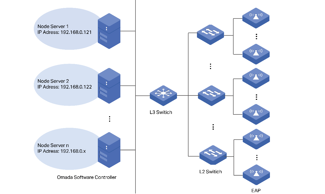
Configure Hot-Standby Backup Clusters
Requirements
• Omada Software Controller (Linux, v5.15.20 and above) / Omada Hardware Controller (OC300 / OC400, Built-in Controller v5.15.20 and above)
• Linux System (Ubuntu 20.04/22.04)
Prerequisites and Precautions
• Ensure the JDK and MongoDB versions are consistent across all nodes.
• Set static IP addresses for your controllers. For Linux Controller, it is recommended to set static IP before enabling Cluster Mode to avoid abnormalities in the connections between nodes due to dynamic IP changes. For Hardware Controller, it’s a mandatory requirement that the IP of nodes should be static under Cluster Mode.
• It is recommended to deploy all nodes within the same network segment.
• The original data of the secondary node will be overwritten by the data of the primary node. The settings will take effect after rebooting. This process involves data synchronization and may take a long time.
• If you are using hardware controller, during startup, the secondary node needs to successfully connect to the primary node before it can continue to startup, and the web page of Hardware Controller may be unresponsive for a long time.
Configuration
1. (For Linux Controller) Modifying the handle count of the system is a prerequisite for using the Controller Hot-Standby Backup Mode. Edit /etc/security/limits.conf, add the following parameters, save the file, log out and log back in to make the changes take effect.
* soft nofile 65535
* hard nofile 65535
Note:
The methods of modifying handle number may vary by Linux version. Please modify the handle number according to Linux version.
2. Set static IP addresses for your controllers, and keep them in the same subnet.
• For Linux Controller, it is recommended to set static IP before enabling Cluster Mode to avoid abnormalities in the connections between nodes due to dynamic IP changes.
• For Hardware Controller, it’s a mandatory requirement that the IP of nodes should be static under Cluster Mode.
3. Configure cluster settings.
a. In Global View, go to Settings > Cluster, and enable Cluster.
b. For the primary node, select the mode as Hot-Standby Backup. Input the IP address of the primary node in the Local IP/Hostname field and the IP address of the secondary node in the Remote IP/Hostname field. Choose Primary as Initial Status. Customize the Key and remember it.
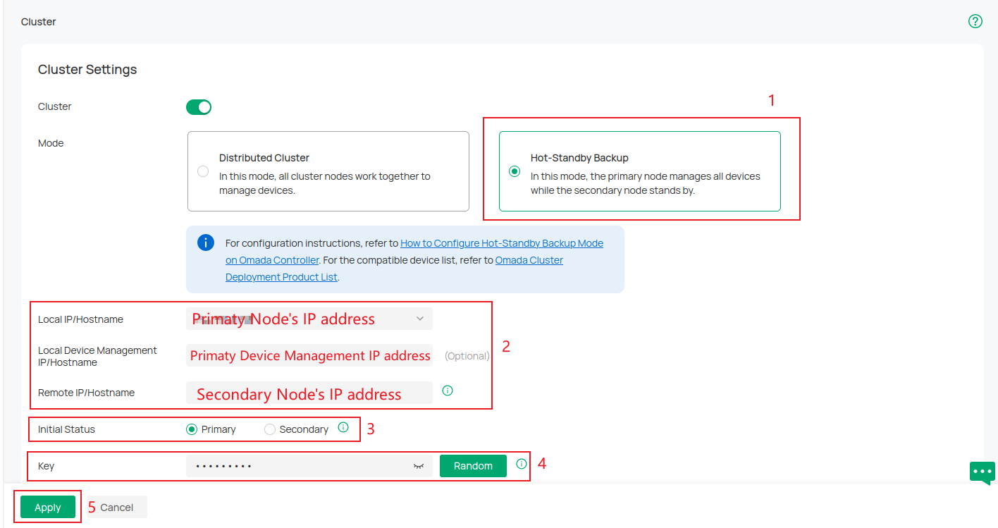
c. For the secondary node, select the mode as Hot-Standby Backup. Input the IP address of the secondary node in the Local IP/Hostname field and the IP address of the primary node in the Remote IP/Hostname field. Choose Secondary as Initial Status. Input the same Key as the primary node's.
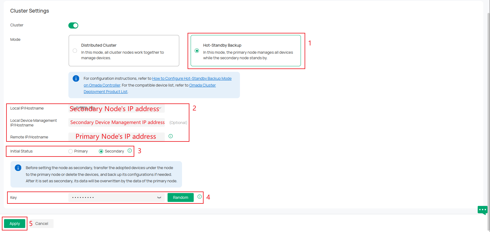
Note:
If you are going to set one running controller as the secondary node, migrate all the devices of this controller to the primary node or forget them all. It is recommended to back up your configuration before cluster configuration. After it’s set as secondary node, its data will be overwritten by the data of the primary node.
4. Reboot the primary node and the secondary node.
• For Hardware Controller, just reboot the Controller with the Reboot feature.
• For Linux Controller, use the sudo tpeap restart command on your Linux System:
The cluster will be established after the nodes reboot.
For more instructions and related FAQs, refer to How to Configure Hot-Standby Backup Mode on Omada Controller.
Configure Distributed Clusters
Requirements
• Omada Software Controller (Linux, v5.15.20 and above)
• Ubuntu 22.04
• JAVA17
• Mongodb v7.0
Prerequisites and Precautions
• The Distributed cluster mode requires at least three nodes. Prepare to deploy at least three controllers before setting it up.
• Installing the distributed cluster mode requires Java 17. Use the sudo apt install openjdk-17-jre-headless command to install Java 17.
• Modifying the handle count of the system is a prerequisite for using the Controller distributed cluster mode. Edit /etc/security/limits.conf, add the following parameters, save the file, log out and log back in to make the changes take effect.
* soft nofile 65535
* hard nofile 65535
• The methods of modifying handle number may vary by Linux version. Please modify the handle number according to Linux version.
• Ensure the system time of each node is consistent, with a time difference of less than 20 seconds.
• Ensure the JDK and MongoDB versions are consistent across all nodes.
• Node IPs only support static IPs. If you need to modify the IP/port, you will need to re-initialize.
• It is recommended to deploy all nodes within the same network segment.
Configure an Existing Controller via Web
1. In Global View, go to Settings > Cluster and enable Cluster. Then select the mode as Distributed Cluster.
2. Click Add Node to add at least three nodes.
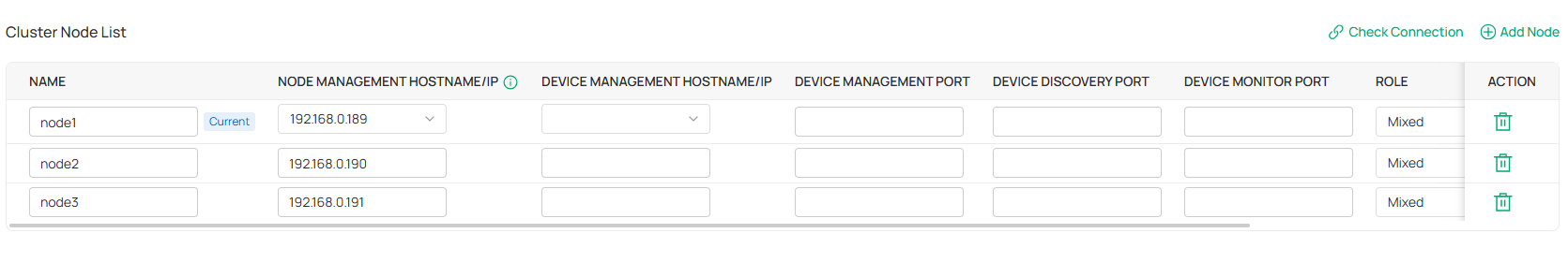
Input these nodes’ name and node management hostname/IP. Here, hostnames/IPs should correspond to different servers.
Specify the device management hostname/IP of the management device. This IP address will be used to establish a connection and communicate with the device. If it is not specified, the node management hostname/IP will be used by default.
Specify the device management port, device discovery port, and device monitor port. Ensure they don’t conflict with ports already used by the PC.
Then click Apply.
After that, Controller will pop up a prompt window and the init properties file. Download the init properties file and reboot the Controller for the settings to take effect.
Note:
• Please reboot nodes as soon as possible to prevent device disconnection or other problems.
• Nodes added offline will be considered down - state nodes, which will affect the disaster recovery capability. Please initiate them as soon as possible.
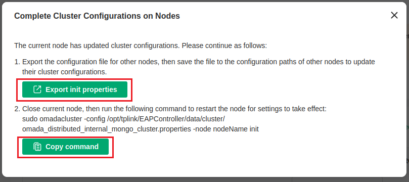
3. Replace the properties file you downloaded at each node respectively. The path to the properties file is:
/opt/tplink/EAPController/data/cluster/omada_distributed_internal_mongo_cluster.properties
4. Execute the initialization command on each node respectively. When initializing nodes, set the account and password for all nodes. When initializing nodes, first initialize the primary node (the one exporting init properties). Otherwise, initialization may fail.
sudo omadacluster -config
/opt/tplink/EAPController/data/cluster/omada_distributed_internal_mongo_cluster.properties -nodeName init
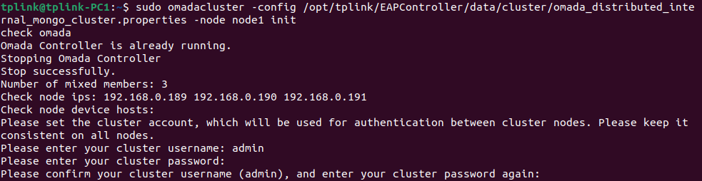
5. After the deployment is successful, go to the Cluster page to confirm. And when the distributed cluster mode is running properly, you can access the Controller through any node.
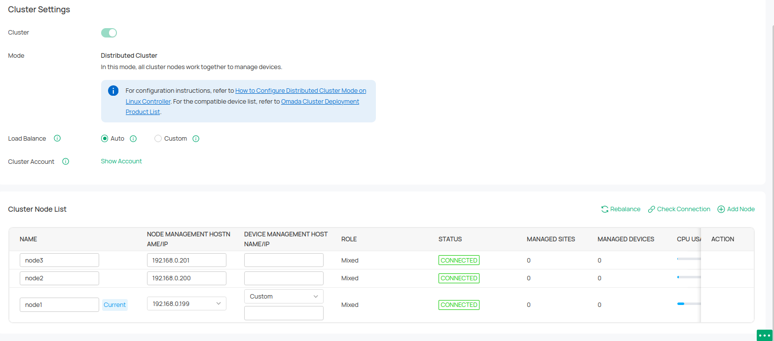
Configure a New Controller via Commands
1. Select cluster mode installation (does not automatically start after installation).
• Install using deb
echo “omadac omadac/init-cluster-mode boolean true” | sudo debconf-set-selections
sudo dpkg -i /path/to/controller_installation_package

• Install using tar.gz
After decompression, deploy the cluster mode via the shell installation script. Enter ./install.sh init - cluster – mode, the system will not start automatically after installation, and relevant prompt information for setting up the cluster will be printed.

2. Start installing the Controller and edit the properties file as prompted.
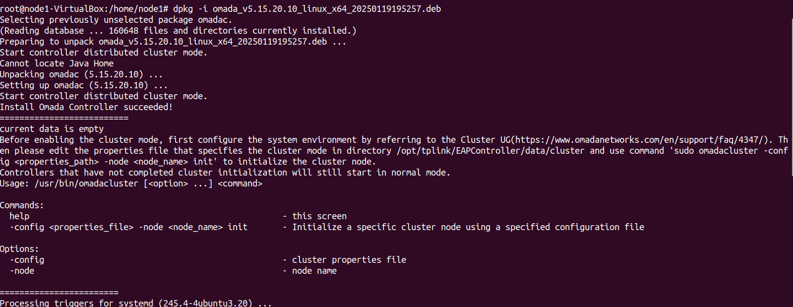
Modify each node’s properties file /opt/tplink/EAPController/data/cluster/omada_distributed_internal_mongo_cluster.properties
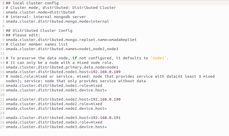
3. Execute the initialization command on each node respectively.
sudo omadacluster -config /opt/tplink/EAPController/data/cluster/omada_distributed_internal_mongo_cluster.properties -node <nodeName> init
4. After the deployment is successful, log in to the Controller and set the username and password, and other nodes will synchronize the username and password.
Then go to the Cluster page to confirm. And when the distributed cluster mode is running properly, you can access the Controller through any node.

For more instructions and related FAQs, refer to How to Configure Distributed Cluster Mode on Linux Controller.
