


Contents
Configure STP on Omada Controller
Configure MSTP on Omada Controller
Configure RPVST on Omada Controller
Introduction
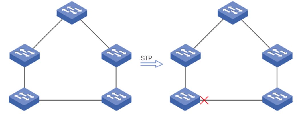
Spanning Tree Protocol (STP) is a Layer 2 Protocol that prevents loops in the network. As shown below, STP helps to:
- Block specific ports of the switches to build a loop-free topology.
- Detect topology changes and automatically generate a new loop-free topology.
Rapid Spanning Tree (RSTP) provides the same functionality as STP with much faster spanning tree convergence and is, therefore, more recommended.
Multiple Spanning Tree Protocol (MSTP) also provides the fast spanning tree convergence as RSTP. In addition, MSTP enables VLANs to be mapped to different spanning trees (MST instances), and traffic in different VLANs will be transmitted along their respective paths, implementing load balancing.
Rapid Per-VLAN Spanning Tree+ (RPVST) maintains an independent spanning tree per VLAN. It uses RSTP for rapid convergence to avoid L2 loops, thus improving link utilization and fault recovery in multi-VLAN environments. Additionally, it is fully compatible with PVST and PVST+.
Omada managed switches support STP/RSTP/MSTP, some of them also support RPVST, this article will describe how to configure them via Omada Controller.
Note: If not explicitly stated, STP in the following refers to both STP and RSTP.
Requirements
- Omada Switches (Omada Campus Switches / Omada Aggregation Switches / Omada Access Max Switches / Omada Access Pro Switches / Omada Access Plus Switches / Omada Access Switches)
- Omada Controller (Omada Network Application / Hardware Controller / Omada Cloud-Based Controller, V6.2.10 and above)
Configuration
Configure STP on Omada Controller
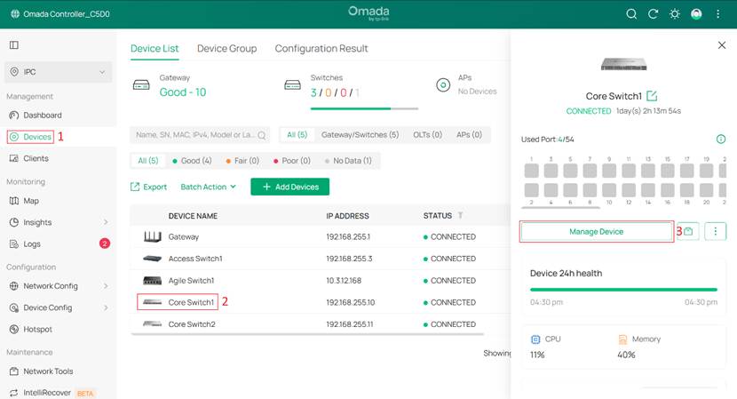
Step 1. Enable STP for devices.
Click the switches one by one on the Devices page, then go to Manage Device > Config > Services.
Set Spanning Tree to STP/RSTP, and configure other parameters as needed.
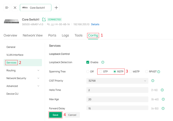
CIST Priority: Determines the root bridge election in the spanning tree. A smaller value indicates higher priority, and the switch with the highest priority will be elected as the root bridge.
Hello Time: The interval for sending BPDUs to detect link failures. It works with Max Age to monitor link status and maintain the spanning tree.
Max Age: The aging time of BPDU packets, which refers to the maximum duration a switch will wait to regenerate a new spanning tree if no BPDUs are received.
Forward Delay: When a link failure triggers spanning tree recalculation, the new configuration messages generated from the recalculation cannot propagate throughout the network immediately. After a delay of twice the Forward Delay interval, this latency ensures that new configuration messages have fully propagated across the network, thus preventing the formation of temporary loops.
Tx Hold Count: Limits the number of BPDUs that can be transmitted by a switch within a single Hello Time interval. This mechanism prevents excessive BPDU transmission during frequent topology changes, helping to avoid unnecessary network load and ensuring stable spanning tree operation.
Note: Loopback Detection and Spanning Tree can be enabled on the same device, but they cannot be enabled on the same port simultaneously.
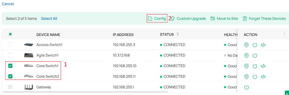
Alternatively, you can click Batch Action > Batch Config.
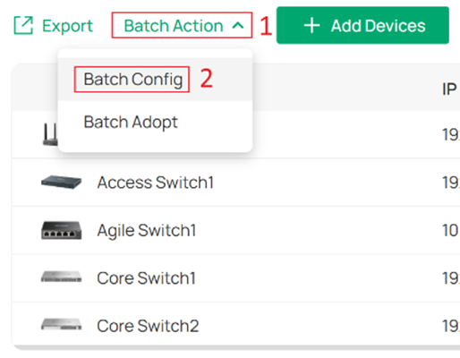
Select multiple switches, and then click Config to configure them in batch.
Set Spanning Tree to STP/RSTP, and configure other parameters as needed.
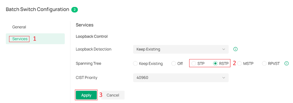
After that, configure the CIST Priority individually on the switches where needed.
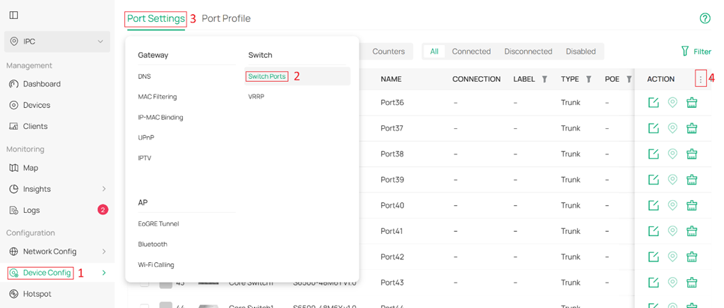
Go to Device Config > Switch > Switch Ports > Port Profile.
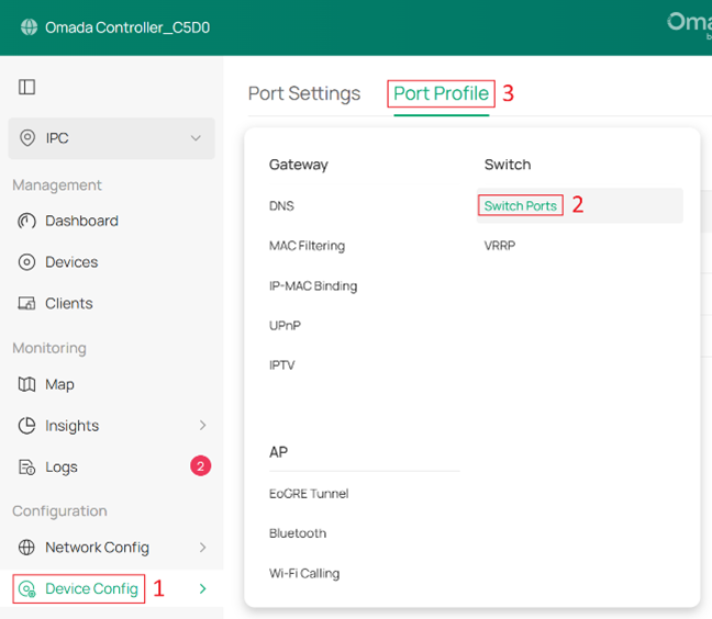
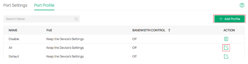
You can create a new profile via +Add Profile or edit an existing profile.
Set Loopback Control to Spanning Tree.
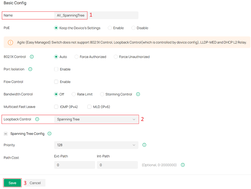
Priority: Determines the port priority used in spanning tree path selection. A smaller value indicates higher priority, reducing the likelihood of the port being blocked.
Path Cost: External Path Cost determines the root port selection (lowest cost path to the root bridge). Internal Path Cost is used in MSTP to select the root port within an IST (Internal Spanning Tree).
Edge Port: Edge ports transition directly from blocking to forwarding during topology changes. Configure ports connected to end devices (e.g., PCs) as edge ports.
P2P Link: Defines whether the port operates as a point-to-point link. Point-to-point links allow RSTP to perform rapid state transitions for faster convergence.
STP Security:
- Loop Protect: Ports with Root/Alternate/Backup roles enter error-disabled blocking if no BPDUs are received. Automatically recovers when BPDUs resume. Enable this on Root/Alternate/Backup ports.
- Root Protect: Ports enter error-disabled blocking upon receiving superior BPDUs. Automatically recovers when superior BPDUs stop. Enable on Designated ports; avoid enabling on Root/Alternate/Backup ports (may cause device unmanageability).
- TC Guard: When enabled, ports do not flush MAC address tables upon receiving TC (Topology Change) notifications.
- BPDU Protect: Manually configured edge ports enter error-disabled blocking upon receiving BPDUs. Requires manual recovery. Enable on Edge Ports.
- BPDU Filter: When enabled, ports neither send nor process BPDUs, disabling loop prevention. Use only on network-edge ports with no loop risk. Enabling on Root/Alternate/Backup ports risks broadcast storms.
- BPDU Forward: BPDU Forward will take effect only when the Spanning Tree is disabled for the entire device.
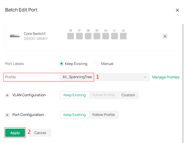
Then go to Port Settings. Edit ports one by one, or select multiple ports and click Edit Selected.
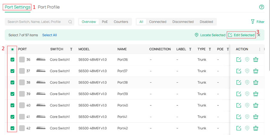
Assign the profile you just modified or created to the selected ports.
Step 3. Check Operation Status.
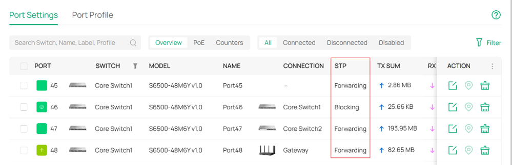
On Omada switches, port states include Blocking, Learning, Forwarding, and Disconnected, as explained below:
- Blocking: The port is blocked. It can receive and send BPDUs, while all other packets are dropped.
- Learning: The port receives and sends BPDUs, and also receives user packets to update its MAC address table, but does not forward them. This is a transitional state.
- Forwarding: The port operates normally. It receives and sends BPDUs, processes user packets, updates the MAC address table, and forwards traffic.
- Disconnected: The port has STP enabled but is not connected to any device.
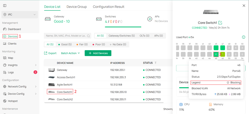
There are two places in Omada Controller to view switch port states:
Method 1. On the Devices page, click a switch. Blocked ports will be displayed with the status Blocking.
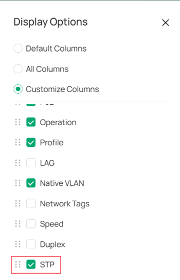
Method 2. Go to Device Config > Switch > Switch Ports > Port Settings, select STP, and the STP states of all active ports will be listed.
Configure MSTP on Omada Controller
This section describes the configuration steps.
Step 1.(Optional) Create multiple VLANs.
MSTP can run within a single VLAN network. However, to demonstrate the features of MSTP, we will create a new VLAN.
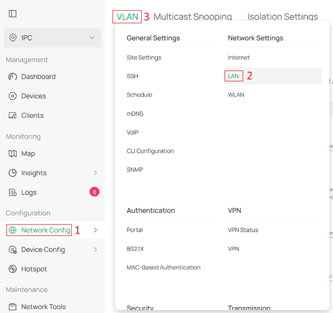
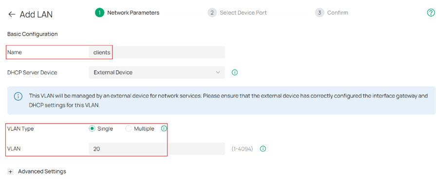
Go to Network Config > Network Settings > LAN > VLAN, and click +Add to create a new VLAN.
Set the Name to clients, the VLAN ID to 20, and configure other parameters as needed.
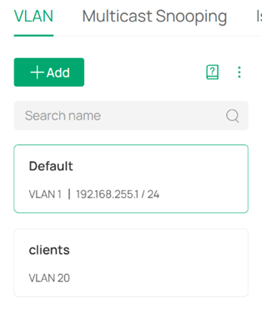
Now, there are two VLANs: Default (VLAN 1) and clients (VLAN 20).
Step 2. Enable MSTP for devices.
The configuration path is the same as STP. Please refer to Step 1 under Configure STP on Omada Controller.
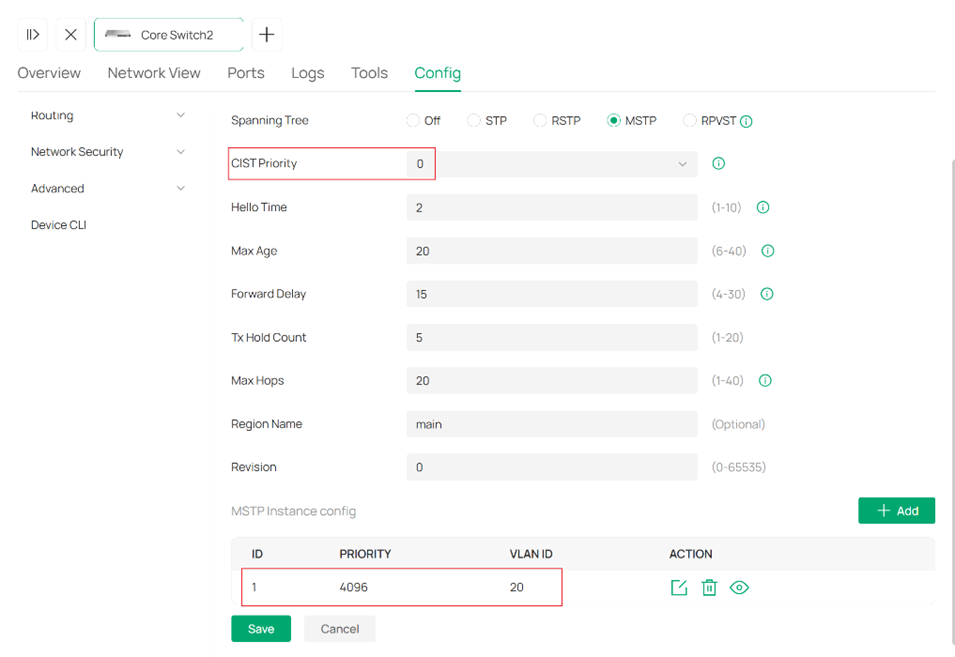
Set Spanning Tree to MSTP, configure the CIST Priority to 4096, set the Region Name to main, and configure other parameters as needed. Then click +Add to create an MSTP instance.
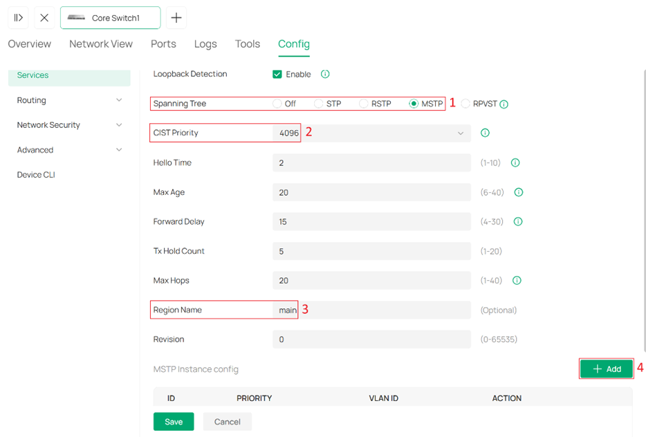
Max Hops: BPDUs are discarded when their hop count reaches zero. This value controls the scale of the spanning tree in an MST region. Switches decrement the hop count by 1 before forwarding BPDUs.
Region Name: Switches with the same region name, along with matching VLAN-to-instance mappings and revision number, are considered part of the same MST region and can share a common spanning tree topology.
Revision: This value is used to ensure consistency of MST configuration among switches. Switches must have the same revision level, in addition to the same region name and VLAN mapping, to be recognized as part of the same MST region.
Set MSTP Instance ID to 1, Priority to 0, and VLAN ID to 20. Click Apply to complete the MSTP Instance creation, then click Save to apply the settings.
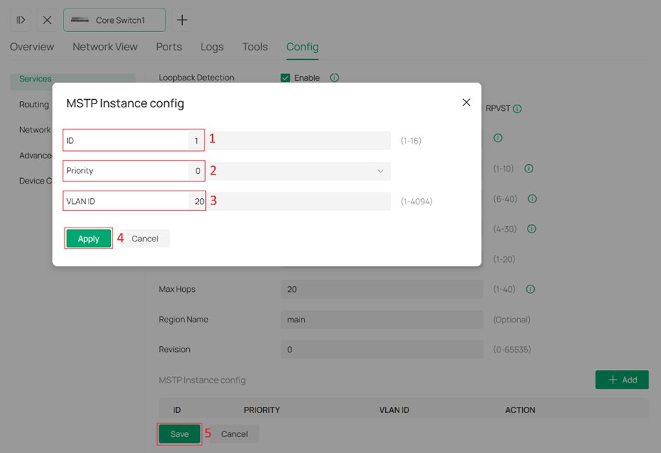
Note: the VLAN ID can include multiple entries. Format example: 1,3,4-7,11-30.
Configure another Omada switch with mostly the same settings. The differences are:
- CIST Priority to 0
- Priority of MSTP Instance 1 to 4096
Note: VLANs that are not assigned to any Instance ID will be mapped to the CIST instance. In this article, Default (VLAN 1) is not assigned to any instance, so it is mapped to CIST instance.
Step 3. Enable MSTP for ports.
The configuration path is the same as STP. Please refer to Step 2 under Configure STP on Omada Controller.
You can enable Instance/VLAN Priority to configure individual port Priority and Path Cost values for each instance.


Note: If Instance/VLAN Priority is not enabled, or if only some instances are configured with individual port Priority and Path Cost settings, the remaining instances will use the default values.
Step 4. Check Operation Status
You can use the same method as STP to view the operation status of the CIST instance. Please refer to Step 3 under Configure STP on Omada Controller.
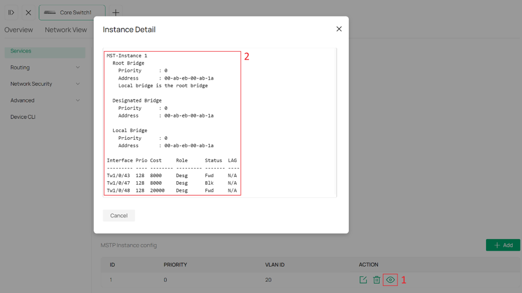
To view the operation status of other instances in MSTP, go to the MSTP configuration page and click the eye icon in the Action column for each instance entry.
Configure RPVST on Omada Controller
Step 1.(Optional) Create multiple VLANs.
RPVST can run within a single VLAN network. However, to demonstrate the features of RPVST, we will create a new VLAN.
Please refer to Step 1 under Configure MSTP on Omada Controller.
Step 2. Enable RPVST for devices.
The configuration path is the same as STP. Please refer to Step 1 under Configure STP on Omada Controller.
Set Spanning Tree to RPVST, configure the Priority of VLAN 1 and VLAN 20, and configure other parameters as needed. Then click Save to apply the settings.
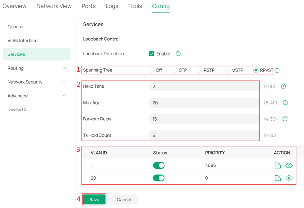
Hello Time: The interval for sending BPDUs to detect link failures. It works with Max Age to monitor link status and maintain the spanning tree.
Max Age: The aging time of BPDU (Bridge Protocol Data Unit) packets, which refers to the maximum duration a switch will wait to regenerate a new spanning tree if no BPDUs are received.
Forward Delay: When a link failure triggers spanning tree recalculation, the new configuration messages generated from the recalculation cannot propagate throughout the network immediately. After a delay of twice the Forward Delay interval, this latency ensures that new configuration messages have fully propagated across the network, thus preventing the formation of temporary loops.
Tx Hold Count: Limits the number of BPDUs that can be transmitted by a switch within a single Hello Time interval. This mechanism prevents excessive BPDU transmission during frequent topology changes, helping to avoid unnecessary network load and ensuring stable spanning tree operation.
Note: RPVST is supported only on the S6500 series, S7500-26XFY, and S7500-24Y4C, and requires firmware versions recommended for Omada Controller V6.2.10 and above.
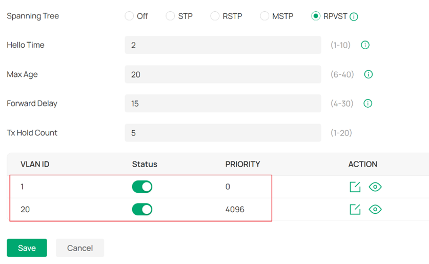
Configure another Omada switch with mostly the same settings. The differences are:
- Priority of VLAN 1 to 0
- Priority of VLAN 20 to 4096
Note: When other Omada switches in the network are running STP/RSTP/MSTP, ensure that RPVST-enabled Omada switches use a higher priority for VLAN 1, which means numerically lower Priority value.
Step 3. Enable RPVST for ports.
The configuration path is the same as STP. Please refer to Step 2 under Configure STP on Omada Controller.
You can enable Instance/VLAN Priority to configure individual port Priority and Path Cost values for each VLAN.
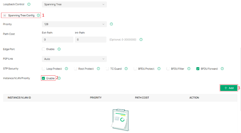
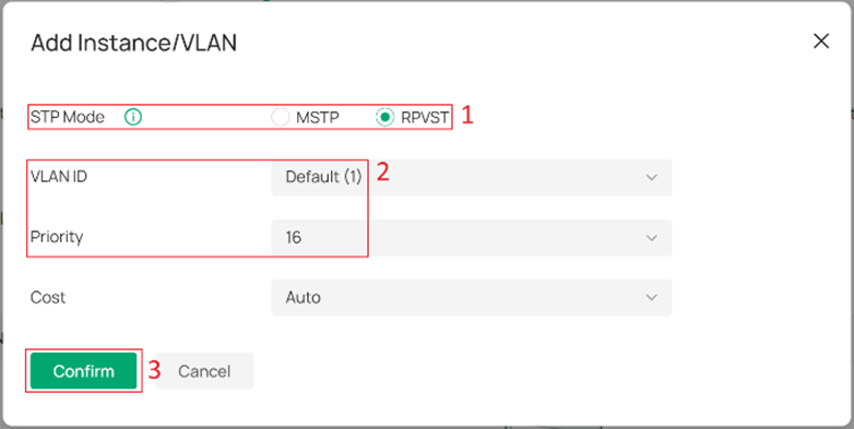
Note: If Instance/VLAN Priority is not enabled, or if only some VLANs are configured with individual port Priority and Path Cost settings, the remaining VLANs will use the default values.
Step 4. Check Operation Status
You can click the eye icon in the Action column for each VLAN entry to view the operation status of each VLAN instance on the RPVST configuration page.
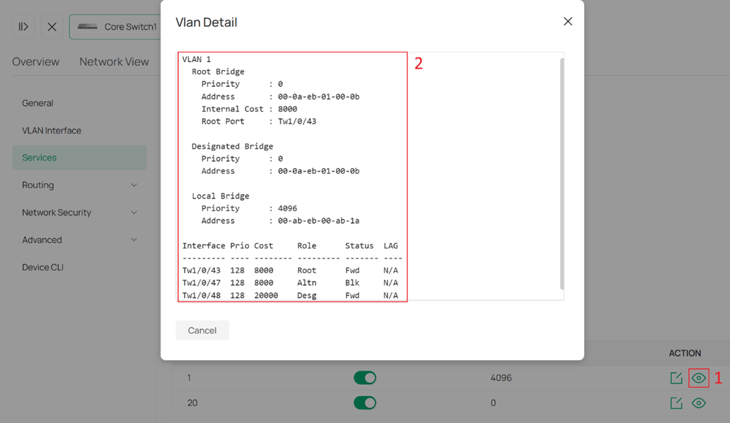
Note: Only VLANs with enabled Status support viewing operation status via the eye icon. When disabled Status, the VLAN is mapped to instance 0. You can use the same method as STP to view the operation status of the instance 0. Please refer to Step 3 under Configure STP on Omada Controller. For the behavior of instance 0, please refer to QA.
Conclusion
By following the steps in the Configuration section, Spanning Tree can be configured to prevent loops in the network.
Get to know more details of each function and configuration please go to Download Center to download the manual of your product.
QA
Q1: How does RPVST work?
A1: RPVST is similar to MSTP in that it maps VLANs to instances and calculates a spanning tree for each instance. However, unlike MSTP, instance mapping in RPVST is performed automatically.
When switching modes or re-enabling RPVST, VLANs are mapped to available instances in ascending order of VLAN ID, until the maximum number of instances is reached. Any remaining VLANs will be mapped to instance 0.
When a new VLAN is created, if there are available instances, it will be mapped to the first available instance. If no instances are available, it will be mapped to instance 0. Once a VLAN is mapped to instance 0, the mapping will not change.
Q2: How does priority take effect for VLANs that exceed the instance limit in RPVST?
A2: For VLANs that exceed the instance limit, the configured priority does not take effect. These VLANs run on instance 0, whose priority is always 32768.
