Contents
This article introduces how to configure LLDP and LLDP-MED on Omada Switches via the Omada Controller.
- Omada Software/Hardware/Cloud-Based Controller V5.0 and above
- Omada Smart/L2+/L3 Switches
Link Layer Discovery Protocol (LLDP) provides a standard link layer discovery mechanism, allowing devices from different manufacturers to discover and exchange their respective system and configuration information in the network. The LLDP-MED TLVs (Type-Length-Values) offer many advanced features for VoIP, including basic configuration, network policy configuration, address information, and directory management, meeting the requirements of different VoIP device manufacturers in terms of high return on investment, easy deployment, and easy management. It also solves the problems in deploying voice devices in Ethernet networks, providing convenience for VoIP device manufacturers, sellers, and users.
A typical application scenario for LLDP-MED is as follows. LLDP-MED allows the switch to send its Auto-VoIP information to IP phones for automatic configuration. In this example, LLDP-MED needs to be enabled on port 1/0/1 of the switch.

Here are the steps to configure LLDP-MED on the Omada switch via the Omada Controller:
- Configure a Voice VLAN.
- Create a Switch Port Profile.
- Assign the Port Profile to the switch ports where you want to enable LLDP-MED.
Note: LLDP is enabled by default and cannot be disabled on the Omada switch managed by the Omada Controller. LLDP-MED is enabled automatically when creating Switch Port Profile.
Step 1. Log in to the Omada Controller. Go to Settings > Wired Networks > LAN > Networks and click Create New LAN.

Step 2. Create a 802.1Q VLAN2 as the Voice VLAN and click Save to save the settings.

Step 3. Go to Settings > Wired Networks > LAN > Switch Profiles and click Create New Port Profile.

Step 4. Set the Voice VLAN as Tagged Networks and Voice Network. LLDP-MED is enabled by default. Click Save.

Step 5. Go to Devices, click the switch to open the Properties window, and go to the Port tab. Click the Edit icon of Port 1.

Step 6. Bind the Voice-Data-Network profile to Port 1. If LLDP-MED needs to be enabled on other ports, bind the same profile to the corresponding ports.

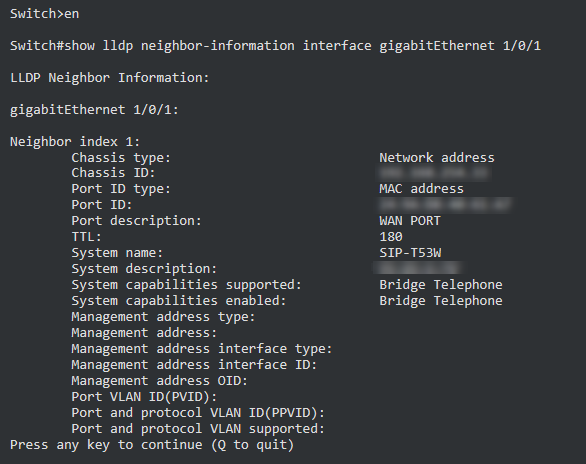
Step 1. Go to Tools > Terminal. Select Switch for Device Type and choose the switch with LLDP-MED enabled in the pop-up window of Sources. Click Open Terminal.

Step 2. Enter the following commands to view the LLDP neighbor. The result shows that the LLDP neighbor between the IP phone and the switch has been established.
en
show lldp neighbor-information interface gigabitEthernet 1/0/1

You have successfully configure LLDP and LLDP-MED.
Get to know more details of each function and configuration please go to Download Center to download the manual of your product.


