About This Guide
This document offers startup guidance for an NVR, including a detailed hardware overview and quick references for hardware installation and software configuration.
Related Documentation
The Quick Installation Guide can be found in the product packaging and on the Product Support page: https://support.omadanetworks.com/product/
The latest Regulatory Compliance document, User Guide, Datasheet can be found on the Documents page: https://support.omadanetworks.com/document/
More Resources
| Main Site | https://www.omadanetworks.com/ |
|---|---|
| Video Center | https://support.omadanetworks.com/video/ |
| Documents | https://support.omadanetworks.com/document/ |
| Product Support | https://support.omadanetworks.com/product/ |
| Technical Support | https://support.omadanetworks.com/contact-support/ |
Hard Overview
This chapter provides a detailed hardware overview of the NVR.
Front Panel
The figure is for demonstration purposes only. Your device may differ in appearance from the depicted.
Note: A 3.5-inch HDD is pre-installed in the NVR for recording and playback. You can replace the HDD if necessary. It is recommended to use a surveillance-level HDD for optimal performance. Before installation, ensure the network video recorder (NVR) is powered off.
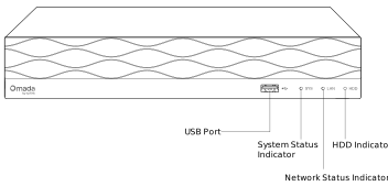
· Omada NVR16-8P-2T/Omada NVR16-8P-4T
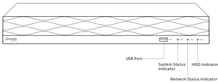
· Omada NVR24-16P-4T
· LED Status
| Indicator | Name | Status | Description |
|---|---|---|---|
| SYS | System Status Indicator | On | System is running normally. |
| Off | System is running abnormally/System is off (probably not powered on). | ||
| LAN | Network Status Indicator | On | Network is working properly. |
| Flashing | Data is being transmitted or received. | ||
| Off | The network is malfunctioning/ Ethernet cable not plugged in. |
||
| HDD | Hard Disk Drive Indicator | On | The HDD is functioning properly. |
| Off | No HDD or the HDD is malfunctioning. |
Back Panel
The figure is for demonstration purposes only. Your device may differ in appearance from the depicted.
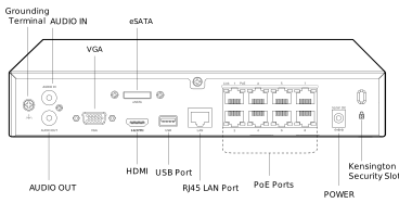
· Omada NVR16-8P-2T/Omada NVR16-8P-4T
· Omada NVR24-16P-4T
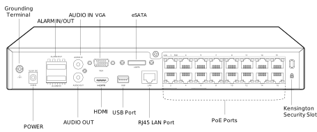
· Interfaces
| Interface | Description |
|---|---|
| AUDIO IN / AUDIO OUT | Connector for audio input and output. |
| VGA | Connect your monitor to this port if it uses a VGA connection. |
| HDMI | Connect your monitor to this port if it uses an HDMI connection. |
| eSATA | Connect to an external hard drive for expandable storage. |
| USB (Front Panel) | USB 2.0 port for connecting external devices such as USB mouse and USB keyboard. |
| USB (Back Panel) |
USB 3.0 port for connecting external storage devices and enabling rapid exports of footage. |
| LAN | RJ45 10/100/1000 Mbps self-adaptive Ethernet port. Connect to an Ethernet device (eg. router or switch). |
| PoE | Connect to the device with a bandwidth of 10/100 Mbps. The port can also provide power for the cameras. |
| POWER | Connector for power input. |
| ALARM IN / ALARM OUT (For NKN224/NVR224P-4T) | Connect to alarm input/output devices using the provided terminal blocks. |
| Grounding Terminal | The device is equipped with a lightning protection mechanism. |
| Kensington Security Slot | Secure the lock (not provided) into the security slot to prevent the device from being stolen. |
Hard Drive Installation
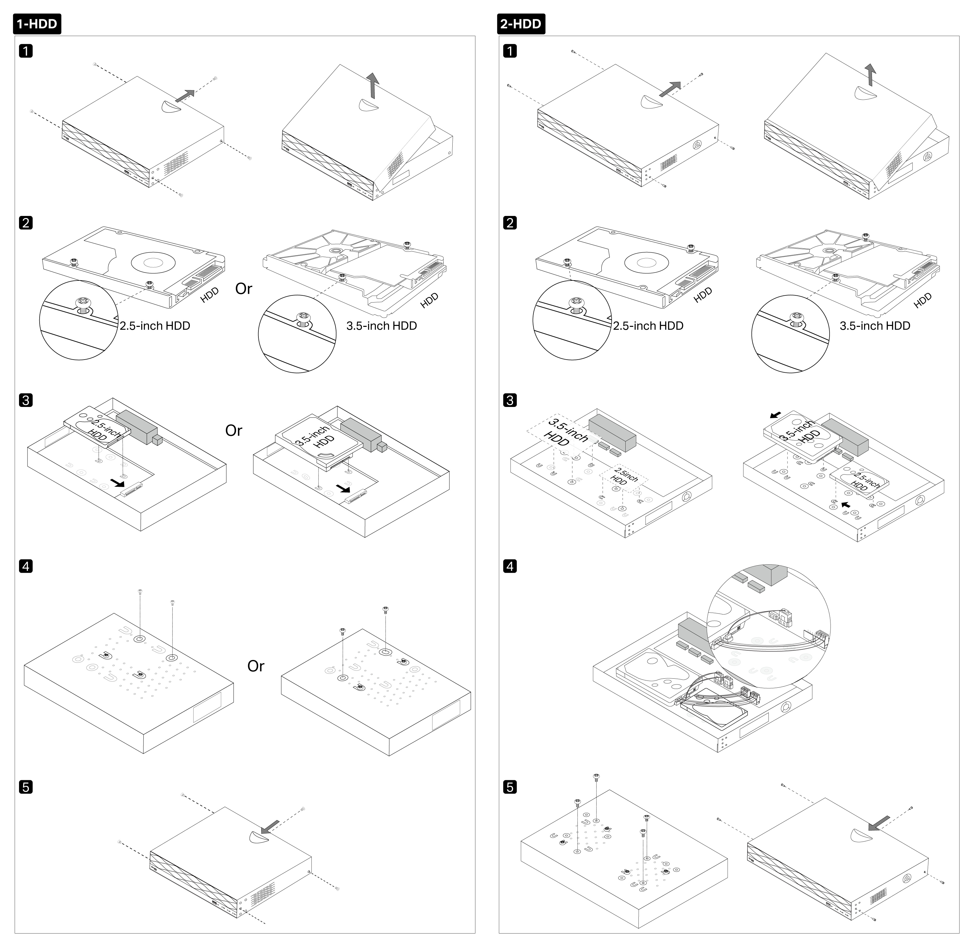
A 3.5-inch HDD is pre-installed in the NVR for recording and playback. You can replace the HDD if necessary. It is recommended to use a surveillance-level HDD for optimal performance. Before installation, ensure the network video recorder (NVR) is powered off.
Caution: To prevent the hard drive from falling during disassembly, support the hard drive from the bottom while loosening the screws.
For videos on how to install/replace the hard drive for NVR, visit https://support.omadanetworks.com/video/?category=omada-security-camera to search for your product.
For instructions on how to select an appropriate hard drive, see https://www.omadanetworks.com/support/faq/4518/.
Connect Alarm Devices (Optional)
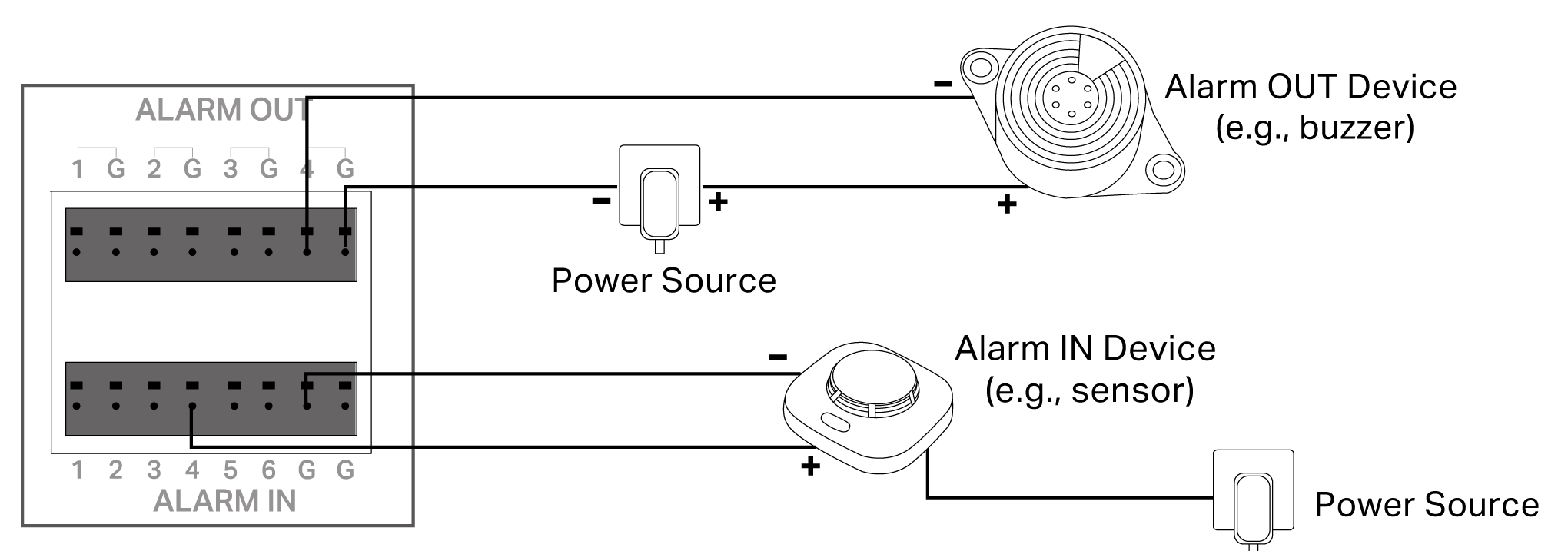
This is only for certain models. Refer to https://www.omadanetworks.com/support/faq/4455/ for detailed instructions.
Configuration
Follow the hardware connection steps below to connect devices, then refer to the product manual for more details on the support website.
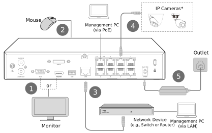
1. Follow the steps on the left to connect the hardware, and connect the cameras and NVR to the network.
2. Download and launch the Omada Guard app, and then follow the on-screen instructions to scan the device key QR code printed on the NVR or box to initialize the NVR.

The NVR can also be configured and managed via the GUI and web UI. The default web login address is https://192.168.0.240 (via LAN) or https://192.168.253.1 (via PoE). Refer to the product manual for more details on the support website.
· Via NVR GUI
Refer to https://www.omadanetworks.com/support/faq/4454/ for detailed instructions.
· Via Web UI
The default web login address is https://192.168.0.240 (via LAN) or https://192.168.253.1 (via PoE).
More Configurations
For more configurations, refer to the User Guides on the Documents page: https://support.omadanetworks.com/document/
* How to mount the camera
Refer to the camera's installation guide to mount the camera as needed.
Appendix
How to Reset Your NVR
Option 1: Reset via Menu
1. Open your monitor, click the menu button on the upper left corner to open the menu. Click System.
2. Go to General Settings > System Configuration > Settings Management.
3. Click Reset to restore your NVR to its factory settings.
Option 2: Reset via Physical Button
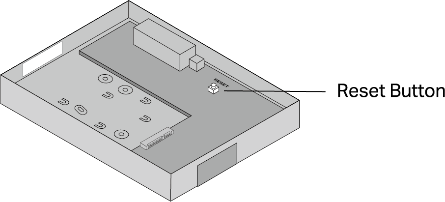
1. Remove the NVR’s cover and find the Reset button inside the NVR.
2. Press and hold the Reset button for at least 5 seconds, and the buzzer on the NVR will beep. The NVR will be restored to its factory settings.