


Contents
Objective
This guide introduces the use of the Cable Test feature available on Omada Central for troubleshooting cable faults.
Requirements
- Omada Central
- Omada Switches
Introduction
The Cable Test function provides network administrators with a straightforward yet powerful tool for diagnosing and testing network cable connection issues, facilitating the quick identification and location of network connectivity faults and enhancing network maintenance efficiency.
Cable Test Configuration
The Cable Test can identify cable failures and locate the point of failure, which helps resolve cable faults.
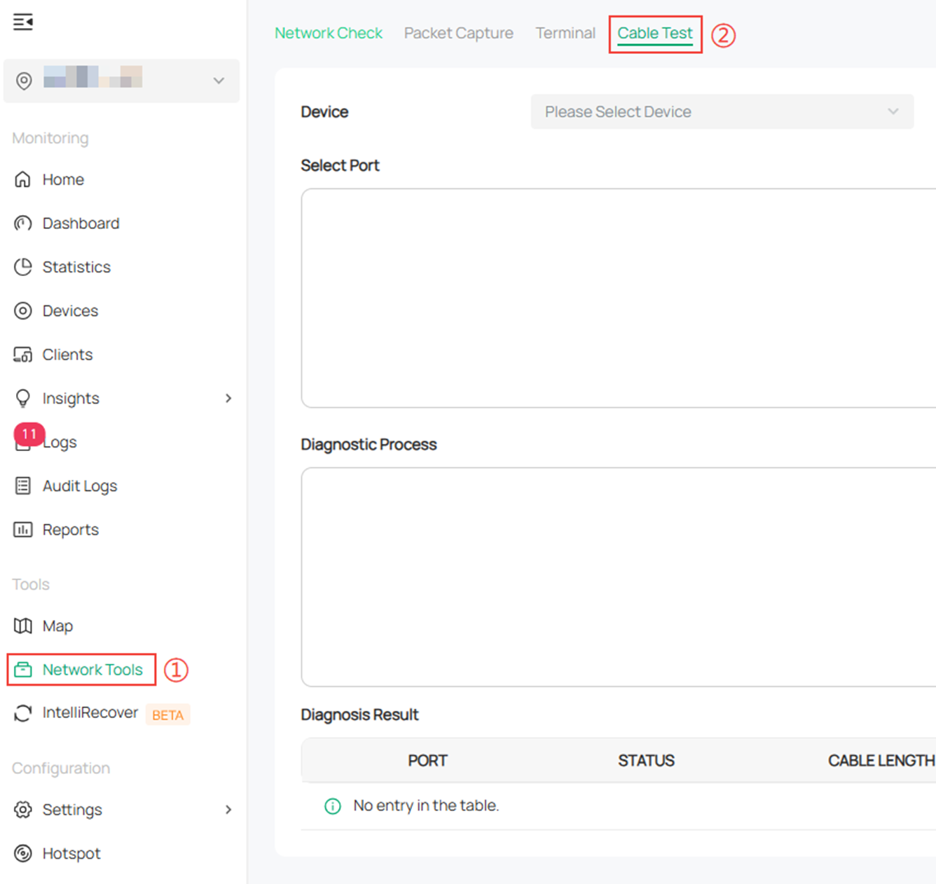
Step 1: Log in to Omada Central using a web browser. Under Site View, navigate to Network Tools > Cable Test.
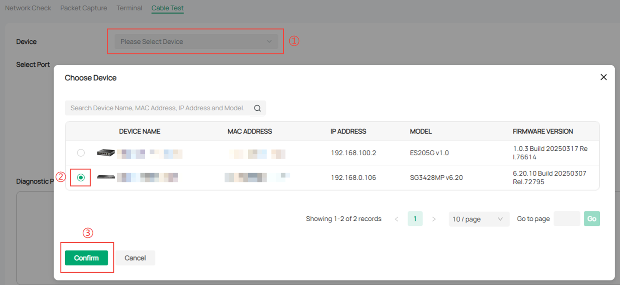
Step 2. Click on Select Device, choose the device that will undergo the Cable Test, and then click Confirm. Only Omada Switches in the Connected state can be selected here.
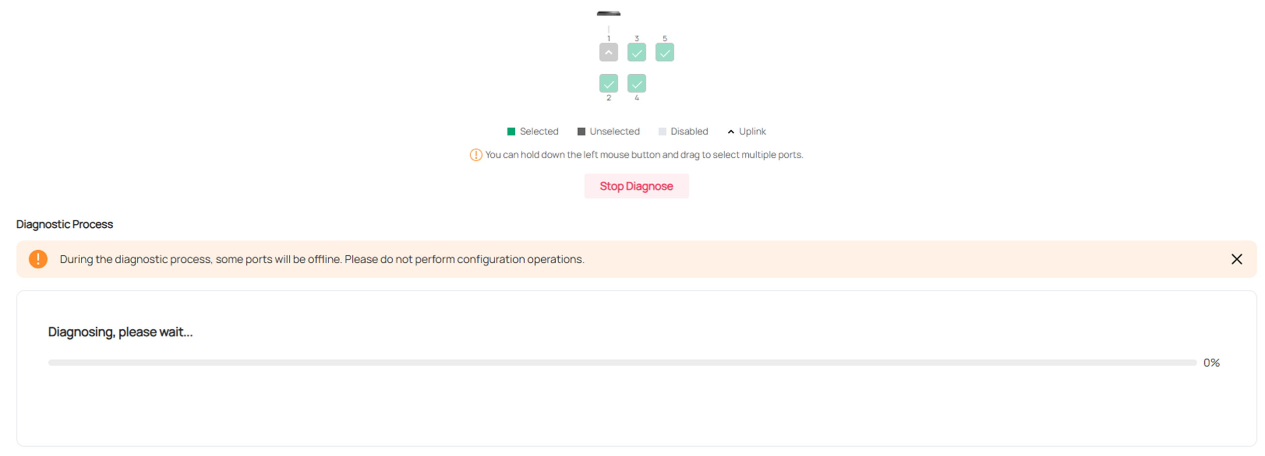
Step 3. Select the port to be tested and click Diagnose to initiate the test.

Step 4. During the test, progress will be shown, and you can stop the test by clicking "Stop Diagnose."
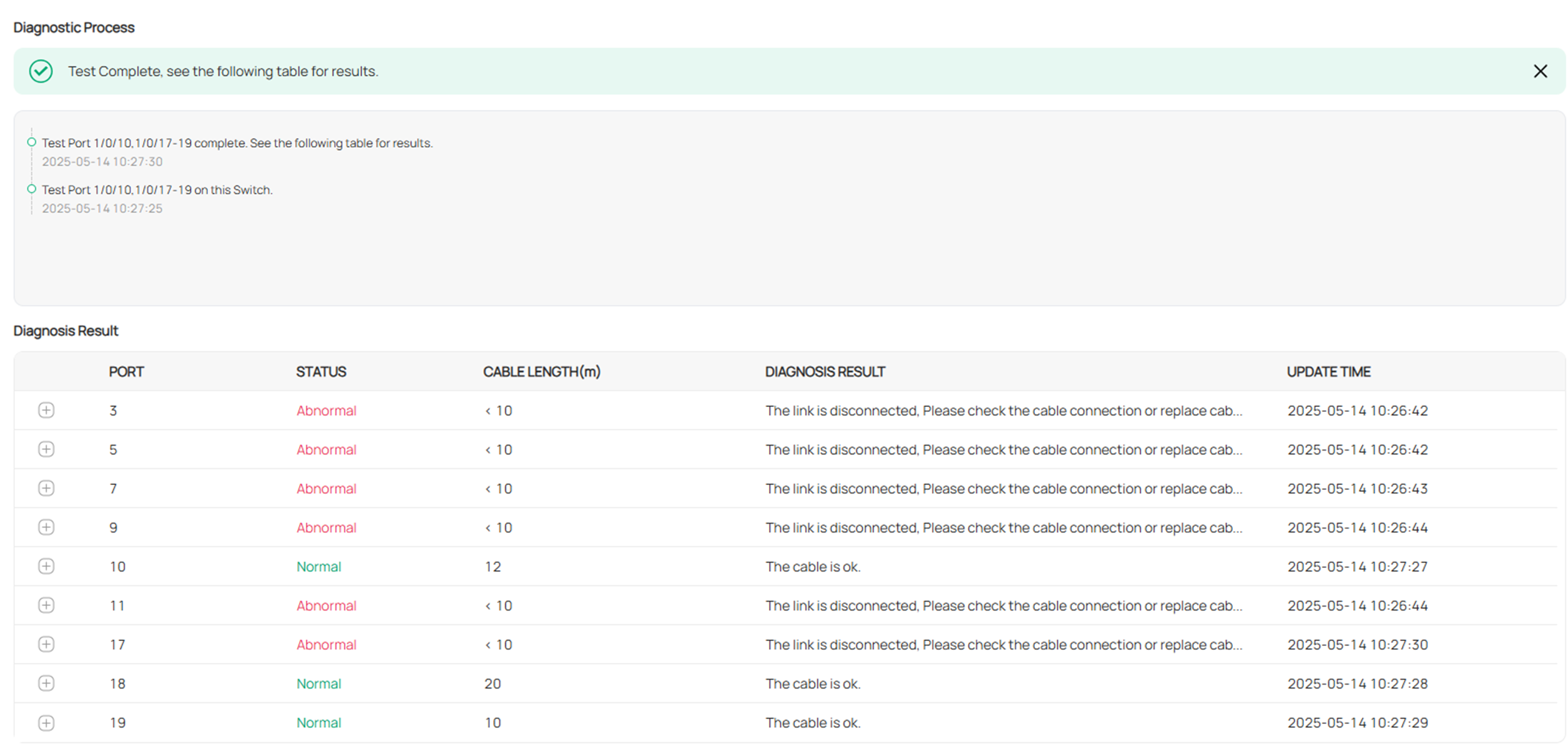
Step 5. After the test is complete, view the results in the Diagnosis Result section. The tested port number and the test results will be displayed in order. You can also click the expand icon on the left side of the port number to see more detailed results.

Detailed Results Explanation
|
Item |
Explanation |
|
Pair 1/2/3/4 |
Represents the four pairs of wires in the cable. |
|
Cable Length |
When a fault occurs, it indicates the distance from the interface to the fault location. |
|
When there is no fault, it indicates the actual length of the cable. |
|
Status |
Detialed Status |
|
Normal |
Normal: Indicates that the wire pair (PAIR) is properly terminated. |
|
Abnormal |
Open: Indicates that the wire pair is open-circuited. |
|
Short: Indicates that the wire pair is short-circuited. |
|
|
Crosstalk: Indicates that there is crosstalk (interference) between wire pairs. |
|
|
Not Support: Indicates that the port does not support this function. |
|
|
Unknown Error: Indicates an unknown fault. |
Note:
1. Only electrical interfaces or combo interfaces operating in electrical mode support the cable detection function.
2. Executing the cable test may temporarily impact the regular operation of the interface. It is recommended to use it solely when troubleshooting cable faults.
3. The cable test is supported when the interface is operating at 1000 Mbit/s in auto-negotiation mode. Some switches support the cable test at 100 Mbit/s in auto-negotiation mode, but only for wire pairs 1 and 2.
4. For certain switches, the cable length cannot be measured if the peer device is powered off.
5. When the cable status is abnormal, the displayed length indicates the distance from the local interface to the location of the fault.
6. The test results may not be accurate for network cables manufactured by all vendors and are for reference only.
7. The device does not support VCT detection on multiple interfaces simultaneously.
Conclusion
The above is an introduction to the Cable Test on Omada Central.
Get to know more details of each function and configuration please go to Download Center to download the manual of your product.
