


About This Guide
This User Guide provides information for using and managing cameras via a web browser. It explains functions of cameras and shows you how to configure them.
Conventions
When using this guide, notice that:
■ Features available in cameras may vary due to your region, device model, and firmware version. All images, steps, and descriptions in this guide are for demonstration purposes only and may not reflect your actual experience.
■ The information in this document is subject to change without notice. Every effort has been made in the preparation of this document to ensure accuracy of the contents, but all statements, information, and recommendations in this document do not constitute the warranty of any kind, express or implied. Users must take full responsibility for their application of any products.
More Information
■ For technical support, the latest version of the User Guide and other information, please visit https://support.omadanetworks.com/.
■ The Quick Installation Guide can be found where you find this guide or inside the package of the product.
Login
This chapter guides you on how to log in to the web UI of the camera.
After the cameras are added to network, multiple methods are provided for you to monitor and manage cameras. You can manage and monitor the cameras remotely via the Omada Guard app, and you can also directly monitor and manage your camera via a web browser. Check the support page of the product for more manuals at https://support.omadanetworks.com/.
Connect the Camera to Network
The camera works with an NVR for easier batch access and management. You can add cameras to network via an NVR.
1. Connect your cameras to the same network as your NVR (as shown below).
2. Power on your cameras.
3. Follow the NVR manual to add and activate your cameras.
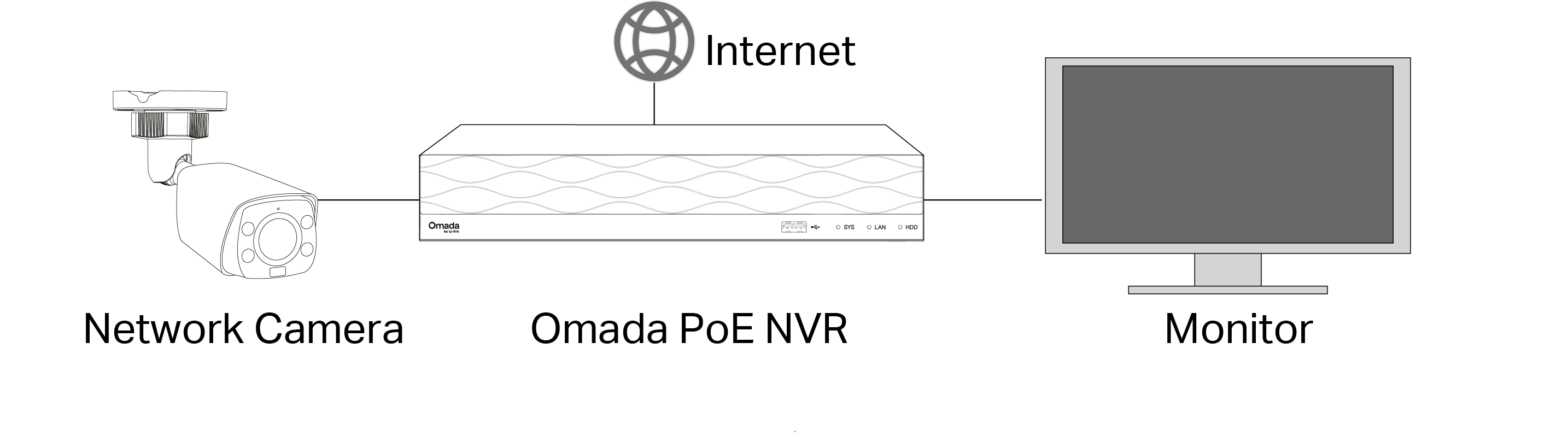
Note: You can follow the Quick Start Guide included in the package to mount and add cameras to your network.
Log in to the Web Interface
With an intuitive user interface, it is easy to configure and manage the camera via a web browser. Follow the steps below to log in to the web UI of the camera for the first time.
1. Find the camera’s IP address on your router’s client page.
2. On your local computer, open a web browser and enter https://camera’s IP address
(https://192.168.0.60 by default).
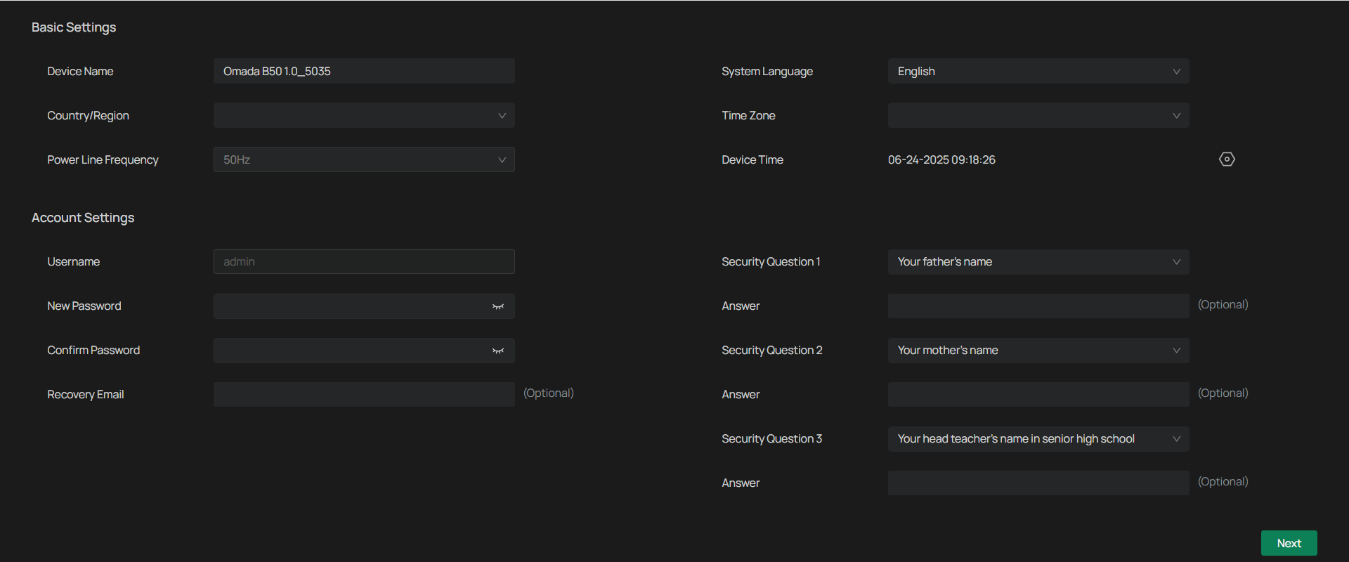
3. Select your Country/Region and Time Zone.
4. Set a password to activate the camera.
Now, you can log in to the camera using the password set here.
5. Set Password Protection. If you forget password, you can reset it with your security questions or recovery email.
Select your security questions and input your answer.
Enter your email address to receive the verification code during the recovery operation process.
6. Click Next.
Note:
1. For future logins, use the default username admin and the password you set for this camera.
2. If you forgot the password, click Forgot password? and follow the web instructions to reset the
password.
Live View and Playback
With your camera’s Live View and Playback features, you can access the camera’s interface, view real-time footage, adjust display settings, and navigate essential controls. Additionally, you’ll discover how to review recorded video and manage playback tools for efficient monitoring and security management.
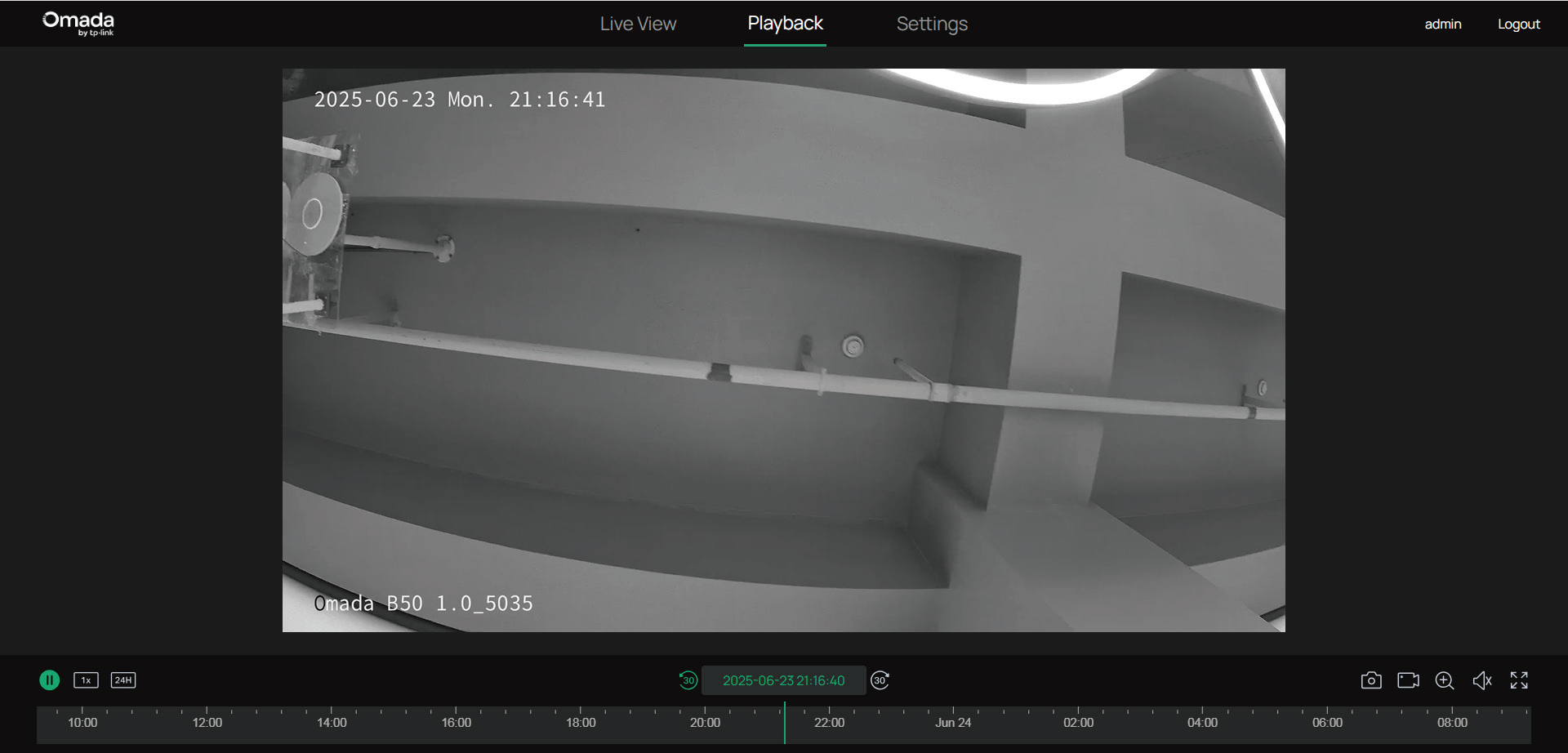
Playback
The Playback feature allows you to review previously recorded footage directly from the camera interface. With a SIM card inserted, event-based recordings can be accessed for review. To configure which events trigger recording, refer to the Events chapter.
| Icon | Explanation |
|---|---|
 |
Hit to pause or resume the playback. |
 |
Speed Playback: Increase the speed for fast-forward or decrease for slow-motion review. |
 |
Time Span: Click to change the period of time between 10 minutes to 24 hours. |
 |
Screenshot: Take manual snapshots for the live view window. |
 |
Record: Click once to begin recording, and click again to end it; the recordings will be automatically saved to your designated path. |
 |
Digital Zoom: Zoom in to get a closer look at the image for finer details; zoom out for a wider panoramic image. |
 |
Volume: (Only for certain cameras) Click to adjust the volume of the speaker. |
 |
Full Screen: Click to change the live view image to the entire screen. |
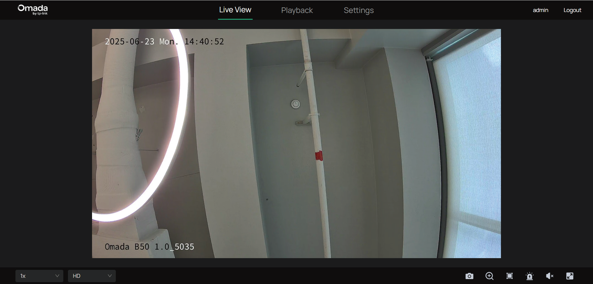
Live View
This section introduces the live view parameters and function icons.
1. Find the camera’s IP address on your gateway’s client page.
2. On your local computer, open a web browser and enter https://camera’s IP address (https://192.168.0.60 by default).
3. Log in with the default username admin and the password you set for this camera.
4. You can view the live video on the Live View page.
Note: This is for demonstration only.
| Icon | Explanation |
|---|---|
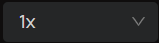 |
Select the aspect ratio. 1x refers to the original window size. 4:3 refers to 4:3 window size. 16:9 refers to 16:9 window size. 100% refers to self-adaptive window size. |
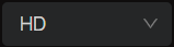 |
Click to change the resolution type. HD stands for high definition. SD stands for standard definition. HD offers a higher pixel count and therefore a sharper, more detailed image than SD. |
 |
Screenshot: Click to capture a screenshot. |
 |
Digital Zoom: Click to see more details of any area in the image. |
 |
Smart Frame: After enabling the Smart Frame feature under Events, use this switch to choose whether to display detection frames on the current web preview screen. |
 |
Alarm: (Only for certain cameras) Click to trigger the sound alarm and lasts about 10 seconds. |
 |
Volume: (Only for certain cameras) Click to adjust the volume of the speaker. |
 |
Full Screen: Click to change the live view image to the entire screen. |
 |
Zoom Out: (Only for certain cameras) Click to zoom out the live image. |
 |
Zoom In: (Only for certain cameras) Click to zoom in the live image. |
 |
Focus -: (Only for certain cameras) Shorten the focal length. |
 |
Focus +: (Only for certain cameras) Increase the focal length. |
 |
Lens Initialization: (Only for the camera with motorized lens) Click to reset lens when long time zoom or focus results in blurred image. |
 |
Auxiliary Focus: (Only for the camera with motorized lens) Click to focus automatically. |
View Device Information
This chapter introduces how to check the system logs and view your device information on the web UI.
View System Logs
The camera uses logs to record, classify, and manage system and device messages. You can search, view, and export the logs.
1. Go to Settings > Information > System Log > System Log.
2. Specify search conditions, including the Start Time, End Time, and Log Type, and click Search. The filtered logs that match the search conditions will appear in the table.
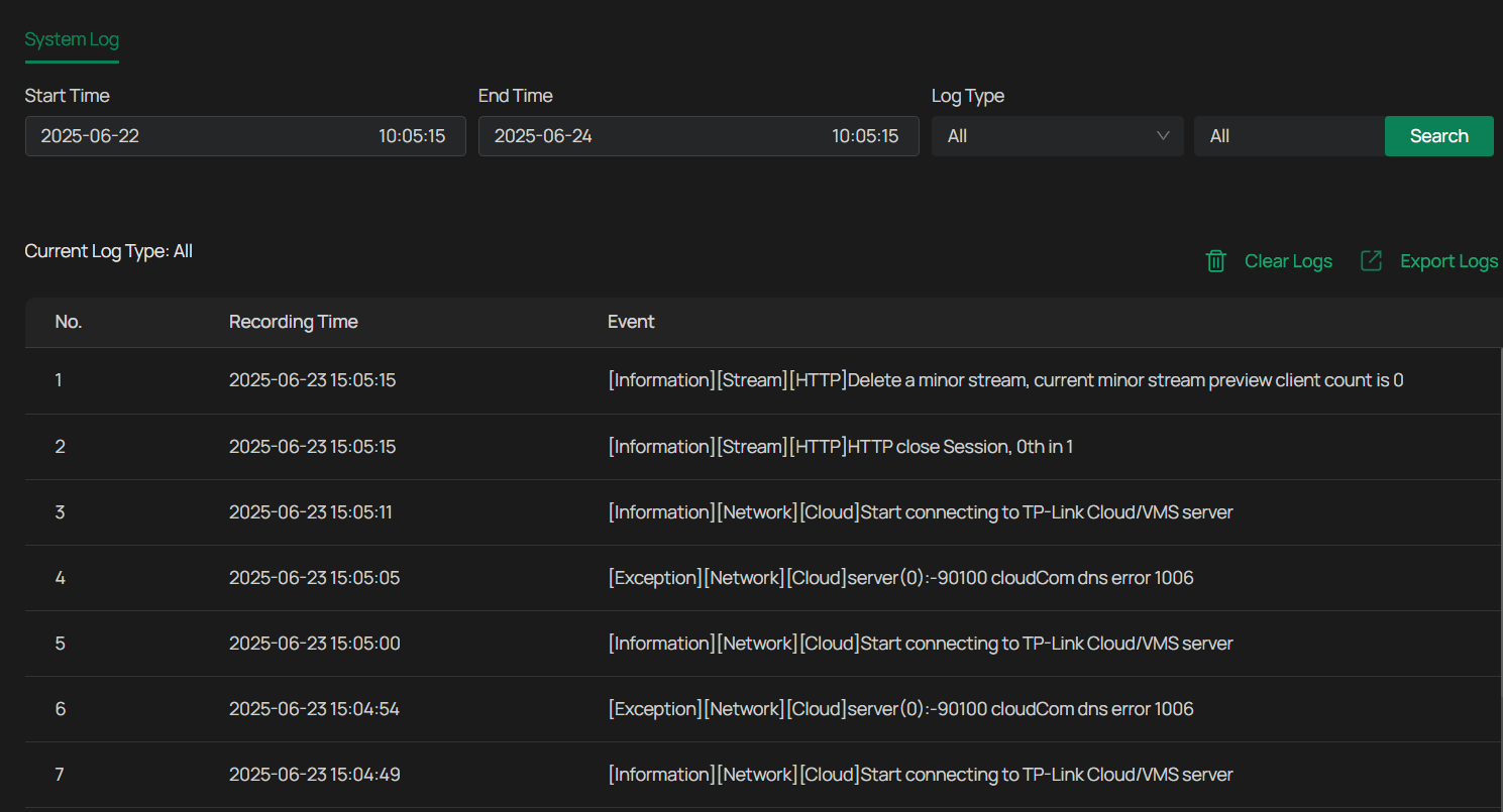
| Parameter | Explanation |
|---|---|
| Start/End Time | Specify a time range to filter the logs based on the recording time. |
| Log Type | Select a type from the drop-down list to filter the logs. All: All types of logs. Alarm: Alarms triggered by events, such as tampering, line crossing, and area intrusion. Exception: Abnormal events that may influence the camera’s functions, such as video signal loss and hard drive errors. Operation: Actions that take place on the camera, such as login and upgrade. Information: Informational messages, such as device information. |
| Clear Logs | Click to delete all logs. |
| Export Logs | Click to save log files to your computer. |
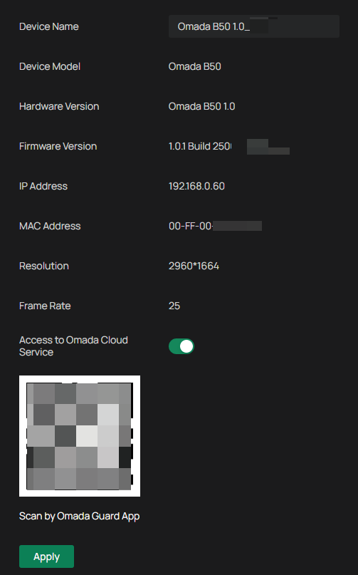
View Device Information
You can view basic information about the camera, including device model, firmware version, network information, stream information, and device QR code.
Go to Settings > Information > Device Information > Device Information.
Change Camera Settings
This chapter introduces how to change the camera display settings and camera streams settings.
Camera Display Settings
You can adjust image features according to your needs.
Privacy Mask
Privacy Mask conceals parts of the image from view and protects your privacy. The area you set cannot be recorded and monitored.
Follow the steps below to configure Privacy Mask.
1. Go to Settings > Camera > Display > Privacy Mask.
2. Enable Privacy Mask. Draw the privacy area on the preview screen (the blue square in the picture below). Drag the area to adjust its size and location. For Mask Type, you may choose Solid Black or Mosaic, which determines the display effect of the area.
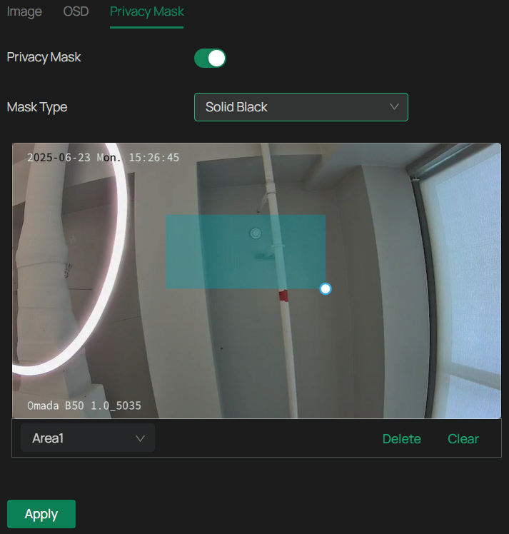
3. To remove a certain privacy area, select it and click Delete.
4. To remove all privacy areas, click Clear.
5. Click Add to automatically add an area on the center of the screen.
6. Click Apply.
OSD Settings
You can configure OSD (On Screen Display) to edit the information displayed in Live View and recordings.
Follow the steps below to configure OSD settings.
Go to Settings > Camera > Display > OSD.
Configure the following parameters, and click Apply.
Note: Tap the Position icon at the bottom of the live view to adjust where items appear on the screen.

| Parameter | Explanation |
|---|---|
| Display Date | Check to display the date on the image. |
| Display Day of Week | Check to display the week on the image. |
| Display Channel Name | Check to display the channel name on the image. You can also check Custom and specify a text to display. |
| Display Effect | Set the display effect of the image. |
| Font Size | Set the font size. |
| Font Color | Set the font color. |
| Restore | Click to restore to factory default settings. |
Image Settings
1. Go to Settings > Camera > Display > Image.
2. Configure the following parameters.
| Parameter | Explanation |
|---|---|
| Rotation | Choose to turn the live view image by 0, 90 or 270 degrees on your display. When you select Off, the image displays normally. |
| Mirror | Select the mirror mode as needed. When you select Off, the image displays normally. By choosing Left-Right, you mirror the image on the vertical axis. By choosing Up-Down, you flip the image on the horizontal axis. By choosing Central, you rotate the image by 180 degrees around its center. |
| General Settings | |
| Power Line Frequency | Set the Power line frequency consistent with local utility settings to eliminate image flickering associated with fluorescent lights. |
| Night Vision Mode | Human/Vehicle Triggered Full-Color: The camera switches to the full-color mode once it detects a person or vehicle. Auto Color: The camera turns on or off the white supplement light according to the light condition of the environment. Auto IR: The camera turns on or off the IR supplement light according to the light condition of the environment. White LED Always On: White supplement light is on. IR Always On: IR supplement light is on. Off: Supplement light is off. Custom: Select it to configure Day/Night Switch and Illuminator. |
| Switch Day and Night Settings | |
| Day/Night Profile |
Select a method to switch the image settings of day and night. |
| Image Scene | Select a display mode — Realistic, Balanced, Vivid, or Custom. The settings below will automatically adjust based on your selection. |
| Image Adjustment | |
| Brightness | Increasing the value will lighten the image. |
| Contrast | Increasing the value will increase the difference between the brighter and darker parts. |
| Saturation | Increasing the value will enrich the color of the image. |
| Sharpness | Increasing the value will sharpen the image. |
| Exposure Settings | |
| Exposure | Select the exposure mode as needed. Auto: The camera adjusts the exposure automatically. Manual: The image exposure is fixed. If you select Manual, adjust the slide bar of Gain to specify its value, and select a shutter speed. Higher gain and slower shutter speed result in brighter images. Anti-flicker: This function minimizes influences caused by flickering. |
| Backlight Settings | |
| BLC Area | BLC (Backlight Compensation) optimizes the camera to increase light exposure for darkened areas and helps you to see details more clearly. Select an area to compensate light. If you select Custom, draw a blue rectangle on the live view image as the BLC area. |
| WDR | WDR (Wide Dynamic Range) can improve the image quality under high-contrast lighting conditions where both dimly and brightly lit areas are present in the field of view. If you select On, the camera balances the light of the brightest and darkest areas automatically. You may set the gain value, or the sensor’s sensitivity, manually. |
| HLC | HLC (Highlight compensation) can compensate for brighter parts of your image, maintaining detail in brighter parts of the image that would otherwise be blown out. |
| White Balance | |
| White Balance | White balance is a process of removing unrealistic color casts, so that objects which appear white in person are rendered white in the image. Auto: The camera adjusts the color temperature automatically. Locked: The camera keeps the current color settings all the time. Daylight/Natural Light/Incandescent/Warm Light: The camera adjusts the color temperature to remove the color casts caused by the corresponding light. Custom: Drag the slide bar to configure the color temperature, and the camera keeps the settings all the time. You may specify the red/blue gain values separately. The higher the value is, the more intense the red/blue color is. |
| Image Enhancement | |
| Prevent IR Overexposure | Select the standard mode or enhanced mode or manually adjust the brightness of image. Standard Mode: In this mode, the brightness of the infrared light will be automatically adjusted to prevent overexposure. The brighter the environment, the dimmer the infrared supplement light. Enhanced Mode: This mode intensifies its protection against overexposure, by darkening the bright areas of the image. Manual: Manually adjust the brightness of image by setting the values for overexposure level, space DNR level, and time DNR level. |
| Over-exposure Level | Adjust the level of exposure compensation to reduce glare in bright areas. Drag the slider to set a value between 0 and 100. Higher values increase compensation in overexposed regions. |
| Space DNR Level | Space Digital Noise Reduction Level controls the reduction of static noise in individual frames. Drag the slider to set a value between 0 and 100. Higher values apply stronger noise reduction, which may smooth image details. |
| Time DNR Level | Time Digital Noise Reduction Level reduces noise across frames to improve image clarity in low-light conditions. Drag the slider to set a value between 0 and 100. Higher values result in more aggressive noise reduction over time. |
| Illuminator Settings | |
| Illuminator Switch |
Controls the behavior of the camera’s built-in illuminator. Choose from the following modes: |
| Illuminator Type | Infrared Lighting: The infrared supplement light is on all the time. Human/Vehicle Trigger Full-Color: The camera turns on the full-color mode once it detects a person or vehicle. White Light Illuminator: The white supplement light is on all the time. With this selected, you may customize White Light Intensity parameters. |
| Sensitivity | Decide the ambient light intensity that can trigger the switch of the white light. The lower the value is, the easier it is to trigger the white light. |
| Delayed Switch | Decide how long the camera waits to turn on or off the white light when the ambient light reaches the threshold to trigger the switch. |
| White Light Intensity | Smart White Light-Standard: The camera illuminates a white light when detecting a target. Smart White Light-Soft: The camera illuminates a warmer white light when detecting a target. Manual: Drag the slide bar to manually adjust the intensity of the white light. The light gets brighter when the value increases. |
| Always Full-Color at Live View | The camera will automatically turn on Full-Color Night Vision when you stream Live Video. |
| Restore | Click to restore to factory default settings. |
Camera Stream Settings
In Stream Settings, you can configure video stream levels, change the audio output settings and ROI (Region of interest) level.
Video stream levels decide the video quality in Live View and recording, and you can adjust the video quality of certain area by specifying the ROI level.
Video Settings
Follow the steps below to configure video settings.
1. Go to Settings > Camera > Stream > Video.
2. Configure the following parameters, and click Apply.
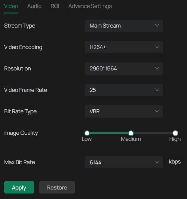
| Parameter | Explanation |
|---|---|
| Stream Type | Main Stream is the primary video feed used for recording and provides the highest video quality. It has higher definition and higher bandwidth than substream. Substream is a secondary video feed that is used mainly for remote viewing from computers from outside the network. |
| Video Encoding | Video encoding format determines how video data is compressed for transmission and storage. H.264: Delivers good image quality at moderate file sizes, compatible with nearly all video management systems and devices. H.264+: Further reduces bandwidth and storage requirements, especially in static scenes, without significantly lowering image quality. H.265: Provides similar video quality as H.264 but at roughly 50% lower bit rates, making it ideal for saving bandwidth and storage, especially for high-resolution video like 4K. H.265+: Achieves even greater bandwidth and storage savings by intelligently compressing static areas of the video while preserving detail in moving objects. Note: H.265 and H.265+ require more processing power for decoding. Ensure your hardware or software systems support the chosen codec. |
| Resolution | The screen displays images more clearly when the resolution increases. |
| Video Frame Rate | The video is more fluent when the rate increases. |
| Bite Rate Type | The Max Bit Rate setting controls how much data the camera uses to encode video, which directly affects image quality and network bandwidth usage. You can choose between two modes: CBR (Constant Bit Rate): The camera maintains a fixed bit rate regardless of the scene’s complexity. VBR (Variable Bit Rate): The bit rate adjusts dynamically based on scene complexity. |
| Image Quality | When VBR is selected as the Bit Rate Type, set the video quality as high, medium, or low. The higher the quality level, the more bandwidth the camera may use during complex scenes. |
| Max Bit Rate | Specify the upper limit of data the camera can use per second when encoding video. Higher bit rates allow for clearer, more detailed images and consume more network bandwidth. |
| Restore | Click to restore to factory default settings. |
Audio Settings (Only for some models)
Follow the steps below to configure video settings.
1. Go to Settings > Camera > Stream > Audio.
2. Configure the following parameters, and click Apply.
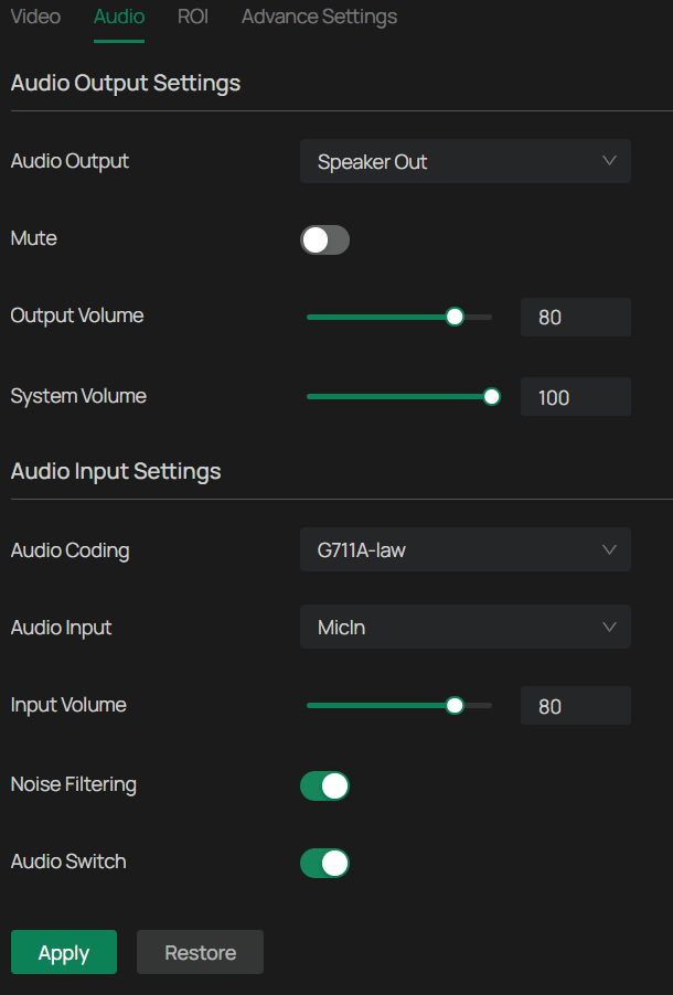
| Parameter | Explanation |
|---|---|
| Audio Output | Select from the drop-down menu how the camera delivers sound. |
| Mute | Toggle to mute the speaker of the camera. |
| Output Volume | Adjust the volume of the speaker. |
| System Volume | Adjust the volume of the sound alarm. |
| Audio Coding | Select the encoding type of the audio. |
| Audio Input | Select audio input device. |
| Input Volume | Adjust the volume of the input device. |
| Noise Filtering | Enable noise filtering to remove the noise from the video. |
| Audio Switch | Turn on the microphone. |
| Restore | Click to restore to factory default settings. |
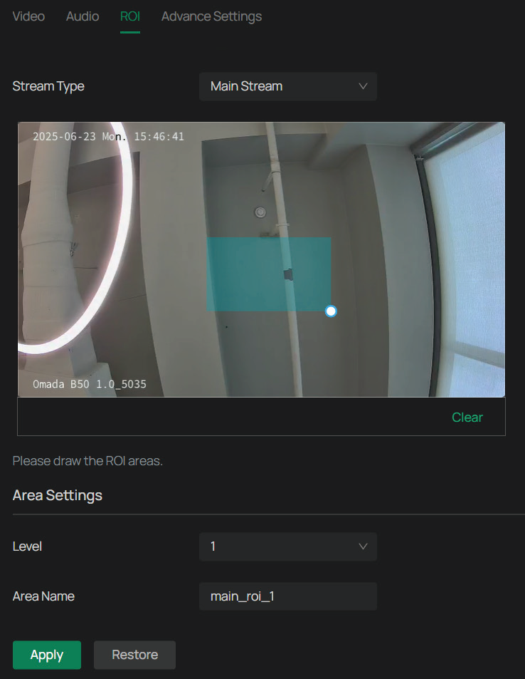
ROI
ROI (region of interest) concentrates on delivering high quality video from interested region. In ROI, you can configure the interest level of a specified area in each channel. The level 1–6 is ranked from low to high. The higher the ROI level, the better image quality.
1. Go to Settings > Camera > Stream > ROI.
2. Select the stream type and enable ROI. Draw an area on the preview screen (the blue square in the picture below). Drag to adjust its size and location. Specify the ROI level and name, and click Apply.
Advanced Settings
In Advanced Settings, you can set QoS and SRTP.
QoS (Quality of Service) can help improve the network delay and network congestion by setting the priority of data sending.
SRTP (Secure Real-time Transport Protocol) is a Real-time Transport Protocol (RTP) internet protocol, intended to provide encryption, message authentication and integrity, and replay attack protection to the RTP data in both unicast and multicast applications.
1. Go to Settings > Camera > Stream > Advanced Settings.
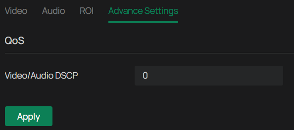
2. Set Video/Audio DSCP.
3. Network can identify the priority of data transmission. The bigger the DSCP value is, the higher the priority is.
4. Enable SRTP if needed. When enabled, RTSP video data will be encrypted and you may be unable to play the video using third-party clients or NVRs. It is recommended that you use the device together with an NVR.
5. Click Apply.
Events
This chapter guides you on how to configure the event settings and alarm actions when your cameras detect different types of events. The camera monitors your pre-defined areas and you’ll be automatically alerted to any suspicious activity in your home and office.
Arming Schedule and Processing Mode
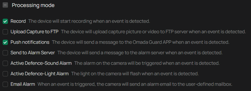
Arming schedule determines when a camera’s motion detection, recording, or other event-based features are active. It allows you to automate when the camera is actively monitoring and recording, based on a predefined schedule. Processing modes are the responses to the detected incidents or targets during the scheduled time. This configuration is optional.
1. Go to Settings > Event, and locate Arming Schedule and Processing Mode in the related event interface.
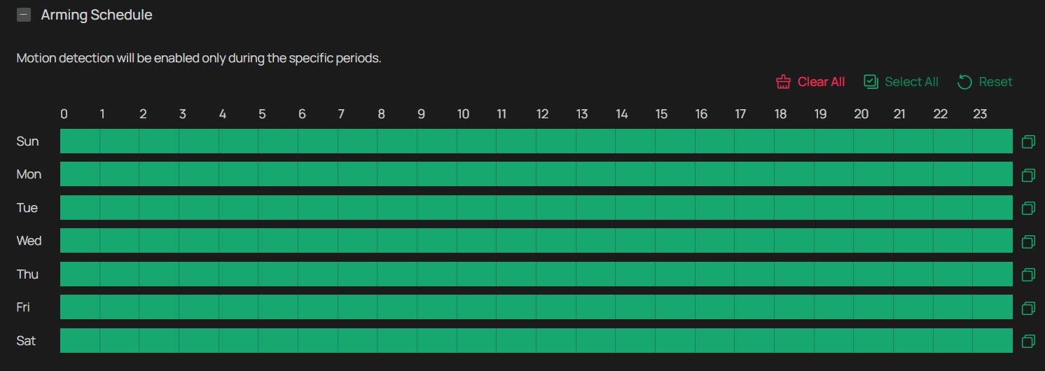
2. Drag the time bar to draw desired valid time.
Note:
1) Each cell represents one hour.
2) The default setting is 24/7.
3) Up to six time periods can be configured for a day.
3. Click a time block and an edit button will appear. Enter the pop-up window to finetune the Start Time and End Time (with an accuracy of a minute) and check Save.
4. Click ![]() to copy a schedule for a day to any other days. In the pop-up window, select the days of the week where you need to copy the time.
to copy a schedule for a day to any other days. In the pop-up window, select the days of the week where you need to copy the time.
5. Set processing modes as needed.
6. Click Apply.
Motion Detection
Motion detection allows cameras to detect the moving objects in the monitored area and triggers alarm actions. You can customize the motion detection settings, set the alarm schedule, and select the triggered actions. Follow the steps below to finish the configuration.
1. Go to Settings > Event > Basic Event > Motion Detection. Click the toggle to turn on Motion Detection.
2. Draw quadrilaterals for motion detection on the preview screen. The whole screen is selected by default. You may drag the corners to change the shape of the area and drag the whole area to move it. You may delete a selected area, clear all areas, expand the selected areas to the full screen, or add another area. Then configure the motion detection settings.
Note: You may customize up to four areas.
In Area Settings section, you may modify the following parameters:
| Parameter | Explanation |
|---|---|
| Sensitivity | Drag the slide bar to adjust the value. The higher the value is, the easier it is to trigger an alarm. |
| Object Filter | Click Set Max and Min Object to define the smallest and largest object sizes that will trigger events. |
3. Refer to Arming Schedule and Processing Mode for settings if needed.
4. Click Apply.
Camera Tampering
Camera tampering triggers alarm actions when an area of camera’s lens is purposely blocked, obstructed or vandalized. You can customize the video tampering settings, select the triggered actions and set the alarm schedule for cameras. Follow the steps below to finish the configuration.
1. Go to Settings > Event > Basic Event > Camera Tampering.
2. Enable Camera Tampering.
3. Set the sensitivity of video tampering. A higher value can trigger the alarm actions more easily.
4. Refer to Arming Schedule and Processing Mode for settings if needed.
5. Click Apply.
Human Detection
Human detection triggers alarm actions when cameras detect persons are moving in the specified areas. You can customize the area settings, select the triggered actions and set the alarm schedule.
Follow the steps below to finish the configuration.
1. Go to Settings > Event > Smart Event > Human Detection, and click the toggle to turn it on.
2. Adjust the value of sensitivity. A higher value can trigger alarm actions more easily.
3. Refer to Arming Schedule and Processing Mode for settings if needed.
4. Click Apply.
Vehicle Detection
Vehicle detection triggers alarm actions when cameras detect vehicles are moving in the specified areas. You can customize the area settings, select the triggered actions and set the alarm schedule.
Follow the steps below to finish the configuration.
1. Go to Settings > Event > Smart Event > Vehicle Detection, and click the toggle to turn it on.
2. Draw shapes for area exiting detection on the preview screen.
Note: You may draw up to four areas.
3. Adjust the value of sensitivity. A higher value can trigger alarm actions more easily.
4. Refer to Arming Schedule and Processing Mode for settings if needed.
5. Click Apply.
Pet Detection
Pet detection triggers alarm actions when cameras detect pets are moving in the specified areas. You can customize the area settings, select the triggered actions and set the alarm schedule. Follow the steps below to finish the configuration.
1. Go to Settings > Event > Smart Event > Pet Detection, and click the toggle to turn it on.
2. Adjust the value of sensitivity. A higher value can trigger alarm actions more easily.
3. Refer to Arming Schedule and Processing Mode for settings if needed.
4. Click Apply.
Line Crossing Detection
Line crossing detection triggers alarm actions when cameras detect that moving objects cross a customized virtual line. Follow the steps below to finish the configuration.
1. Go to Settings > Event > Smart Event > Line Crossing Detection, and click the toggle to turn it on.
2. Draw lines on the preview screen. Select the line and configure its settings.
Note: You can draw up to four lines and need to configure settings for each line.
| Parameter | Explanation |
|---|---|
| Sensitivity | The higher the value is, the easier it is to detect a target that crosses the line. |
| Direction | Choose the direction from which the target crosses the line. A->B: Only the target crossing the configured line from the A side to the B side can be detected. B->A: Only the target crossing the configured line from the B side to the A side can be detected. A<->B: The target going across the line from both sides can be detected and alarms are triggered. |
| Smart Detection | Choose whether you want to detect humans only, vehicles only, or both. The function is available only for cameras which support human detection and vehicle detection. |
| Smart Detection Confidence | Select the detection type from High, Medium, and Low. The function is available only for the cameras which support human detection and vehicle detection. |
| Object Filter | Click Set Max and Min Object to set the minimum and maximum object to filter the corresponding events. |
3. Refer to Arming Schedule and Processing Mode for settings if needed.
4. Click Apply.
Intrusion Detection
Intrusion detection is used to detect objects entering and loitering in a predefined virtual region. Once it happens, the camera will take linkage actions. Follow the steps below to finish the configuration.
1. Go to Settings > Event > Smart Event > Intrusion Detection, and enable it.
2. Draw intrusion areas on the preview screen. Select the area and configure the settings.
Note: You may draw up to four areas and need to configure settings for each area.
| Parameter | Explanation |
|---|---|
| Sensitivity | The higher the value is, the more easily an intrusion action can be detected. |
| Percentage | Set the percentage of intrusion detection. When an object takes up the specific percentage of the area, the alarm actions will be triggered. |
| Intrusion Time | Intrusion time stands for the threshold a target loiters in the area. Any stay longer than the intrusion time will trigger the linkage action. |
| Smart Detection | Choose whether you want to detect humans only, vehicles only, or both. The function is available only for cameras which support human detection and vehicle detection. |
| Smart Detection Confidence | Select the detection type from High, Medium, and Low. The function is available only for the cameras which support human detection and vehicle detection. |
| Object Filter | Click Set Max and Min Object to set the minimum and maximum object to filter the corresponding events. |
3. Refer to Arming Schedule and Processing Mode for settings if needed.
4. Click Apply.
Exception Event
Set the maximum login attempts to protect the security of your camera. The camera will be locked for 30 minutes if you enter the wrong password more than the specified attempts. Follow the steps below to finish the configuration.
1. Go to Settings > Event > Exception Event.
2. Enable Login Error Detection to limit the login attempts:
3. Set the maximum login attempts. The number should between 3 and 10
4. Click Apply.
Note: To unlock the camera and try to log in again, power the camera off and then power it on.
Smart Frame
Smart frame is an AI-powered function that can precisely mark and capture detected movement, people, or vehicle objects on the screen.
Click the toggles to specify the type of detection: motion, human, vehicle, or pet. You may enable more than one types. Click Apply.
Light Alarm (Only for some models)
With Light Alarm enabled, the light on the camera will flash when an event is detected. Follow the steps below to finish the configuration.
1. Go to Settings > Event > Active Defence > Light Alarm and toggle to enable it.
2. Configure the following paramters.
| Parameter | Explanation |
|---|---|
| Duration | The default duration is 5 seconds. Click Custom to set a duration between 5 and 35 seconds. |
| Flicker Frequency | From the drop-down menu, choose a flicker frequency: Low, Medium, or High. |
| Brightness | Drag the slider to adjust brightness between 0 and 100. Higher values increase the brightness of the light alarm. |
3. Refer to Arming Schedule and Processing Mode for settings if needed.
4. Click Apply.
Sound Alarm (Only for some models)
Enable Sound Alarm, then the alarm on the camera will be triggered when an event is detected.
1. Go to Settings > Event > Active Defence > Sound Alarm.
2. Enable Sound Alarm, select the Sound Type, and click Test.
3. Select the alarm times to set how many times the alarm sounds when triggered. The value is 5 by default. You may chooose Custom to set a value between 0 and 50.
4. Under Audio Output Settings, click the toggle to mute or drag the slide bar to set the system volume.
5. Refer to Arming Schedule and Processing Mode for settings if needed.
6. Click Apply.
Alarm Server
The device can send alarms to destination IP address or host name through HTTP, HTTPS, or ISUP protocol. The destination IP address or host name should support HTTP, HTTP, or ISUP data transmission.
1. Go to Settings > Event > Alarm Server.
2. Click Add.
3. Enter Host IP/Domain, URL, and Port, and select Protocol. Enable Attach Image if needed.
Note: HTTP and HTTPS are selectable. It is recommended to use HTTPS, as it encrypts the data transmission during communication.
4. Click Apply.
Smart Settings
This chapter guides you on how to configure settings about human or vehicle analysis on your camera. Some features require an NVR that has Smart Analysis compatibility.
Configuration
In the Configuration section, you may choose between the Smart Event Mode and Object Attribute Analysis Mode. The former enables the basic event and smart event features, while the latter can capture the human face or vehicle detected in the surveillance video and send it to the NVR for analysis and processing.
Please be advised that the Object Attribute Analysis Mode requires an NVR that supports the feature.
1. Go to Settings > Smart > Configuration.
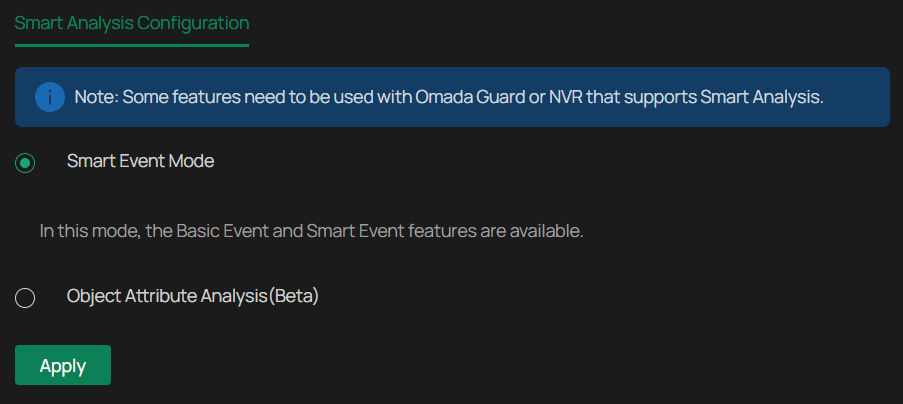
2. Select either Smart Event Mode or Object Attribute Analysis Mode. Note that only when Object Attribute Analysis Mode is enabled can you proceed with the Object Attribute Analysis feature.
3. Click Apply.
Object Attribute Analysis
In Object Attribute Analysis, you can choose whether to send human or vehicle images to the NVR for analysis.
1. Go to Settings > Smart > Object Attribute Analysis.
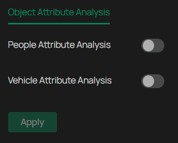
2. Enable People Attribute Analysis and/or Vehicle Attribute Analysis.
3. Click Apply.
Recording and Storage
This chapter guides you on how to view and configure recording and storage settings on your camera. You can set your own recording schedules and parameters.
Recording Schedule
Recording schedule section provides convenience and flexibility for the daily monitoring of your camera. You can customize the recording schedules. You can set different schedules for each day. In Advanced Settings page, you can set the pre-recording time and delay time for recording.
1. Go to Settings > Storage > Recording Schedule, and enable it.
2. Select Continuous, Event, or Motion.
| Parameter | Explanation |
|---|---|
| Continuous | The camera will record continuously. |
| Event | The camera will record when an event is detected. |
| Motion | The camera records when it detects human or vehicle motion. Click the vertical ellipsis next to Motion to select detection type: human motion, vehicle motion, or both. |
3. Drag the time bar to draw desired valid time.
Note:
Each cell represents one hour.
The default setting is 24/7.
Up to six time periods can be configured for a day.
4. Click a time block and an edit button will appear. Enter the pop-up window to finetune the Start Time and End Time (with an accuracy of a minute) and check Save.
5. To copy a schedule from one day to others, click ![]() . In the pop-up window, select the days you want to copy the schedule to.
. In the pop-up window, select the days you want to copy the schedule to.
6. Configure the following:
| Parameter | Explanation |
|---|---|
| Pre-recording Time | The time is set for cameras to record before the scheduled time or event. For example, the schedule for continuous recording starts at 10:00. If you set the pre-recording time as 5 seconds, the camera starts to record at 9:59:55. |
| Delay Time | The time is set for cameras to record after the scheduled time or event. For example, if you set the post-record time as 5 seconds, it records till 11:00:05 as motion detection ends at 11:00. |
5. Click Apply.
Storage Management
In Storage Management, you can view the parameters and configure the properties and disk group of SD card. You can also enable the camera to overwrite the earlier recording files when the SD card is full.
1. Go to Settings > Storage > Storage Management.
2. Click ![]() to initialize the memory card.
to initialize the memory card.
When the Status of memory card turns from Uninitialized to Normal, the memory card is ready for use.
3. Specify advanced settings.
| Parameter | Explanation |
|---|---|
| Record Streams | Select the stream type for recording. Main Stream stands for the best stream performance the device supports. It usually offers the best resolution and frame rate the device can do. But high resolution and frame rate usually means larger storage space and higher bandwidth requirements in transmission. Substream usually offers comparatively low resolution options, which consumes less bandwidth |
| Circular Write of Disk | Enable Circular Write of Disk to overwrite the video records when the storage space is full. Otherwise the camera cannot record new videos. |
| Record Audio | Enable to record audio and video simultaneously. |
| Recording Expiration | Enable Recording Expiration to delete recordings when they exceed the expired time. Note that once the recordings are deleted, they cannot be recovered. |
| Expired Time | Set the time when recordings will be automatically deleted. |
4. Click Apply.
Network Management
With proper network configurations, you can connect your camera to the internet, build up mapping between internal and external ports.
Internet Connection
In Internet Connection, you can view the connection status and configure the camera to obtain a dynamic or static IP address.
Follow the steps below to configure the network settings.
1. Go to Settings > Network Settings > Connect.
2. Configure the following:
| Parameter | Explanation |
|---|---|
| Status | Displays the current internet status. |
| IPv4 Mode | Configure the camera to obtain a dynamic or static IP address. |
| IPv4 Address | Specify an IP address for the camera. The IP address should be in the same segment as the gateway; otherwise, the camera cannot connect to the internet. |
| IPv4 Subnet Mask | Enter the subnet mask. |
| IPv4 Gateway | Enter the IP address of the gateway device to which the data packets will be sent. This IP address should be in the same segment as the camera’s IP address. |
| MAC Address | A unique identifier permanently assigned to the camera’s network interface card (NIC). It is used to identify the camera on a local network, enabling it to communicate with other devices on the same network segment. |
| DNS | Enter the IP address of the DNS server. |
| MTU | Specify MTU (Maximum Transmission Unit) to decide the largest size of data unit that can be transmitted in the network. A larger unit can improve the efficiency with more data in each packet, but it may increase the network delay because it needs more time to transmit. Therefore, if you have no special needs, it is recommended to keep the default value. |
| Adaptive IP | Enable this option if you want to set the camera’s IP to change according to the network topology. |
Note: The cameras should be in the same segment with the NVR, so that the NVR can discover and manage them.
3. Click Apply.
Network Service
In Network Service, you can configure the HTTPS port and service port of devices that can be used to access the camera through the network. When managing and monitoring the devices via the Omada Central or the Omada Guard app, the ports configured here are used for communications of corresponding protocols.
HTTPS Service
1. Go to Settings > Network Settings > Network Service > HTTP(S).
2. Specify HTTPS port and service ports.
| Parameter | Explanation |
|---|---|
| HTTPS Port | Specify a port for HTTPS protocol. |
| Web Stream Port | Specify a port for protocols of video services. |
| Video Service Port | Specify a port to access the camera’s live streaming web interface. |
| Digest Authentication Algorithm | Choose between MD5, SHA256, and MD5/SHA256. |
| RTSP | Specify a port for RTSP (Real Time Streaming Protocol) protocol. RTSP is an application layer protocol for connecting, transferring, and streaming media data in real time from IP cameras connected to the network. rtsp://username:password@ip:port/streamNo ip – IP of the Camera. port – Default port is 554. This can be skipped. streamNo – Stream number. Stream1 refers to the main stream; stream2 refers to the substream. Example URL: rtsp://admin:123456@192.168.1.60:554/stream1 This will display the main stream of the camera, where admin is the user name and 12345 is the password. |
3. Click Apply.
RTSP Service
1. Go to Settings > Network Settings > Network Service > RSTP.
2. Configure the following ports:
| Parameter | Explanation |
|---|---|
| RTSP | Specify a port for RTSP (Real Time Streaming Protocol) protocol. RTSP is an application layer protocol for connecting, transferring, and streaming media data in real time from IP cameras connected to the network. rtsp://username:password@ip:port/streamNo ip – IP of the Camera. port – Default port is 554. This can be skipped. streamNo – Stream number. Stream1 refers to the main stream; stream2 refers to the substream. Example URL: rtsp://admin:123456@192.168.1.60:554/stream1 This will display the main stream of the camera, where admin is the user name and 12345 is the password. |
| Digest Authentication Algorithm | Choose between MD5, SHA256, and MD5/SHA256. |
Platform Access
Omada Central is an application that streamlines batch device management via a single interface, integrating real-time video monitoring, an alarm center, and advanced features for effortless, robust security. You can access Omada Central with the Platform Access enabled.
1. Enable Access to Omada Central.
2. Scan the QR code with your Omada Guard app.
When the email is configured and enabled as a linkage method, the device sends an email notification to all designated recipients if an alarm event is detected.
1. Input the sender’s email information, including the Sender’s name, Sender Email, SMTP Server, and SMTP Port.
2. Enable SSL/TLS if needed and emails will be sent after encrypted.
3. Check Attached Image to receive notification with alarm pictures. The notification email has a certain number of attached alarm pictures about the event with configurable image capturing interval.
4. If your email server requires authentication, check Authentication and input your username and password to log in to the server.
5. Input the recipient’s information, including the recipient’s name and address.
6. Click Test to see if the function is well configured.
7. Click Apply.
Port Forwarding
Port Forwarding is used to establish the mapping between the internal port and external port. When Port Forwarding is enabled, you can access the device and watch the videos when accessing the external port remotely.
Note: The cameras should be connected to the internet, and Port Forwarding should be enabled on the gateway.
Follow the steps below to configure Port Forwarding.
1. Go to Settings > Network Settings > Port Forwarding.
2. Enable Port Forwarding and specify a mapping type. If you select Auto as the mapping type, the mappings are established automatically. If you select Manual as the mapping type, click to specify the external port.
| Parameter | Explanation |
|---|---|
| Port Type | Displays the protocol type. |
| Internal Port | Displays the port of the camera to be converted. |
| External Port | Displays the external port opened by the gateway. |
| Internal IP | Displays the IP address of the camera that needs to be converted. |
| Status | Displays the status of mapping. |
3. Click Apply.
With Port Forwarding enabled, you can remotely watch the videos with the URL rtsp://A.B.C.D:Port/streamN, for example, rtsp://10.0.1.47:28736/stream1. A.B.C.D is the WAN IP address of the gateway, and Port is the number of RTSP external port. N can be number 1 or 2 that indicates the stream, 1 for main stream and 2 for substream.
IP Restriction
When IP Restriction is enabled, you can add IP addresses to the deny list or allow list to restrict the access to the camera. The IP address in the deny list cannot access the camera, while only the IP addresses in the allow list can access the camera.
Follow the steps below to configure IP Restriction.
1. Go to Settings > Network Settings > IP Restriction.
2. Enable IP Restriction and specify the restriction rule. If you select Deny List, the devices with the IP addresses specified in the table will not be able to access the camera. If you select Allow List, only the devices with the IP addresses specified in the table can access the camera.
3. Click Add to add the desired IP address, give a description to identify this IP address, then click Save.
4. Click Apply.
Multicast
When Multicast is enabled, you can watch videos using the multicast address and port.
Follow the steps below to configure Multicast.
1. Go to Settings > Network Settings > Multicast.
2. Select the stream type, then enable Multicast.
3. Disable Random IP Port and specify a static address and port, or enable Random IP Port.
4. Click Apply.
After Multicast enabled, you can watch the video with the URL rtsp://A:B:C:D/multicastStreamN, for example, rtsp://192.168.0.3/multicastStream1. A.B.C.D is the IP address of the camera, and N can be number 1 or 2 that indicates the stream, 1 for main stream and 2 for substream.
Server
You can configure the FTP server to save images which are captured by events.
1. Go to Settings > Network Settings > FTP Settings > Server.
2. Check Enable Server. FTP and SFTP are selectable. The files uploading is encrypted by using SFTP protocol.
3. Enter Server Address and Port. They stand for the FTP server address and corresponding port.
4. Set Username and Password and confirm the password. The FTP user should have the permission to upload pictures.
5. If the FTP server supports picture uploading by anonymous users, you can check Anonymous to hide your device information during uploading.
Note: Anonymous login is not supported when SFTP protocol is selected.
6. Select the saving path of images uploaded in the dropdown box of Upload Path and Edit the Name.
7. Click Test to verify the FTP server.
8. Click Apply.
Upload
You can configure the parameters of videos and images to be uploaded to the FTP server.
1. Go to Settings > Network Settings > FTP Settings > Upload.
2. Enable Recording Schedule and follow the steps in Recording Schedule..
3. Enable Upload Video and Upload Capture as needed. Upload Video allows the system to automatically send recorded video clips to the configured FTP server. Upload Capture allows the system to upload snapshot images captured during events.
4. Configure the following parameters:
| Parameter | Explanation |
|---|---|
| Stream Type | Select the stream type for recording. Main Stream stands for the best stream performance the device supports. It usually offers the best resolution and frame rate the device can do. But high resolution and frame rate usually means larger storage space and higher bandwidth requirements in transmission. Substream usually offers comparatively low resolution options, which consumes less bandwidth |
| Record Audio | Enable to record audio and video simultaneously. |
| Pre-recording Time | The time period you set to record before the scheduled time. For example, the schedule for continuous recording starts at 10:00. If you set the pre-recording time as 5 seconds, the camera starts to record at 9:59:55. |
| Delay Time | The time is set for cameras to record after the scheduled time or event. For example, if you set the post-record time as 5 seconds, it records till 11:00:05 as motion detection ends at 11:00. |
| Max Size of a Single File | Set the size limit of a single file. |
| Capture Interval | The camera takes the capture when it reaches the capture interval. |
| Capture Number | The number of captures taken during one interval. |
5. Click Apply.
ONVIF
ONVIF (Open Network Video Interface Forum) is an open industry standard that enables IP cameras to work seamlessly with third-party video management systems, recorders, and software platforms. By enabling ONVIF, the camera can be discovered, configured, and controlled by other ONVIF-compliant devices—regardless of brand.
Enable ONVIF if you need to use third-party management devices.
1. Go to Settings > Network Settings > Advanced > ONVIF.
2. Configure the following:
| Parameter | Explanation |
|---|---|
| Open Network Video Interface | Enables ONVIF support, allowing the camera to connect with third-party video management systems that support the ONVIF protocol. |
| Automatically switch to static IP | When enabled, the device will automatically switch to a static IP address during ONVIF communication to ensure stable connectivity. |
| Onvif Port | For firmware version 1.6 and onwards, ONVIF uses port 80 and 2020 by default for communication; for earlier versions, the default port for ONVIF is 2020. |
| Time Verification | Ensures secure ONVIF access by verifying time consistency between the device and the client. Note: Before enabling Time Verification, make sure the device time is synchronized with the client to avoid authentication issues. |
3. Click Apply.
RTMP
RTMP (Real-Time Messaging Protocol) is a widely used streaming protocol that allows your IP camera to broadcast live video to platforms such as YouTube, Facebook Live, or custom media servers. This enables real-time video sharing over the internet with low latency and broad compatibility.
1. Go to Settings > Network Settings > Advanced > RTMP, and enable it.
2. Configure the following parameters.
Note: Ensure the main stream is encoded using H.264, as this is the only supported video codec for RTMP streaming.
Additionally, the G711 audio codec is used; some platforms may experience audio playback issues due to limited support for this format.
| Parameter | Explanation |
|---|---|
| Server Address | Enter the RTMP server URL provided by your streaming platform. This defines the destination where your camera’s video stream will be sent. |
| Stream Key | Enter the unique stream key assigned by your platform. This authenticates and links your camera’s feed to your specific live stream. |
3. Click Apply.
DDNS
You can use the Dynamic DNS (DDNS) for network access. The dynamic IP address of the device can be mapped to a domain name resolution server to realize the network access via domain name. Registration on the DDNS server is required before configuring the DDNS settings of the device.
1. Go to Settings > Network Settings > Advanced > DDNS.
2. Select the type of Service Provider for domain name resolution.
3. Enter the domain name information, and click Apply.
802.1x
802.1x is a network access control protocol that enhances security by requiring authentication before a device (like your IP camera) can connect to the network. When enabled, the camera must verify its identity through a configured authentication method before accessing the network, helping prevent unauthorized devices from joining.
1. Go to Settings > Network Settings > Advanced > 802.1x.
2. Configure the following:
| Parameter | Explanation |
|---|---|
| Protocol Type | Select the authentication method used by your network: EAP-MD5: Basic authentication using a username and password. EAP-LEAP: Cisco proprietary protocol that supports mutual authentication. EAP-PEAP: Encapsulates authentication within a secure TLS tunnel for improved security. Choose the protocol type that matches your network’s configuration. |
| EAPOL Version | Choose the version of EAP over LAN (EAPOL) protocol used for communication: 1: Compatible with older network infrastructures. 2: Used in most modern networks for enhanced performance and compatibility. |
3. Specify username, password, and click Apply.
Log Server
The Log Server feature allows your IP camera to automatically send system logs to a designated remote server for centralized monitoring, auditing, or troubleshooting. This is especially useful in multi-device environments where you want to track performance, errors, or security events from a central location.
1. Go to Settings > Network Settings > Log Server and enable it.
2. Configure the following:
| Parameter | Explanation |
|---|---|
| https | Enable it for encrypted transmission for added security. Tip: Use HTTPS when uploading logs over public or unsecured networks. |
| Upload Time Interval(h) | Defines how often the camera sends log data to the server. Enter a value between 1 and 24 hours. For example, entering 6 means the camera will upload logs every 6 hours. |
| Server IP Address | Enter the IP address or hostname of the log server where the logs will be sent. |
| Port | Specify the port number used by the server to receive log data. Common default ports: 80 for HTTP, and 443 for HTTPS. Always verify with your server administrator. |
3. Click Test and Apply.
System Settings
This chapter guides you to configure the basic and advanced settings of your camera, export and import settings. You can create and modify administrator accounts based on your needs.
Configure Basic Settings
1. Go to Settings > System Settings > Basic Settings.
2. View and change the name of your camera.
3. Specify the Web Session Timeout. You will be logged out when you make no operation (not including viewing live image) to the device via web browser within the set timeout period.
Modify System Time
You can select the time zone and set the time synchronization mode to Manual or NTP mode for the camera.
1. Go to Settings > System Settings > Basic Settings > Date.
2. Select your time zone.
3. Configure your time settings.
Network Time Protocol (NTP) is a protocol designed to time-synchronize a network of machines. NTP runs on User Datagram Protocol (UDP), which in turn runs on IP, or you can manually set the system time. If you do not want to expose your camera to the network, you can choose Manual. You may also click Synchronize with computer to synchronize the time settings of your camera with that of your PC.
| Parameter | Explanaruib |
|---|---|
| Server address | Enter the IP address of the NTP server. |
| Interval | Time interval between the two synchronizing actions with NTP server. Note: The interval can be set from1 to 10080 minutes, and the default value is 60 minutes. |
4. (Optional) Set DST (daylight saving time) parameters.
DST is the practice of setting the clocks forward one hour from standard time during the summer months, and back again in the fall. DST Bias is the difference in minutes between standard time and daylight-saving time for a specific time zone.
You can select Auto at the dropdown list. Note that to update the time automatically with the DST, internet connection is required.
Or you can select Manual and specify the date/time of the DST period.
Note:
1. In some time zones, DST is not observed.
2. If the camera is connected to an NVR, you only need to configure NTP and DST settings on the NVR, which will be synchronized with the camera.
5. Click Apply.
Manage User Accounts
You can modify the default user account (admin) based on your needs. The Administrator user name is admin and the password is set when you set up your camera for the first time.
1. Go to Settings > System Settings > User Management.
2. Click Add. Enter Username, select User Group, and enter Password. Assign remote permission to users based on needs.
Note: The system pre-defines a default user group: administrator, which has all the permission of the system. You can click Edit to view the details and operations. The permission list of the administrator cannot be edited.
| Parameter | Explanation |
|---|---|
| Administrator | The administrator has the authority to all operations and can add users and operators and assign permission. |
| Operator | Operators can be assigned all permission except for operations on the administrator and creating accounts. |
| User | Users can be assigned permission of viewing live video, setting PTZ and event parameters, and changing their own passwords, but no permission for other operations. |
3. (Optional) After adding the role, you can do one or more of the following:
Set the permission for the user. Under the Permission List, check the accesses you grant to the user.
Add a remark for the user. Enter your personalized notes in the Remark field.
4. Click Password Protection for account security settings. You can reset the password by setting the security question or email. You can click Forget Password and answer the security question to reset the admin password when access the device via browser. After setting the email, you can receive the verification code during the recovering operation process.
System Management
You can reset the camera to factory default settings, import and export the configuration file of your camera. To configure these settings, go to Settings > System Settings > System Management.
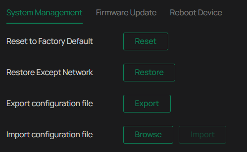
To reset all the parameters to the factory default, click Reset.
To reset device parameters, excluding network settings, to the factory default, click Restore.
Note: After you click Restore, the port number you set in Network Settings will change.
To export the configuration file, click Export.
To import the configuration file, click Browse to select your file, then click Import.
Upgrade Firmware
TP-Link aims at providing better network experience for users. We will inform you through the web management page if there’s any update firmware available for your camera. Also, the latest firmware will be released at the TP-Link official website www.tp-link.com, and you can download it for free.
Note:
Backup your camera configuration before firmware upgrade.
Do NOT power off the camera during the firmware upgrade.
Online Upgrade
1. Go to Settings > System Settings > System Management > Upgrade Firmware.
2. Click Check for Update to see whether the latest firmware is released.
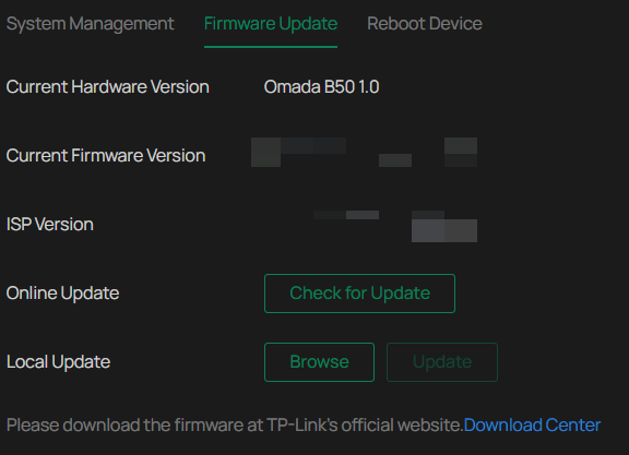
3. Navigate to the Online Upgrade section, and click Upgrade if there is new firmware.
Wait a few minutes for the upgrade and reboot to complete.
Local Upgrade
1. Download the latest firmware file for the camera from www.tp-link.com.
2. Go to Settings > System Settings >System Management > Upgrade Firmware.
3. Click Browse to locate the downloaded new firmware file, and click Update.
4. Wait a few minutes for the upgrade and reboot to complete.
Reboot Device Regularly
The Scheduled Reboot feature cleans the cache to enhance the running performance of the camera.
1. Go to Settings > System Settings > System Management > Reboot Device.
2. Enable Scheduled Reboot.
3. Select the day and time and specify the Float Range. When Fixed Time is selected, the camera will reboot at exactly the time you set in the Reboot Schedule. You may select 1 to 60 minutes. Then your camera will reboot some time before or after the time you set in the Reboot Schedule.
4. Click Save.
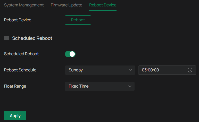
Note: You can click Reboot Now to reboot the camera immediately.
