


About This Guide
This Configuration Guide provides information for configuring the Easy Managed Switch via the web interface. Read this guide carefully before operation.
You can also configure and manage the switch using the Omada Controller. For more information, refer to the Omada SDN Controller User Guide. Go to the website https://support.omadanetworks.com/, search Omada SDN Controller, and you can find the guide on the product Support web page.
Intended Readers
This Guide is intended for network managers familiar with IT concepts and network terminologies.
Conventions
When using this guide, notice that features available in Easy Managed Switch may vary by model and software version. The availability of Easy Managed Switch may also vary by region or ISP. All images, steps, and descriptions in this guide are only examples and may not reflect your actual experience.
Throughout the guide, we will take a specific model as the switch to be configured for example.
Some models featured in this guide may be unavailable in your country or region. For local sales information, visit https://www.omadanetworks.com/.
The information in this document is subject to change without notice. Every effort has been made in the preparation of this document to ensure accuracy of the contents, but all statements, information and recommendations in this document do not constitute the warranty of any kind, express or implied. Users must take full responsibility for their application of any products.
In this Guide, the following conventions are used:
Menu Name > Submenu Name > Tab page indicates the menu structure. SYSTEM > System Info > System Summary means the System Summary page under the System Info menu option that is located under the SYSTEM menu.
Bold font indicates a button, toolbar icon, menu or menu item.
| Note: Notes contain suggestions or references that help you make better use of your device. |
|---|
More Resources
| Main Site | https://www.omadanetworks.com/ |
|---|---|
| Video Center | https://support.omadanetworks.com/video/ |
| Documents | https://support.omadanetworks.com/document/ |
| Product Support | https://support.omadanetworks.com/product/ |
| Technical Support | https://support.omadanetworks.com/contact-support/ |
For technical support, the latest software, and management app, visit https://support.omadanetworks.com/.
Introduction
Product Overview
Easy Managed Switch is an ideal upgrade from Unmanaged Switch, designed for Small Office and Home Office networks. The switch supports the following features:
· Traffic monitoring: Traffic summary, port mirroring, loop prevention and cable test enable the administrator to monitor traffic of the network effectively.
· VLAN: MTU VLAN, Port-based VLAN and 802.1Q VLAN can restrict broadcast domain, enhance network security and help manage devices easily.
· QoS: Port-based QoS, 802.1P-based QoS and DSCP/802.1P based QoS optimize traffic on your business network, and keep latency-sensitive traffic moving smoothly. Rate limit helps distribute and utilize network bandwidth reasonably. Storm control helps avoid network broadcast storm.
· PoE: PoE (Power over Ethernet) is a remote power supply function. With this function, the switch can supply power to the connected devices over twisted-pair cables.
| Note: The PoE Config is only available on Easy Managed Switches with PoE ports. For other non-PoE Easy Managed Switches, this feature is not supported. |
|---|
Logging Into the Switch
To configure your switch through a web browser on your PC, follow these steps:
1) Connect your switch to the network and connect your PC to the switch.
2) Find out the IP address of the switch.
· By default, the switch receives an IP address from a DHCP server (or a router that functions as a DHCP server) in your network. You can find out this IP address on the DHCP server.
· If the switch cannot receive an IP address from a DHCP server, it uses the static IP address of 192.168.0.1, with a subnet mask of 255.255.255.0.
3) Configure IP address on your PC to make sure the switch and PC are in the same subnet.
· If the switch uses an IP address assigned by a DHCP server, set your PC to obtain an IP address automatically from the DHCP server.
· If the switch uses the static IP address of 192.168.0.1, configure your PC’s IP address as 192.168.0.x (”x” ranges from 2 to 254), and subnet mask as 255.255.255.0.
4) Launch a web browser on your PC. The supported web browsers include, but are not limited to, the following types:
· Edge 134.0.3124.51
· Chrome 135.0.7039.0
· Firefox 136.0
· Safari 15.6.1
5) In the address bar of the web browser, enter the IP address of the switch. Here we suppose the switch uses the static IP address 192.168.0.1.

6) Enter the username and password in the pop-up login window to log into the switch.
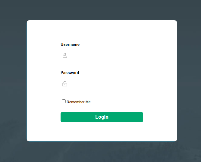
| Note: The first time you log in, you will have to set your username and password first. |
|---|
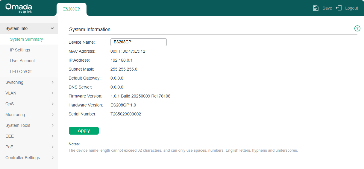
7) The typical web interface displays below. You can view the running status of the switch and configure the switch on this interface.
| Note: After applying the settings, you need to click the Save button on the upper right of the page to put the configuration into effect. |
|---|
Managing System
System
Overview
In the System Info module, you can view the system information and configure the system parameters and features of the switch.
Supported Features
System Summary
System Summary is mainly used to view the system information and configure the device name.
IP Settings
Each device in the network possesses a unique IP address. You can access the switch using IP address of the switch. You can set IP address of the switch manually or using DHCP.
User Account
User Account is mainly used to modify the administrator’s username and password in order to refuse illegal users.
LED On/Off
LED On/Off config is used to turn on or off the LED on the switch.
System Summary
With System Summary, you can:
· View the system information
· Specify the device name
Viewing the System Information
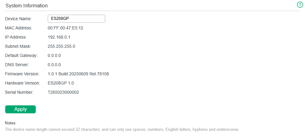
Choose the menu System Info > System Summary to load the following page. You can view the basic system information of the switch.
| Note: The Serial Number of the switch can be used to add the device to the Omada Cloud-Based Controller. |
|---|
Specifying the Device Name
Choose the menu System Info > System Summary to load the following page. Specify a new device name for the switch, and click Apply.
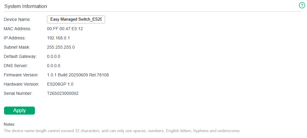
| Note: The device name length cannot exceed 32 characters, and can only use spaces, numbers, English letters, hyphens and underscores. |
|---|
Configuring IP
You can configure the system IP address in the following two ways:
· Configure the System IP Address Using DHCP
· Configure the System IP Address Manually
Configuring the System IP Address Using DHCP
Choose the menu System Info > IP Settings to load the following page.
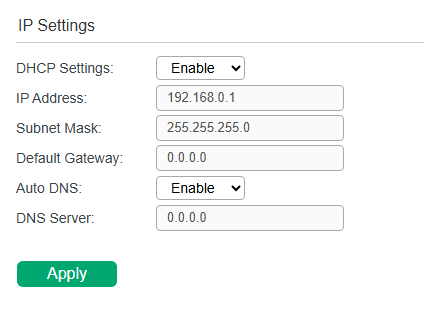
Follow these steps to configure the system IP address using DHCP:
1) Select DHCP Settings as Enable from the drop-down list.
2) Configure Auto DNS.
a) Select Auto DNS as Enable from the drop-down list. The switch will obtain the DNS server’s IP address from the DHCP Server.
b) Select Auto DNS as Disable from the drop-down list. You can specify the DNS server’s IP address of the switch.
3) Click Apply. The switch will obtain IP settings from the DHCP server.
Configuring the System IP Address Manually
Choose the menu System Info > IP Settings to load the following page.
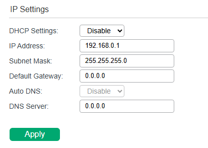
Follow these steps to configure the system IP address manually:
1) Select DHCP Settings as Disable from the drop-down list.
2) Specify the IP address, subnet mask, default gateway and DNS server.
| IP Address | Specify the system IP of the switch. You can use this IP address to access the switch. |
|---|---|
| Subnet Mask | Specify the subnet mask of the switch. |
| Default Gateway | Specify the default gateway of the switch. |
| DNS Server | Specify the DNS server’s IP address of the switch. |
3) Click Apply.
Configuring User Account
With User Account, you can modify the administrator’s username and password in order to refuse illegal users.
Choose the menu System Info > User Account to load the following page.
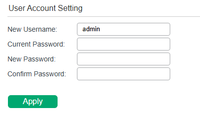
Follow these steps to configure the user account:
1) Specify the new username, enter the current password, specify a new password and confirm the new password.
| New Username | Create a user name for login. Requirement for the user name varies among different devices. If your user name fails to meet the requirement, check the prompt information. |
|---|---|
| Current Password | Enter the current password of the switch. |
| New Password | Specify a new password for login. Requirement for the password varies among different devices. If your password fails to meet the requirement, check the prompt information. |
| Confirm Password | Retype the new password. |
2) Click Apply.
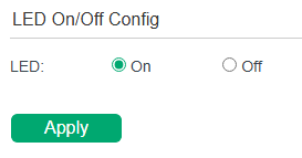
Configuring LED
With this function, you can turn on or turn off the LED with one click.
Choose the menu System Info > LED On/Off to load the following page. Choose the LED status and click Apply.
Appendix: Default Parameters
Default setting of System Summary is listed in the following table.
| Parameter | Default Setting |
|---|---|
| Device Name | The model name of the switch. |
Default settings of IP Settings are listed in the following table.
| Parameter | Default Setting |
|---|---|
| DHCP Setting |
Enable |
| IP Address | 192.168.0.1 |
| Subnet Mask | 255.255.255.0 |
| Default Gateway | 0.0.0.0 |
| Auto DNS | Enable |
| DNS Server |
0.0.0.0 |
Default setting of User Account is listed in the following table.
| Parameter | Default Setting |
|---|---|
| New Username | admin |
Switching
Switching
Overview
With the Switching feature, you can configure Port Settings, Digital Diagnostics Monitoring (DDM), IGMP Snooping and Link Aggregation Group (LAG).
Supported Features
The switch supports the following features about switching:
Port Settings
You can configure port state, speed, duplex mode and flow control for ports.
Digital Diagnostics Monitoring (DDM)
With the Digital Diagnostics Monitoring (DDM) function, you can monitor and manage the SFP modules inserted into the SFP ports. You can configure multiple thresholds for the SFP module. The SFP port can be automatically shut down when the switch detects the operating parameter of the module exceeds the threshold.
IGMP Snooping
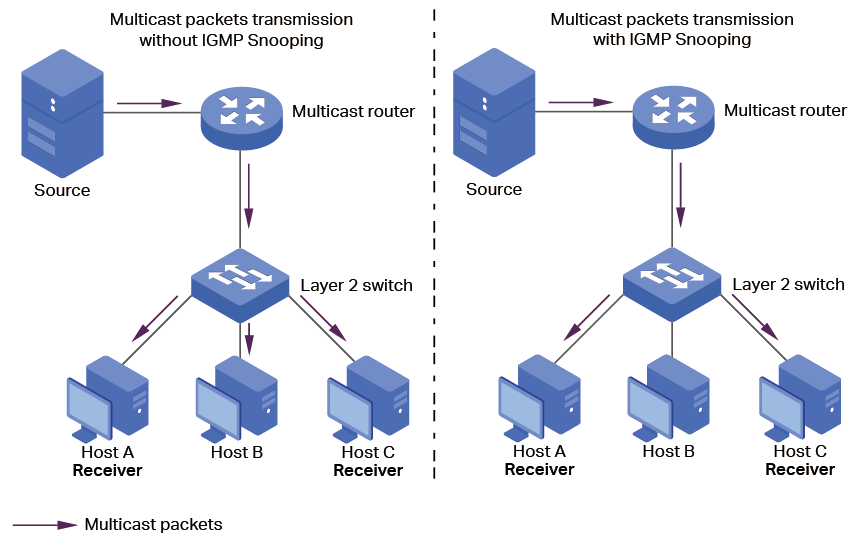
In a point-to-multipoint network, packets can be sent in three ways: unicast, broadcast and multicast. With unicast, many copies of the same information will be sent to all the receivers, occupying a large bandwidth.
With broadcast, information will be sent to all users in the network no matter they need it or not, wasting network resources and impacting information security.
Multicast, however, solves all the problems caused by unicast and broadcast. With multicast, the source only needs to send one piece of information, and all and only the users who need the information will receive copies of the information. In a point‑to‑multipoint network, multicast technology not only transmits data with high efficiency, but also saves a large bandwidth and reduces network load.
When IGMP Snooping is disabled on the switch, multicast packets will be broadcast in the Layer 2 network; when IGMP Snooping is enabled on the switch, multicast data from a known multicast group will be transmitted to the designated receivers instead of being broadcast in the Layer2 network. The following figure shows how IGMP snooping works.
Link Aggregation Group (LAG)
With the Link Aggregation Group (LAG) function, you can aggregate multiple physical ports into a logical interface to increase link bandwidth and enhance the connection reliability.
Configuring Ports
Choose the menu Switching > Port Settings to load the following page.
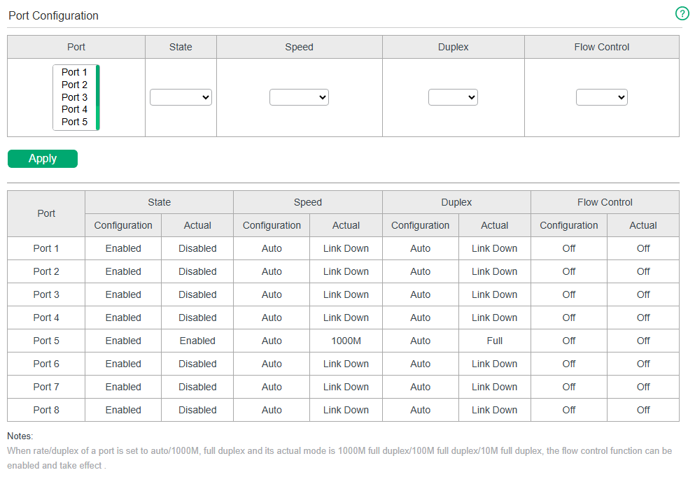
Follow these steps to configure the port parameters.
1) Select the desired ports and set basic parameters for the ports.
| State | Enable or disable the port. When Enable is selected, the port can forward the packets normally. |
|---|---|
| Speed | Select the speed mode for the port. You can select Auto or manually specify the speed mode. When Auto is selected, the speed mode will be automatically determined by auto-negotiation. The device connected to the port should be in the same speed mode as the port. |
| Duplex | Select the duplex mode for the port. You can select Auto or manually specify the duplex mode. When Auto is selected, the duplex mode will be automatically determined by auto-negotiation. The device connected to the port should be in the same duplex mode as the port. |
| Flow Control | Select On or Off to enable or disable the Flow Control feature. When On is selected, the switch can synchronize the speed with its peer to avoid the packet loss caused by congestion. |
2) Click Apply.
|
Note: · It is recommended to set the ports on both ends of a link with the same speed and duplex mode. · Keep the port that is connected to the management device enabled, or you cannot access the switch. · The parameters of the port members in a LAG should be set as the same. |
|---|
Configuring DDM (Only for Certain Models)
To configure DDM, follow these steps:
1) Enable DDM and set the shutdown condition.
2) Configure the DDM thresholds.
3) View the DDM status.
|
Note: |
|---|
Enabling DDM and Setting Shutdown Condition
Choose the menu Switching > DDM > DDM Config to load the following page.
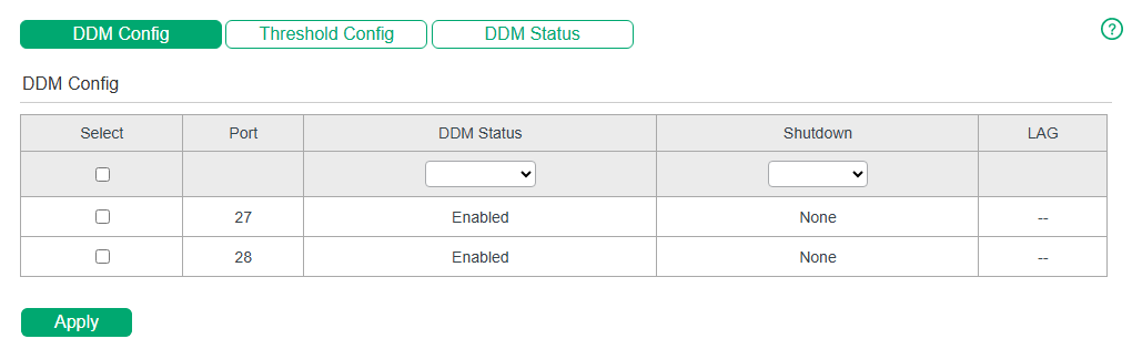
Follow these steps to configure DDM.
1) Select one or more SFP ports and enable DDM in the DDM Status drop-down list.
2) Set the shutdown condition for each SFP port. Click Apply.
| DDM Status | Displays the DDM status of each SFP port. |
|---|---|
| Shutdown |
Displays the shutdown condition of each SFP port. None: The port will never be shut down regardless of whether the threshold ranges are exceeded or not. This is the default setting. Alarm: The port will be shut down when the configured alarm threshold range is exceeded. Warning: The port will be shut down when the configured warning threshold range is exceeded. |
| LAG | Displays the LAG that the port belongs to. |
Configuring DDM Thresholds
Choose the menu Switching > DDM > Threshold Config to load the following page.
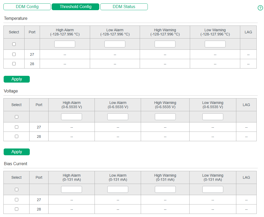
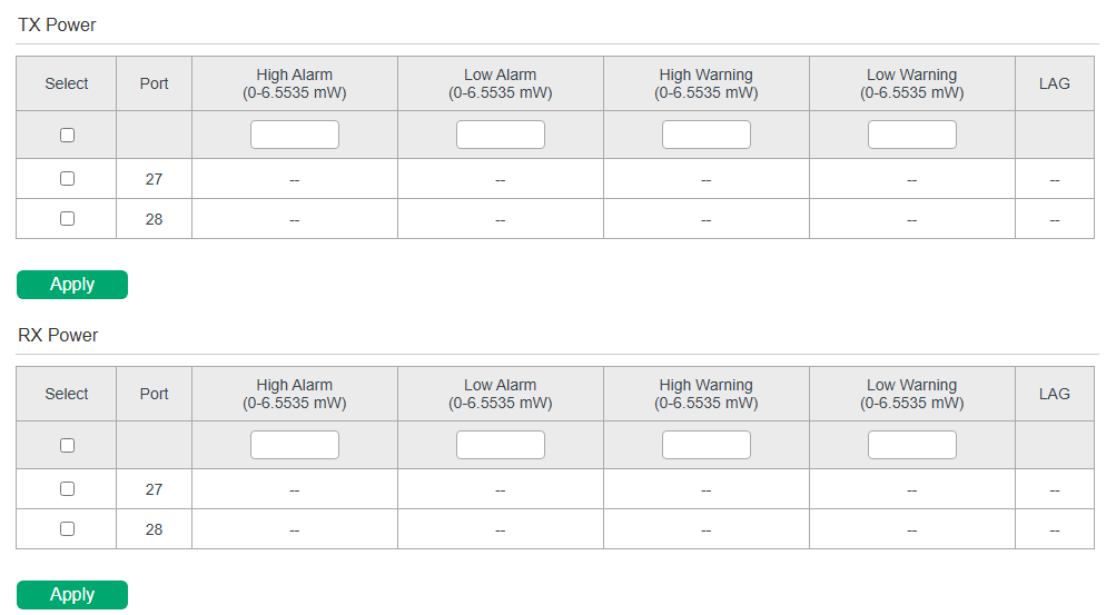
Follow these steps to configure the DDM temperature / voltage / bias current / TX power / RX power thresholds for the SFP ports.
1) Select one or more SFP ports and specify the DDM threshold in the corresponding section.
2) Click Apply.
| High Alarm | Specify the highest threshold for the alarm. When the operating parameter rises above this value, action associated with the alarm will be taken. |
|---|---|
| Low Alarm | Specify the lowest threshold for the alarm. When the operating parameter falls below this value, action associated with the alarm will be taken. |
| High Warning | Specify the highest threshold for the warning. When the operating parameter rises above this value, action associated with the warning will be taken. |
| Low Warning | Specify the lowest threshold for the warning. When the operating parameter falls below this value, action associated with the warning will be taken. |
| LAG | Displays the LAG that the port belongs to. |
|
Note: |
|---|
Viewing DDM Status
Choose the menu Switching > DDM > DDM Status to load the following page. You can view the current working parameters of the SFP modules inserted into a SFP port.
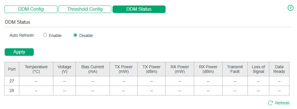
| Auto Refresh | With this option enabled, the switch will automatically refresh the DDM status every 5 seconds. |
|---|---|
| Refresh | Click to manually refresh the DDM status. |
| Temperature | Displays the current temperature of the SFP module inserted into a specific port. |
| Voltage | Displays the current voltage of the SFP module inserted into a specific port. |
| Bias Current | Displays the current bias current of the SFP module inserted into a specific port. |
| Tx Power | Displays the current Tx power of the SFP module inserted into a specific port in mW and in dBm. |
| Rx Power | Displays the current Rx power of the SFP module inserted into a specific port in mW and in dBm. |
| Transmit Fault | Reports remote SFP module signal loss. The values are True, False and No Signal. |
| Loss of Signal | Reports local SFP module signal loss. The values are True and False. |
| Data Ready | Indicates whether the SFP module is operational. The values are True and False. |
Configuring IGMP Snooping
Choose the menu Switching > IGMP Snooping to load the following page.
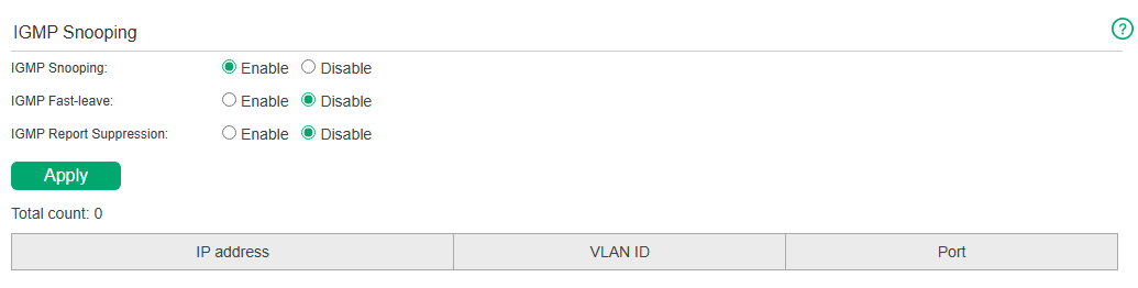
Follow these steps to configure IGMP Snooping.
1) Enable IGMP Snooping. Enable or disable IGMP Fast-leave and report message suppression according to your needs. Click Apply.
| IGMP Snooping | Enable or disable IGMP Snooping globally. |
|---|---|
| IGMP Fast-leave | Enable or disable Fast Leave globally. |
| IGMP Report Suppression | Enable or disable Report Message Suppression function globally. If this function is enabled, the first Report Message from the listener will forward to the router ports while the subsequent Report Message will be suppressed to reduce the IGMP packets. |
2) In the table below, you can view the current IGMP group information.
| IP Address | Displays the IP address of the multicast group. |
|---|---|
| VLAN ID | Displays the VLAN ID of the multicast group. All port members of a multicast group should be included in the same VLAN. |
| Port | Displays the forwarding port list of the multicast group. |
Configuring LAG
Choose the menu Switching > LAG to load the following page.
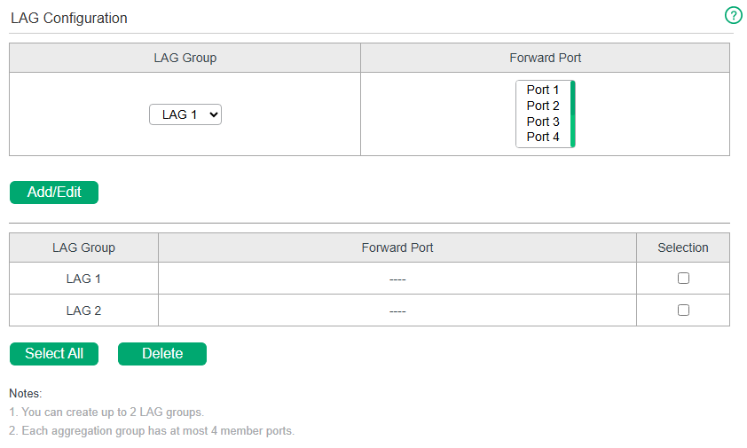
Follow these steps to configure LAG:
1) Select the desired LAG group from the drop-down list.
2) Click the ports to add to the LAG group. Click Apply.
3) In the table below, you can verify the LAG configuration result. You can select the LAG and click Delete to delete ports from the LAG group.
| LAG Group | Displays the group number of the LAG Group. |
|---|---|
| Forward Port | Displays the LAG Group member ports. |
| Selection | Select the LAG Group. |
|
Note: |
|---|
Configuration Examples
Example for Configuring IGMP Snooping
Network Requirements
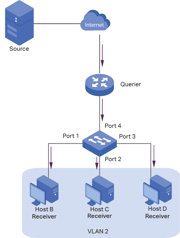
Host B, Host C and Host D are in the same VLAN of the switch. All of them want to receive multicast streams sent to the same multicast group.
As shown in the following topology, Host B, Host C and Host D are connected to port 1, port 2 and port 3 respectively. Port 4 is the router port connected to the multicast querier.
Configuration Scheme
· Configure 802.1Q VLAN. Add the three member ports and the router port to the same VLAN.
· Enable IGMP Snooping.
Demonstrated with a specific model, the following section provides configuration steps.
Configuration Steps
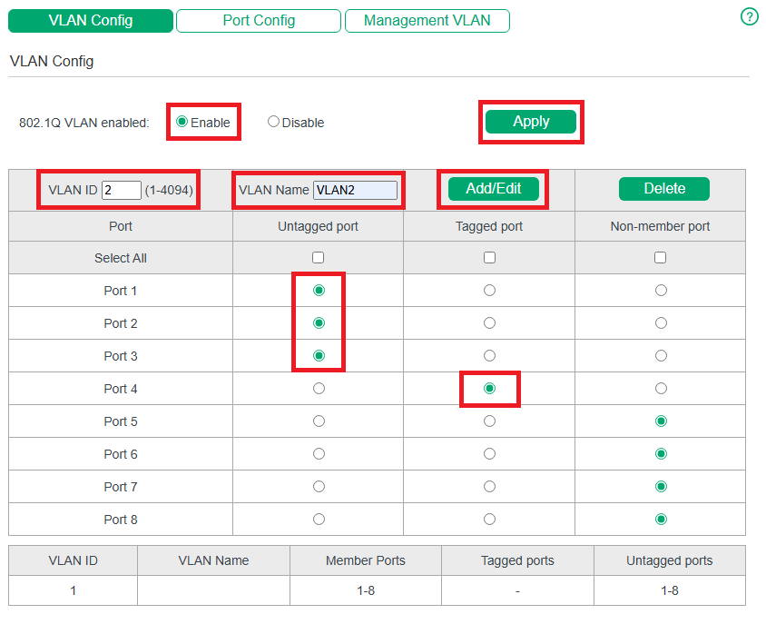
1) Choose the menu VLAN > 802.1Q VLAN > VLAN Config to load the following page. Select the 802.1Q VLAN Configuration as Enable. Click Apply. Specify the VLAN ID as 2. Specify the VLAN name as VLAN2. Select port 1, port 2, port 3 as untagged ports. Select port 4 as a tagged port. Click Add/Edit.
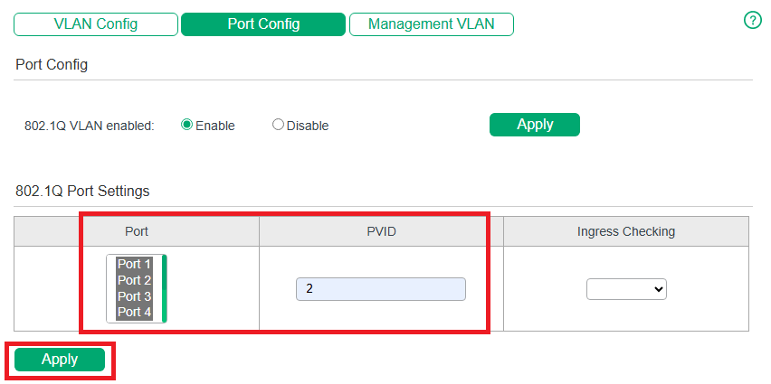
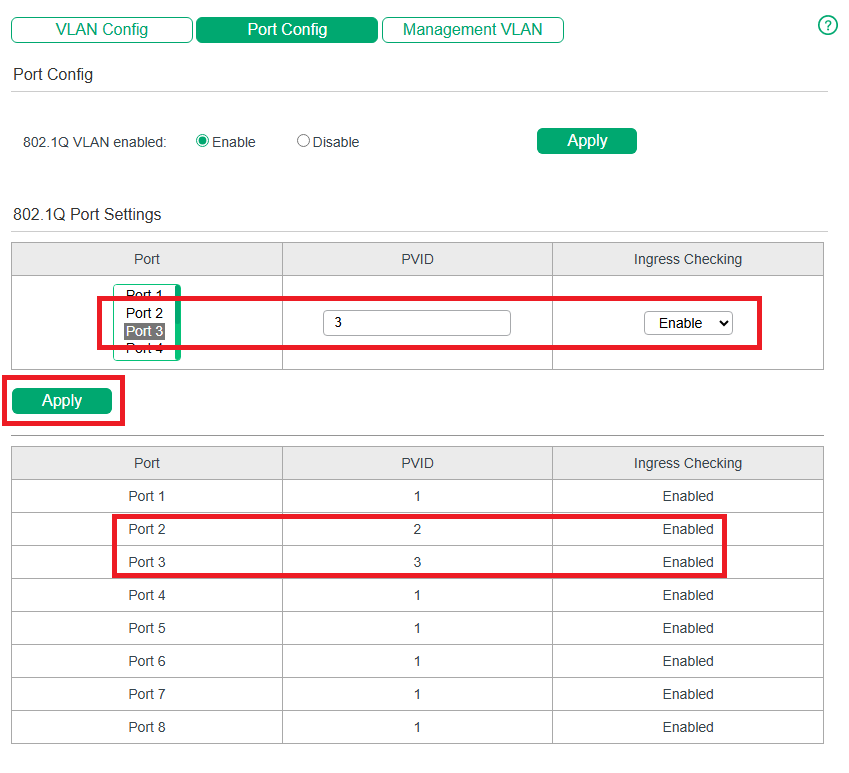
2) Choose the menu VLAN > 802.1Q VLAN > Port Config to load the following page. Select port 1, port 2, port 3 and port 4, and specify the PVID as 2 for the ports. Click Apply.
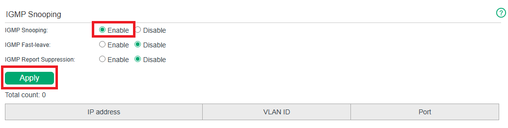
3) Choose the menu Switching > IGMP Snooping to load the following page. Enable IGMP snooping. Click Apply.
Example for Configuring LAG
Network Requirements
As shown below, hosts and servers are connected to Switch A and Switch B, and heavy traffic is transmitted between the two switches. To achieve high speed and reliability of data transmission, you can bundle multiple physical ports into one logical interface. In this case, we bundle port 1, port 2 and port 3 of both switches into one logical interface.
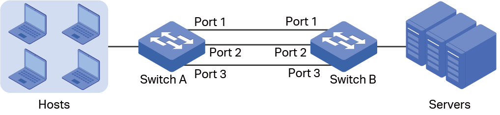
Demonstrated with a specific model, the following section provides configuration steps. The configuration steps are similar for both switches, here we take Switch A for example.
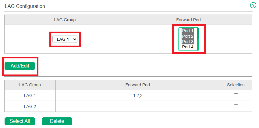
Configuration Steps
Choose the menu Switching > LAG to load the following page. Add Port 1, Port 2 and Port 3 to LAG 1. Click Add/Edit.
Appendix: Default Parameters
Default settings of Port are listed in the following table.
| Parameter | Default Setting |
|---|---|
| State | Enabled |
| Speed | Auto |
| Duplex | Auto |
| Flow Control | Off |
Default settings of IGMP Snooping are listed in the following table.
| Parameter | Default Setting |
|---|---|
| IGMP Snooping | Enable |
| IGMP Fast-leave | Disable |
| IGMP Report Suppression | Disable |
Default settings of LAG are listed in the following table.
| Parameter | Default Setting |
|---|---|
| LAG Group | LAG 1 (No port configured) |
Configuring VLAN
Overview
VLAN (Virtual Local Area Network) is a network technique that solves broadcasting issues in local area networks. It is usually applied in the following occasions:
· To restrict broadcast domain: VLAN technique divides a big local area network into several VLANs, and all VLAN traffic remains within its VLAN. It reduces the influence of broadcast traffic in Layer 2 network to the whole network.
· To enhance network security: Devices from different VLANs cannot achieve Layer 2 communication, and thus users can group and isolate devices to enhance network security.
· To facilitate management: VLANs group devices logically instead of physically, so devices in the same VLAN need not be located in the same place. It eases the management of devices in the same work group but located in different places.
There are 3 types of VLAN modes supported on the switch:
· MTU VLAN
MTU VLAN (Multi-Tenant Unit VLAN) defines an uplink port which will build up several VLANs with each of the other ports. Each VLAN contains two ports, the uplink port and one of the other ports in the switch, so the device connected to the uplink port can communicate with the device connected to any other port, but devices connected to other ports cannot communicate with each other.
· Port-Based VLAN
VLANs are divided based on ports. In port based VLAN mode, each port can only be added to one VLAN.
· 802.1Q VLAN
The IEEE 802.1Q protocol defines a new format of VLAN data frame (Tagged Frame). As the following figure shows, compared to the traditional Ethernet data frame (Untagged Frame), the VLAN data frame (Tagged Frame) adds a VLAN tag.
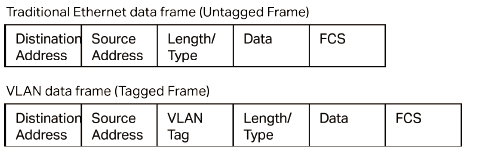
On receiving a tagged frame, the switch checks the VID (VLAN ID) contained in the VLAN tag to determine which VLAN the frame belongs to. On receiving an untagged frame, the switch will first insert a VLAN tag to the frame, using the PVID (Port VLAN ID) of the port as its VID, and then forward it as a tagged frame.
| Note: · The switch works in one and only one VLAN mode at any time. When a specific VLAN mode is enabled, the other two VLAN modes will be disabled automatically and the corresponding VLAN configuration will be lost. · The switch supports up to 32 VLANs simultaneously. |
|---|
Configuring MTU VLAN
Choose the menu VLAN > MTU VLAN to load the following page.
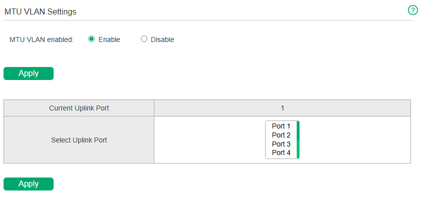
Follow these steps to configure MTU VLAN:
1) Select MTU VLAN configuration as Enable. Click Apply.
| MTU VLAN enabled | Check the box to enable/disable the MTU VLAN mode. |
|---|
2) In the table below, change the uplink port from the list according to your needs. Click Apply.
| Current Uplink Port | Displays the current uplink port of the MTU VLAN. |
|---|---|
| Select Uplink Port | Select the desired uplink port(s) from the list. The uplink port will build up several VLANs with each of the other ports. |
Configuring Port-Based VLAN
Choose the menu VLAN > Port-based VLAN to load the following page.
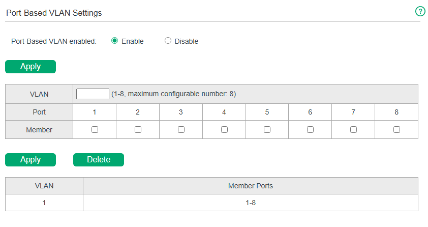
Follow these step to configure port-based VLAN:
1) Select the port-based VLAN configuration as Enable. Click Apply.
| Port-based VLAN enabled | Check the box to enable/disable the Port-based VLAN. |
|---|
2) Enter the VLAN ID and select ports to be added to the VLAN. Click Apply. To delete the VLAN created, enter the corresponding VLAN ID and click Delete.
| VLAN | Enter the ID number of VLAN. It ranges from 1 to 32. |
|---|---|
| Port | Displays the port number. |
| Member | Click the checkbox to choose one or multiple member ports of the current VLAN. If this field is checked, it indicates the port belongs to the current VLAN. |
3) In the table below, you can verify the configuration result of the port-based VLAN.
| VLAN | Displays the ID number of VLAN. |
|---|---|
| Member Ports | Displays the member ports in the VLAN. |
|
Note: |
|---|
Configuring 802.1Q VLAN
To complete the 802.1Q configuration, follow these steps:
1) Configure the VLAN, including creating a VLAN and adding the ports to the VLAN.
2) Configure the PVID.
3) Configure the management VLAN.
Configuring the VLAN
Choose the menu VLAN > 802.1Q VLAN > VLAN Config to load the following page.
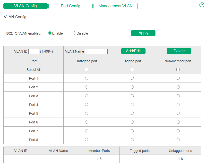
Follow these steps to configure the VLAN:
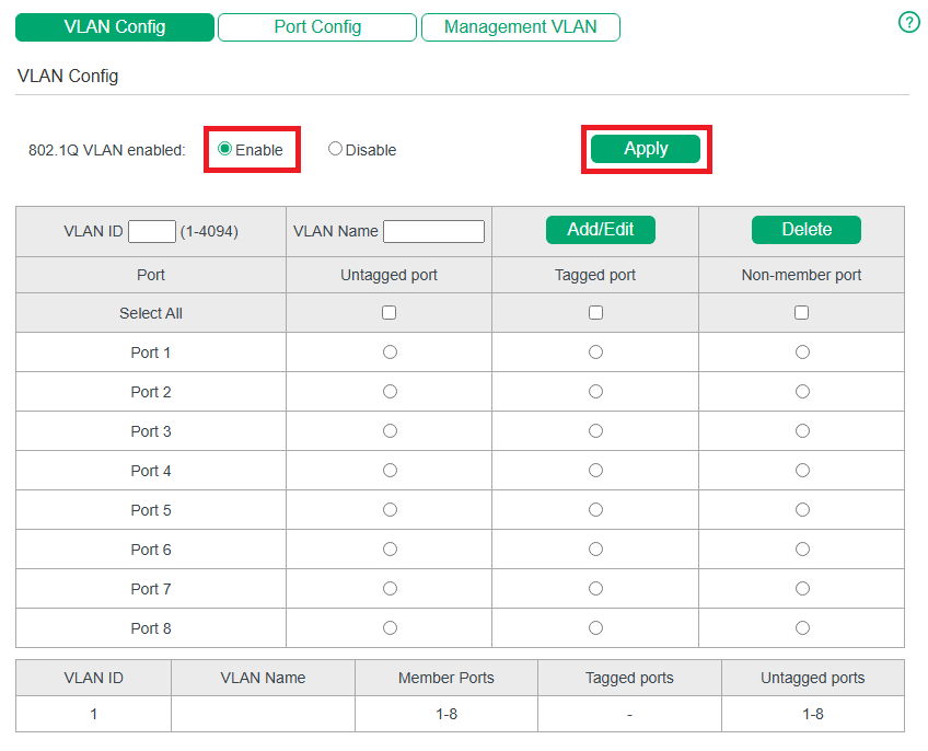
1) Select the 802.1Q VLAN configuration as Enable. Click Apply.
| 802.1Q VLAN enabled | Check the box to enable/disable the 802.1Q VLAN. |
|---|
2) Enter a VLAN ID and a VLAN name to identify the VLAN. Select the untagged port(s) and the tagged port(s) respectively to be added to the created VLAN based on the network topology. Click Add/Edit. To delete the VLAN created, enter the corresponding VLAN ID and click Delete.
| VLAN ID | Enter a VLAN ID, which ranges from 1 to 4094. |
|---|---|
| VLAN Name | Enter a VLAN name to identify the VLAN. The VLAN name only allows numbers, letters and underscores, and should not exceed 10 characters in length. |
| Untagged/ Tagged/ Non-member port |
Set the port as an untagged port, a tagged port or a non-member port in the VLAN. Untagged port: Click the checkbox to configure the egress rule of the traffic on this port as untagged. The switch drops the tag header before sending the packet. Tagged port: Click the checkbox to configure the egress rule of the traffic on this port as tagged. The switch adds the tag header before sending the packet. Non-member port: Click the checkbox to exclude the port from the current VLAN. |
3) In the table below, you can verify the configuration result of the 802.1Q VLAN.
| VLAN ID | Displays the ID number of VLAN. |
|---|---|
| VLAN Name | Displays the user-defined description of the VLAN. |
| Member Ports | Displays the member ports in the VLAN. |
| Tagged Ports | Displays the tagged member ports in the VLAN. |
| Untagged Ports | Displays the untagged member ports in the VLAN. |
|
Note: |
|---|
Configuring the PVID
Choose the menu VLAN > 802.1Q VLAN > Port Config to load the following page.
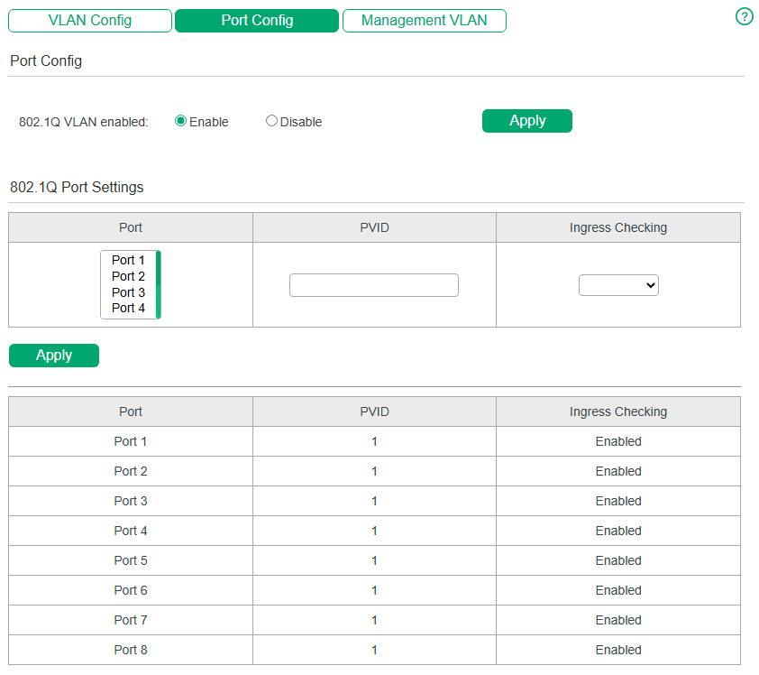
Follow these steps to configure the PVID:
1) Select the ports, set the PVID for the ports, and choose from the drop-down list to enable or disable Ingress Checking.
| PVID | Enter the default VLAN ID for the port. It can be added to the untagged packets as VLAN ID, and then the port will forward the packets in the corresponding VLAN. |
|---|---|
| Ingress Checking | Enable or disable Ingress Checking. With this function enabled, the port will accept the packet of which the VLAN ID is in the port’s VLAN list and discard others. With this function disabled, the port will forward the packet directly. |
2) Click Apply.
|
Note: |
|---|
Configuring Management VLAN
Choose the menu VLAN > 802.1Q VLAN > Management VLAN to load the following page.
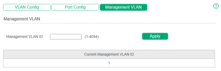
Follow these steps to configure the management VLAN:
1) Specify the management VLAN ID.
| Management VLAN ID | Enter a management VLAN ID, which should be within the range of the configured 802.1Q VLANs. After configuration, only PCs with management VLAN tags can access the management interface. Only one management VLAN ID can be configured for Easy Managed Switches. |
|---|
2) Click Apply.
|
Note: |
|---|
Configuration Example for 802.1Q VLAN
Network Requirements
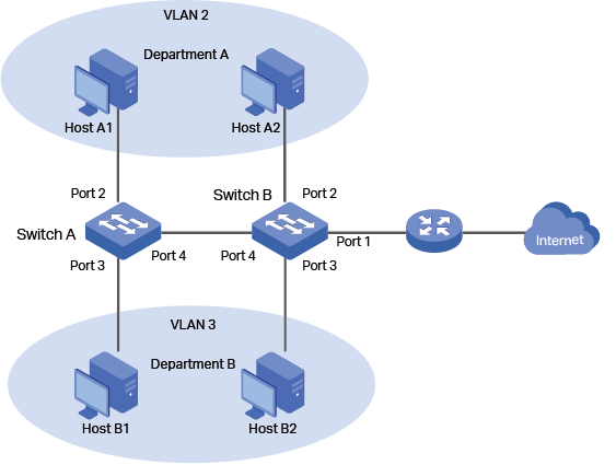
As the following figure shows, a company has two departments. Hosts of the same department are located in different places and connected to different switches respectively.
Requirements:
· Hosts of both departments can access the internet.
· Hosts of the same department can communicate with each other, but hosts of different departments cannot.
Configuration Scheme
To implement the above requirements, configure 802.1Q VLAN on both switches.
· Create VLAN 2. On Switch A, add port 2 and port 4 to VLAN 2, while on Switch B, add port 1, port 2 and port 4 to VLAN 2.
· Create VLAN 3. On Switch A, add port 3 and port 4 of Switch A to VLAN 3, while on Switch B, add port 1, port 3 and port 4 to VLAN 3.
· Configure the default VLAN 1 to make sure the router can communicate with all ports of the two switches.
The following tables show configurations of VLANs on each switch.
Relationships of Ports and VLANs on Switch A and Switch B:
| Switch | Ports in VLAN 1 | Ports in VLAN 2 | Ports in VLAN 3 |
|---|---|---|---|
| Switch A | 2, 3, 4 | 2, 4 | 3, 4 |
| Switch B | 1, 2, 3, 4 | 1, 2 ,4 | 1, 3, 4 |
Settings of Egress Rule and PVID on Switch A and Switch B:
| Switch | Ports in VLAN 1 | Ports in VLAN 2 | Ports in VLAN 3 |
|---|---|---|---|
| Switch A | 2 | Untagged | 2 |
| 3 | Untagged | 3 | |
| 4 | Tagged | 1 | |
| Switch B | 1 | Untagged | 1 |
| 2 | Untagged | 2 | |
| 3 | Untagged | 3 | |
| 4 | Tagged | 1 |
|
Note: |
|---|
Configuration Steps
Demonstrated with a specific model, the following section provides configuration steps. The configuration steps on both switches are similar. Here we take Switch A for example.
1) Choose the menu VLAN > 802.1Q VLAN > VLAN Config to load the following page. Select 802.1Q VLAN configuration as Enable. Click Apply.
2) Choose the menu VLAN > 802.1Q VLAN > VLAN Config to load the following page and create VLAN 2. Specify VLAN ID as 2, add port 2 to the VLAN as an untagged port, and add port 4 to the VLAN as a tagged port. Click Add/Edit. 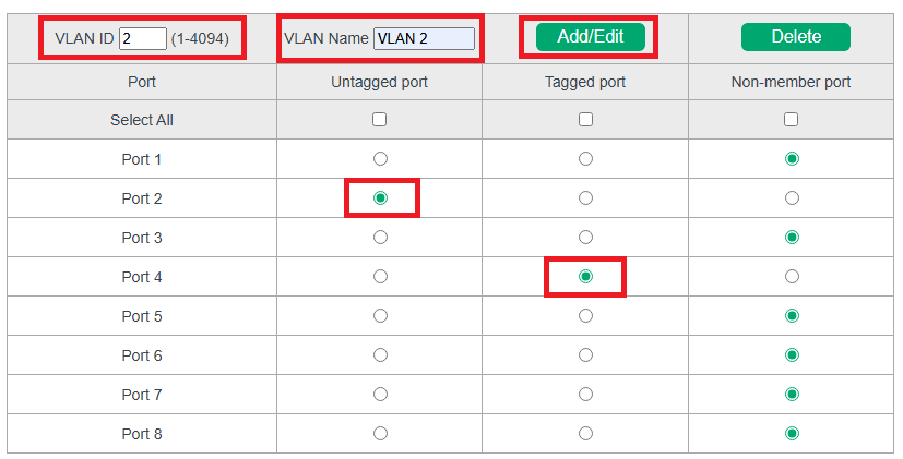
3) Choose the menu VLAN > 802.1Q VLAN > VLAN Config to load the following page and create VLAN 3. Specify VLAN ID as 3, add port 3 to the VLAN as an untagged port, and add port 4 to the VLAN as a tagged port. Click Add/Edit. 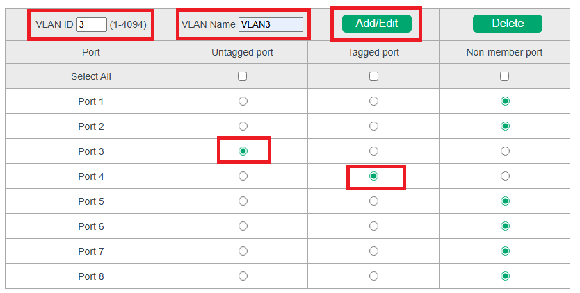
4) Choose the menu VLAN > 802.1Q VLAN > Port Config to load the following page. Specify the PVID of port 2 as 2 and click Apply. Specify the PVID of port 3 as 3 and click Apply.
Appendix: Default Parameters
Default Settings of VLAN Configuration are listed in the following:
| Parameter | Default Setting |
|---|---|
| MTU VLAN Configuration | Disable |
| Port Based VLAN Configuration | Enable |
| VLAN ID | 1 |
| 802.1Q VLAN Configuration | Disable |
| PVID | 1 |
| Management VLAN ID | 1 |
Configuring QoS
QoS
Overview
With network scale expanding and applications developing, internet traffic is dramatically increased, thus resulting in network congestion, packet drops and long transmission delay. Typically, networks treat all traffic equally on FIFO (First In First Out) delivery basis, but nowadays many special applications like VoD, video conferences, VoIP, etc. require more bandwidth or shorter transmission delay to guarantee the performance.
With QoS (Quality of Service) technology, you can classify and prioritize network traffic to provide differentiated services for certain types of traffic.
Supported Features
With the QoS feature, You can configure QoS Basic, Rate Limit and Storm Control on the switch to maximize the network performance and bandwidth utilization.
QoS Basic
QoS (Quality of Service) function is used to optimize the network performance. It provides you with network service experience of a better quality. The switch implements three priority modes based on port, 802.1p and DSCP.
Rate Limit
With a limited bandwidth, you can control the traffic rate on each port to ensure network in working order.
Storm Control
Storm Control function allows the switch to monitor broadcast packets, multicast packets and UL-frames (Unknown unicast frames) in the network. If the transmission rate of the packets exceeds the limit, the packets will be automatically discarded to avoid network broadcast storm.
Configuring Basic QoS
Configuration Guidelines
Select the QoS mode according to your network requirements. Three QoS modes are supported on the switch: Port-based, 802.1p-based and DSCP-based.
Port-Based
· The Port Priority function can classify the packets based on the ports that the packets reach, then map them to different queues.
Based on 802.1p
· 802.1p gives the Priority field in 802.1Q tag a recommended definition. The tagged packets are mapped to different priority levels based on 802.1Q tag.
Based on DSCP
· DSCP gives the IP DSCP field a recommended definition. The IP packets are mapped to different priority levels based on DSCP value.
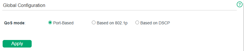
Configuring QoS in Port-Based Mode
Choose the menu QoS > QoS Basic to load the following page.
Follow these steps to configure QoS in port-based mode:
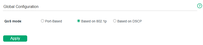
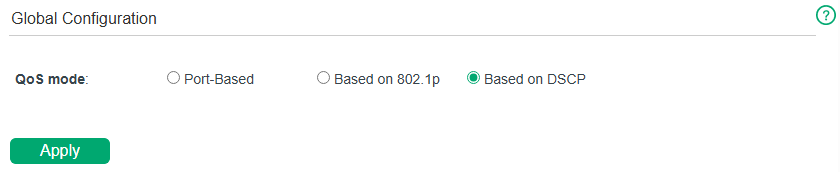
1) In the Global Configuration section, select QoS mode as Port-Based. Click Apply.

| QoS Mode | Select the QoS mode. |
|---|
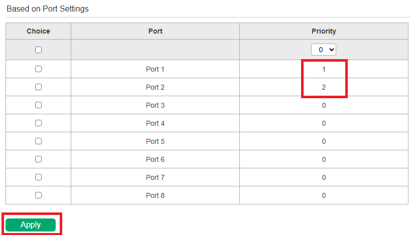
2) In the Based on Port Settings section, specify the mapping from Port to Priority. Click Apply.
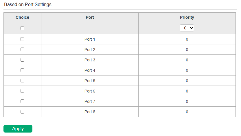
| Choice | Select the desired port for port priority configuration. |
|---|---|
| Port | Displays the physical port number of the switch. |
| Priority | Specify the priority for the port. |
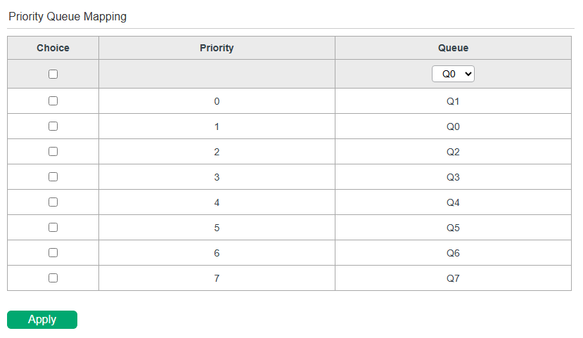
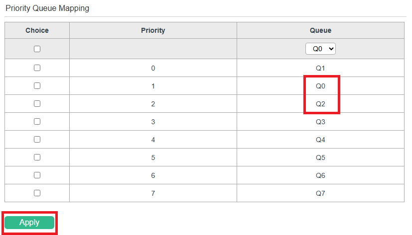
3) In the Priority Queue Mapping section, specify the mapping from Priority to Queue. Click Apply.

| Choice | Select the desired priority for queue configuration. |
|---|---|
| Priority | Displays the priority number. |
| Queue | Select the queue for the desired priority. |
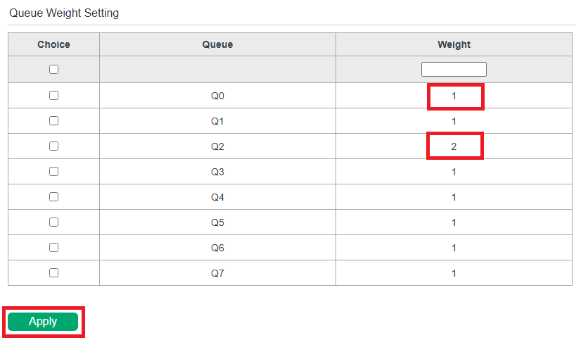
4) In the Queue Weight Setting section, specify the mapping from Queue to Weight. Click Apply.
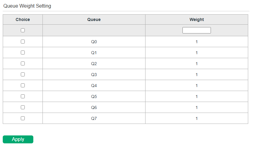
| Choice | Select the desired queue for weight configuration. |
|---|---|
| Queue | Displays the number of queue. |
| Weight | Specify the queue weight for the desired queue. The weight value identifies the bandwidth allocation ratio of different queues. Queues with higher weights will be assigned a larger proportion of bandwidth. |
Configuring QoS in 802.1p-Based Mode
Choose the menu QoS > QoS Basic to load the following page.
Follow these steps to configure QoS based on 802.1p:
1) In the Global Configuration section, select QoS mode as Based on 802.1p. Click Apply.
2) In the Priority Queue Mapping section, specify the mapping from Priority to Queue. Click Apply.
| Choice | Select the desired priority for queue configuration. |
|---|---|
| Priority | Displays the priority number. |
| Queue | Select the queue for the desired 802.1p priority. |
3) In the Queue Weight Setting section, specify the mapping from Queue to Weight. Click Apply.

| Choice | Select the desired queue for weight configuration. |
|---|---|
| Queue | Displays the ID number of priority Queue. |
| Weight | Specify the queue weight for the desired queue. The weight value identifies the bandwidth allocation ratio of different queues. Queues with higher weights will be assigned a larger proportion of bandwidth. |
Configuring QoS in DSCP-Based Mode
Choose the menu QoS > QoS Basic to load the following page.
Follow these steps to configure QoS based on DSCP:
1) In the Global Configuration section, select QoS mode as Based on DSCP. Click Apply.
2) In the Based on DSCP Settings section, specify the mapping from DSCP to Priority. Click Apply.
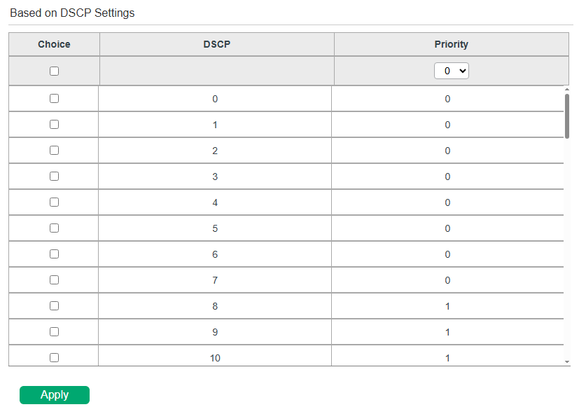
| Choice | Select the desired DSCP values for priority configuration. |
|---|---|
| DSCP | Displays the DSCP values. |
| Priority | Select the priority for the desired DSCP values. |
3) In the Priority Queue Mapping section, specify the mapping from Priority to Queue. Click Apply.
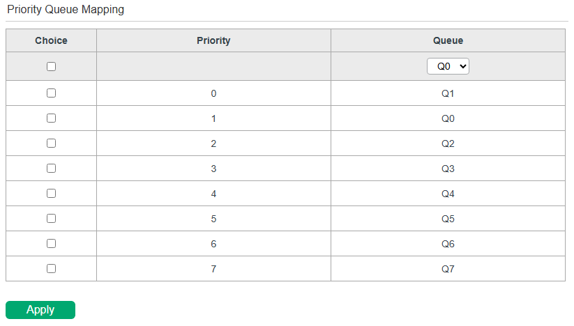
| Choice | Select the desired priority for queue configuration. |
|---|---|
| Priority | Displays the priority number. |
| Queue | Select the queue for the desired 802.1p priority. |
4) In the Queue Weight Setting section, specify the mapping from Queue to Weight. Click Apply.
| Choice | Select the desired queue for weight configuration. |
|---|---|
| Queue | Displays the ID number of priority Queue. |
| Weight | Specify the queue weight for the desired queue. The weight value identifies the bandwidth allocation ratio of different queues. Queues with higher weights will be assigned a larger proportion of bandwidth. |
Configuring Rate Limit
Choose the menu QoS > Rate Limit to load the following page.
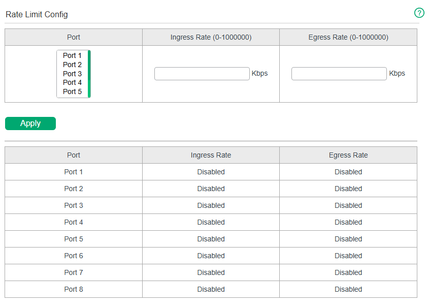
Follow these steps to configure rate limit:
1) To enable rate limit, select the desired ports and configure the ingress rate and egress rate for the ports. To disable the function, set the ingress rate and egress rate as 0 for the ports.
| Ingress Rate (Kbps) | Configure the bandwidth for receiving packets on the port. If the rate for receiving packets on the port exceeds the ingress rate, the packets will be discarded. |
|---|---|
| Egress Rate (Kbps) | Configure the bandwidth for sending packets on the port. If the rate for sending packets on the port exceeds the egress rate, the packets will be discarded. |
2) Click Apply.
|
Note: |
|---|
Configuring Storm Control
Choose the menu QoS > Storm Control to load the following page.
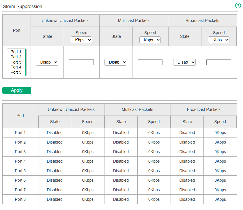
Follow these steps to configure storm control:
1) Select the desired ports and configure the upper rate limit for forwarding unknown unicast packets, multicast packets and broadcast packets.
| State | Enable or disable storm control on the port. |
|---|---|
| Speed | Specify the speed for the broadcast threshold, multicast threshold and unknown unicast frames threshold on the desired port. kbps: The switch will limit the maximum speed of the specific kinds of traffic in kilo-bits per second. pps: The switch will limit the maximum speed of the specific kinds of traffic in packets per second. |
| Unknown Unicast Packets | Specify the upper rate limit for receiving unknown unicast frames. The traffic exceeding the limit will be processed according to the Action configurations. |
| Multicast Packets | Specify the upper rate limit for receiving multicast packets. The multicast traffic exceeding the limit will be processed according to the Action configurations. |
| Broadcast Packets | Specify the upper rate limit for receiving broadcast packets. The broadcast traffic exceeding the limit will be processed according to the Action configurations. |
2) Click Apply.
|
Note: |
|---|
Configuration Example for Basic QoS
Network Requirements
As shown below, both RD department and Marketing department can access the internet. When congestion occurs, the traffic from two departments can both be forwarded and the traffic from the Marketing department should take precedence.
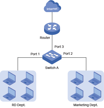
Configuration Scheme
To implement this requirement, you can configure QoS in port-based mode to put the packets from the Marketing department into the queue with the higher weight than the packets from the RD department. Follow these procedures to configure QoS in port-based mode.
1) Enable port-based mode.
2) Map port 1 and port 2 to different weight.
Demonstrated with a specific model, the following section provides configuration steps.
Configuration Steps
1) Choose the menu QoS > QoS Basic to load the following page. In the Global Configuration section, select QoS mode as Port-based. Click Apply.
2) In the Based on Port Settings section, specify the Priority for Port 1 as 1 and the Priority for Port 2 as 2. Click Apply.
3) In the Priority Queue Mapping table, specify the Queue for Priority 1 as Q0 and the Queue for Priority 2 as Q2. Click Apply.
4) In the Queue Weight Setting table, specify the Weight for Queue Q0 as 1 and the Weight for Queue Q2 as 2. Click Apply.
Appendix: Default Parameters
Default settings of QoS Basic configuration are listed in the following table.
| Parameter | Default Setting |
|---|---|
| QoS Mode | Port-Based |
Default settings of Rate Limit configuration are listed in the following table.
| Parameter | Default Setting |
|---|---|
| Ingress Rate (Kbps) | Unlimited |
| Egress Rate (Kbps) | Unlimited |
Default settings of Storm Control configuration are listed in the following table.
| Parameter | Default Setting |
|---|---|
| Status | Disable |
| Speed | Unlimited |
Monitoring
Monitoring
Overview
With the Monitoring feature, you can monitor the traffic on the switch.
Supported Features
Traffic Summary
Traffic Summary displays the traffic information of each port, which facilitates you to monitor the traffic and analyze the network abnormity.
Mirroring
Mirroring refers to the process of forwarding copies of packets from one port to a mirroring port. Usually, the mirroring port is connected to a data diagnose device, which is used to analyze the mirrored packets for monitoring and troubleshooting the network.
Cable Test
Cable Test functions to test the cable connection status, length and error length when the cable is connected to the port of the switch, which facilitates you to locate and diagnose the trouble spot of the network.
Loop Detection
Loop Dectection is used to detect the loop created by a specific port.
Viewing Traffic Summary
Choose the menu Monitoring > Traffic Summary to load the following page.
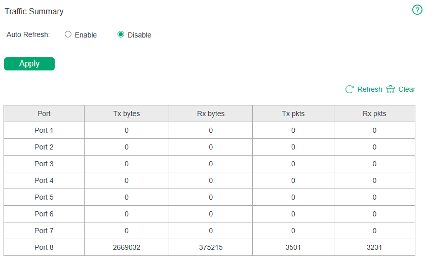
You can choose to enable or disable Auto Refresh and click Apply.
| Auto Refresh | With this option enabled, the switch will automatically refresh the traffic summary every 10 seconds. |
|---|
You can view the statistics of each port. You can click Refresh to refresh the data and click Clear to clear the data.
| Port | Displays the port number of the switch. |
|---|---|
| Tx bytes | Displays the number of octets transmitted on the port. Error packets are counted. |
| Rx bytes | Displays the number of octets received on the port. Error packets are counted. |
| Tx pkts | Displays the number of packets transmitted on the port. |
| Rx pkts | Displays the number of packets received on the port. |
|
Note: |
|---|
Configuring Mirroring
Choose the menu Monitoring > Mirroring to load the following page.
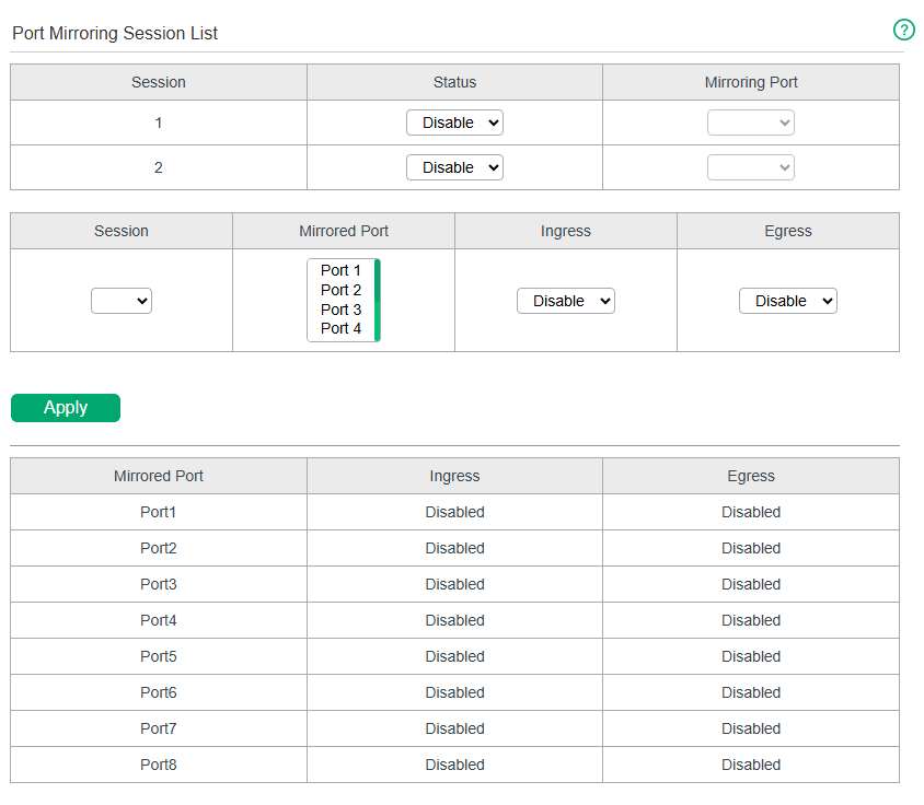
Follow these steps to configure mirroring:
1) Enable the port mirror feature globally. Specify a mirroring port. Click Apply.
| Session | Displays the session number. |
|---|---|
| Status | Select to enable/disable the port mirror feature. |
| Mirroring Port | Select a port from the drop-down list as the mirroring port. |
2) Select one or more mirrored ports, enable or disable the ingress packets and egress packets to be mirrored for the ports. Click Apply.
| Mirrored Port | Select one or multiple desired port(s) as the mirrored port(s). |
|---|---|
| Ingress | Select to enable/disable the Ingress feature. When the Ingress is enabled, the incoming packets received by the mirrored port will be copied to the mirroring port. |
| Egress | Select to enable/disable the Egress feature. When the Egress is enabled, the outgoing packets sent by the mirrored port will be copied to the mirroring port. |
3) In the table below, you can verify the configuration result for port mirroring.
|
Note: |
|---|
Testing Cables
Choose the menu Monitoring > Cable Test to load the following page.
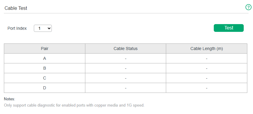
Follow these steps to diagnose the cable:
1) Select a desired port for test. Click Test to test cables connected to the selected port.
| Port Index | Select the port for cable testing. |
|---|
2) Check the test results in the table.
| Pair | Displays the cable pairs. |
|---|---|
| Cable Status | Displays the cable test results. |
| Cable Length | If the connection status is Normal, here displays the length of the cable. If the connection status is Close (or Short), Open or Crosstalk, here displays the length from the port to the trouble spot. |
|
Note: Cable diagnostic is only supported for 1G speed. |
|---|
Configuring Loop Prevention
Choose the menu Monitoring > Loop Detection to load the following page.
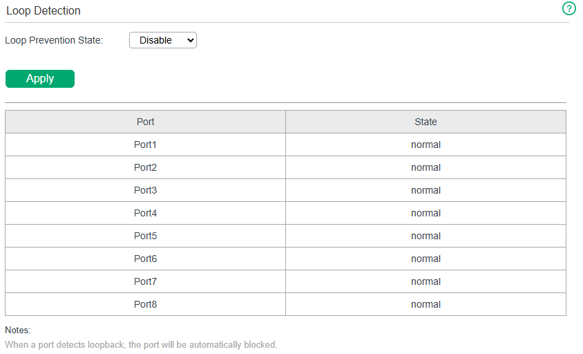
Follow these steps to configure loop prevention:
1) Enable or disable loop prevention. Click Apply.
| Loop prevention state | Enable or disable the loop prevention feature. |
|---|
2) In the table below, you can check the state of each port.
| Port | Displays the physical port number of the switch. |
|---|---|
| State | Displays the port status. |
|
Note: |
|---|
Appendix: Default Parameters
Default settings of Traffic Summary are listed in the following table.
| Parameter | Default Setting |
|---|---|
| Auto Refresh | Disable |
Default settings of Mirroring are listed in the following table.
| Parameter | Default Setting |
|---|---|
| Mirroring Status | Disable |
| Ingress | Disable |
| Egress | Disable |
Default settings of Cable Test are listed in the following table.
| Parameter | Default Setting |
|---|---|
| Port Index | 1 |
Default settings of Loop Prevention are listed in the following table.
| Parameter | Default Setting |
|---|---|
| Loop prevention state | Disable |
System Tools
System Tools
Overview
In System Tools module, you can upgrade the firmware, back up and restore configuration, reset and reboot the switch.
Supported Features
System Upgrade
The switch system can be upgraded to get more functions and better performance.
Backup Restore
The switch configuration can be backed up and saved as a file to your computer, and restored later.
System Reset
The switch can be reset to factory settings.
System Reboot
The switch can be manually rebooted.
Upgrading the Firmware
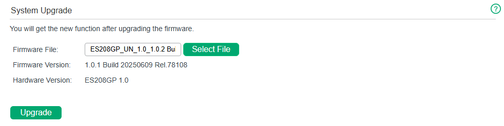
Choose the menu System Tools > System Upgrade to load the following page.
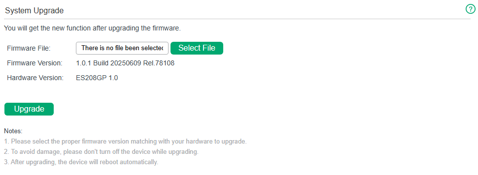
Follow these steps to upgrade the firmware:
1) Click Select File to load the following page. Specify the firmware file path and select the firmware to upgrade.
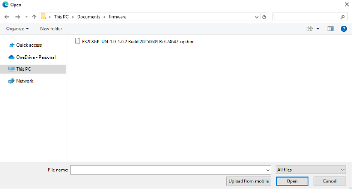
2) Click Open and the following page will be displayed. Click Upgrade.
|
Note: |
|---|
Backing up and Restoring the Switch
With backup and restore, you can:
· Save the current configuration.
· Restore to the previous configuration.
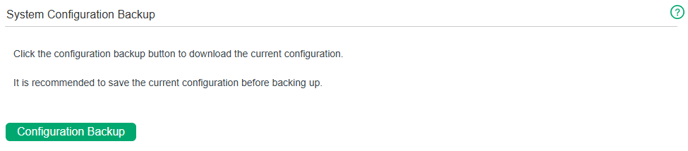
Saving the Current Configuration
Choose the menu System Tools > Backup Restore to load the following page. In the System Configuration Backup section, click Configuration Backup to save the configuration file to your PC.
|
Note: |
|---|
Restoring to the Previous Configuration
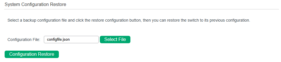
Choose the menu System Tools > Backup Restore to load the following page.
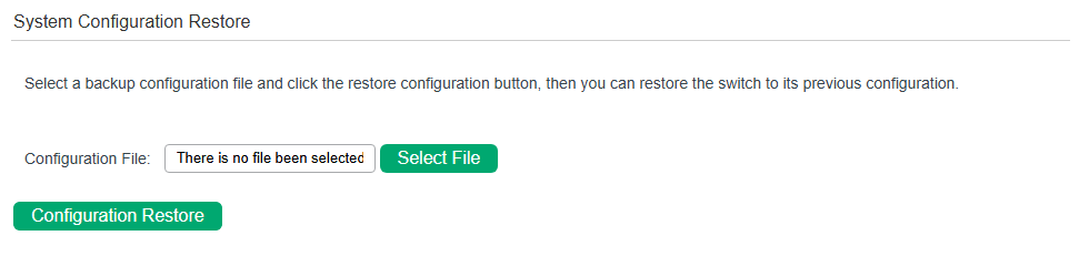
Follow these steps to restore the switch to the previous configuration:
1) In the System Configuration Restore section, click Select File to load the following page. Specify the configuration file path and select the configuration file.
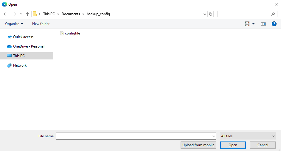
2) Click Open and the following page will be displayed. In the System Configuration Restore section, click Configuration Restore to restore the switch to the previous configuration. It will take effect after the switch automatically reboots.
|
Note: |
|---|
Resetting the Switch
Choose the menu System Tools > System Reset to load the following page.
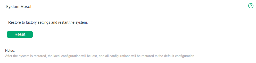
Follow these steps to reset the switch.
1) Click Reset, and the following page will pop up.
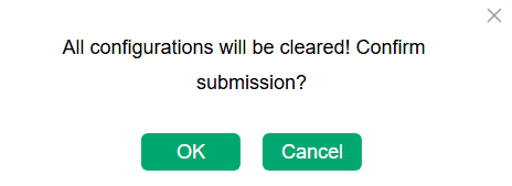
2) Click OK to reset the switch.
|
Note: |
|---|
Rebooting the Switch
Choose the menu System Tools > System Reboot to load the following page. Click Reboot.
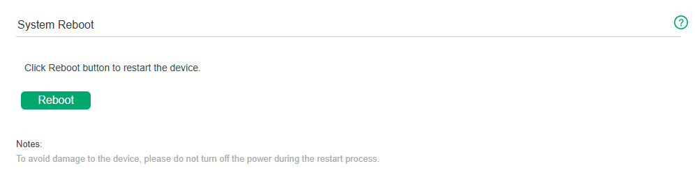
|
Note: |
|---|
Configuring EEE
EEE
Overview
Energy Efficient Ethernet (EEE) is used to reduce the power consumption of the switch during periods of low data transmission.
Supported Features
EEE Config
You can simply enable this feature on ports to allow power reduction. If the port is a member port of an LAG, it will follow the EEE configuration of the LAG and not its own.
Configuring EEE
Choose the menu EEE > EEE to load the following page.
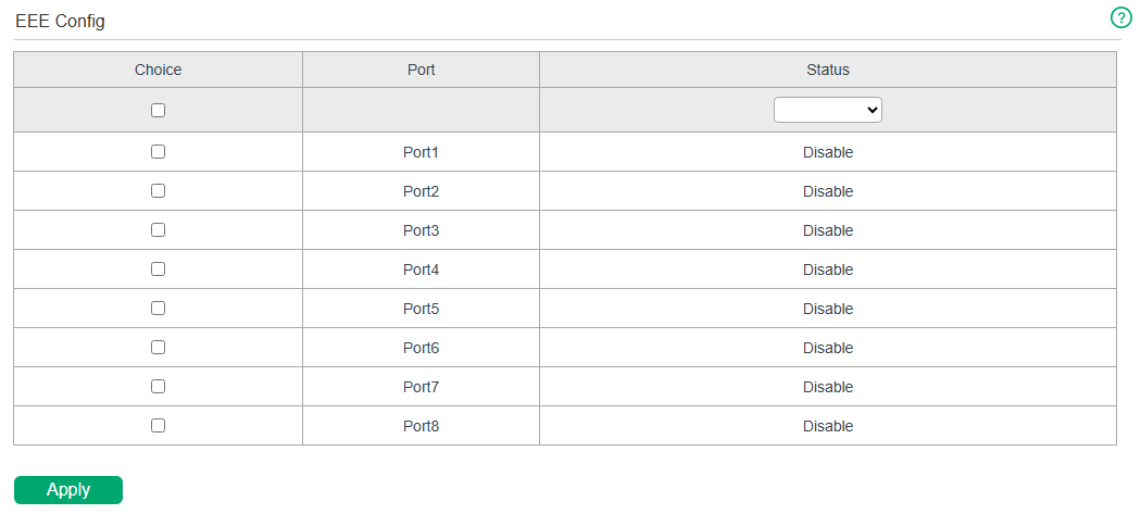
Follow these steps to configure EEE:
1) Select one or more ports to enable or disable EEE.
| Port |
Select one or more ports to configure. |
|---|---|
| Status |
Enable or disable EEE on the selected port(s). |
2) Click Apply.
Configuring PoE (Only for Certain Models)
PoE
Overview
PoE (Power over Ethernet) is an implementation of power supply of PD (Powered Device) linked to the PoE switch through the RJ-45 port. It is a mechanism which implements power supply and data transmission synchronously.
In the PoE module, you can configure basic settings, PoE auto recovery, and extend mode for the PoE ports of the switch.
|
Note: |
|---|
Supported Features
PoE Config
You can configure the general PoE settings for the switch as well as the PoE parameters for each port.
PoE Auto Recovery
PoE Auto Recovery uses ping packets to detect the link status between PoE ports and connected PoE powered devices (PDs). The switch pings the IP addresses of PDs constantly. If a PD loses connection, the switch will reboot it automatically.
PoE Extend Mode
Extend Mode can increase the transmission distance to support long-distance wiring. When enabled, it extends the maximum transmission distance from 100 m to 250 m but limits the maximum speed to 10 Mbps.
Configuring PoE
Choose the menu PoE > PoE Config to load the following page.
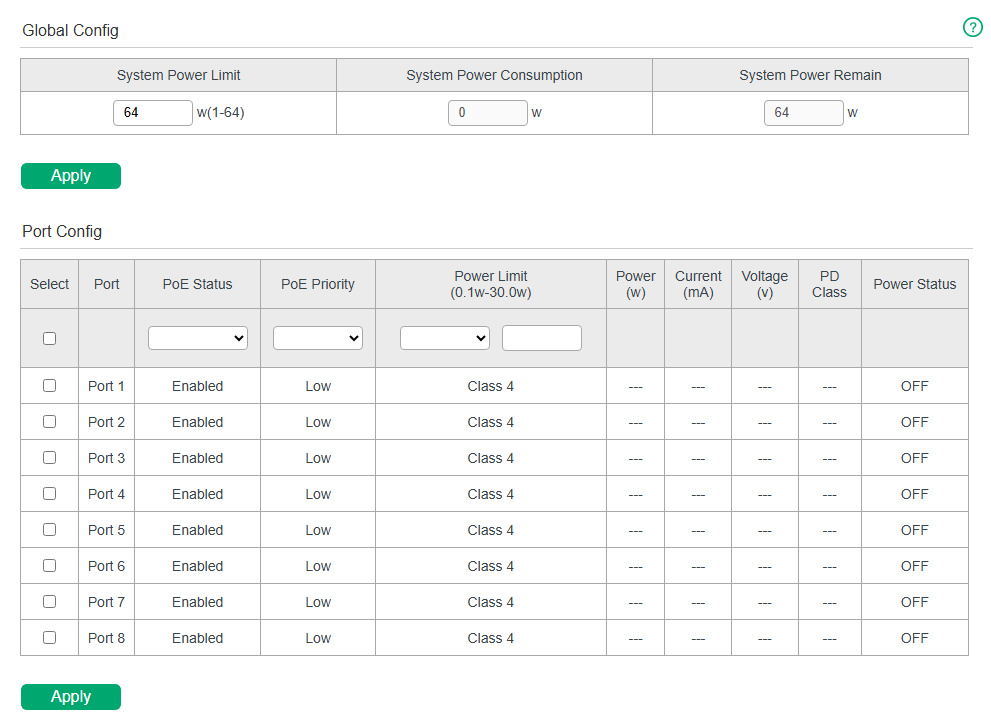
Follow these steps to configure PoE:
1) In the Global Config section, you can view the current PoE parameters. You can configure the System Power Limit. Click Apply.
| System Power Limit | Specify the maximum power the PoE switch can supply. |
|---|---|
| System Power Consumption | Displays the real-time system power consumption of the PoE switch. |
| System Power Remain | Displays the real-time system remaining power of the PoE switch. |
2) In the Port Config section, select the ports you want to configure and specify the parameters. Click Apply.
| PoE Status | Enable or disable the PoE function on corresponding ports. A port can supply power to the PD when its status is enable. |
|---|---|
| PoE Priority | Select the priority level (High, Middle, Low) for the corresponding port. When the supply power exceeds the system power limit, the switch will power off PDs on low-priority ports to ensure stable running of other PDs. |
| Power Limit (0.1 w-30 w) |
Specify the maximum power the corresponding port can supply. The following options are provided: Auto: The maximum power that the port can supply will be adjusted automatically. Class 1: The maximum power that the port can supply is 4 W. Class 2: The maximum power that the port can supply is 7 W. Class 3: The maximum power that the port can supply is 15.4 W. Class 4: The maximum power that the port can supply is 30 W. Manual: You can enter a value manually. |
| Power (w) | Displays the real-time power supply of the port. |
| Current (mA) | Displays the real-time current of the port. |
| Voltage (v) | Displays the real-time voltage of the port. |
| PD Class | Displays the class which the linked PD belongs to. |
| Power Status | Displays the real-time power status of the port. |
Configuring PoE Auto Recovery
Choose the menu PoE > PoE Auto Recovery to load the following page.
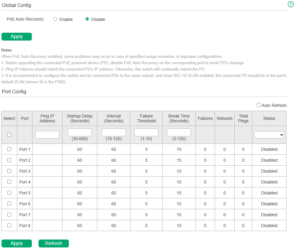
Follow these steps to enable PoE Auto Recovery and configure the parameters:
1) In the Global Config section, enable or disable PoE Auto Recovery. Click Apply.
| PoE Auto Recovery | Enable or disable PoE Auto Recovery globally. |
|---|
2) In the Port Config section, select the desired ports and specify the parameters. Click Apply.
| Auto Refresh | When Auto Refresh is enabled, the switch refreshes the data every 5 seconds so you can get the real-time ping statistics. |
|---|---|
| Ping IP Address |
Enter the IP address of the PD connected to the port. Ping IP Address should be the same as the connected PD’s IP address. Otherwise, the switch will continually reboot the PD. |
| Startup Delay | Specify how long the switch waits for the connected PD’s rebooting before the switch starts to ping the PD’s IP address. It ranges from 30 to 600 seconds. |
| Interval | Specify the interval between two consecutive ping packets. It ranges from 10 to 120 seconds. |
| Failure Threshold | Specify the threshold for ping failures. If the switch fails to get the ping response from the PD on the port, the switch will retry until the number of ping failures reaches the threshold, and then the switch will reboot the PD. It ranges from 1 to 10. |
| Break Time | Specify how soon the switch reboots the PD after the number of ping failures reaches the threshold. It ranges from 3 to 120 seconds. |
| Failures | Display the number of ping failures since the latest reboot of the PD. It will be reset when the PD responds to the ping packet or is rebooted. |
| Reboots | Display the number of PD’s reboots. It will be reset after reaching 9,999 or when the switch is rebooted. |
| Total Pings | Display the total number of ping packets that the switch sends to the connected PD. It will be reset after reaching 9,999 or when the switch is rebooted. |
| Status | Enable or disable PoE Auto Recovery on the desired ports. To make it enabled, enable PoE Auto Recovery both globally and on the port. |
|
Note: |
|---|
Configuring PoE Extend Mode
Choose the menu PoE > PoE Extend Mode to load the following page.
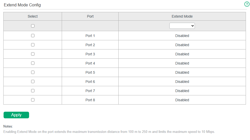
Follow these steps to enable Extend Mode and configure the parameters:
1) In the Extend Mode Config section, select the desired ports and choose from the drop-down list to enable or disable Extend Mode .
| Extend Mode | Select to enable/disable Extend Mode on the desired port. |
|---|
2) Click Apply.
|
Note: |
|---|
Appendix: Default Parameters
Default settings of PoE are listed in the following table.
| Parameter | Default Setting |
|---|---|
| PoE Status | Enabled |
| PoE Priority | Low |
| Power Limit | Class 4 |
Default settings of PoE Auto Recovery are listed in the following table.
| Parameter | Default Setting |
|---|---|
| PoE Auto Recovery | Disable |
| Ping IP Address | Null |
| Startup Delay | 60 seconds |
| Interval | 60 seconds |
| Failure Threshold | 5 |
| Break Time | 15 seconds |
| Status | Disabled |
Default settings of Extend Mode are listed in the following table.
| Parameter | Default Setting |
|---|---|
| Extend Mode | Disabled |
Controller Settings
Controller Settings
Overview
With the Controller Settings module, you can enable the switch to be discovered and then be managed centrally by the Omada Controller.
Supported Features
Cloud-Based Controller Management
By enabling Cloud-Based Controller Management, you can configure your switch via the Omada Cloud-Based Controller and enjoy centralized management.
Controller Inform URL
By entering the Inform URL/IP Address of the controller, you can allow the switch to be discovered by the controller via this address.
Configuring Controller Settings
Choose the menu Controller Settings > Controller Settings to load the following page.
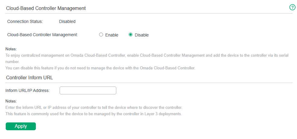
Follow these steps to configure controller settings:
1) Select Cloud-Based Controller Management as Enable. Click Apply.
| Connection Status |
Displays the status of the connection between the switch and the Omada Cloud-Based Controller. Disabled: Cloud-Based Controller Management is disabled. Online: The switch is connected to the Omada Cloud and not managed by the Cloud-Based Controller yet. Offline: The switch is not connected to the Omada Cloud. |
|---|---|
| Cloud-Based Controller Management |
Enable or disable Omada Cloud-Based Controller Management. With this feature enabled, the switch can communicate with the Omada Cloud Platform. |
2) Specify the inform URL or IP address of the controller. Click Apply.
| Inform URL/IP Address |
Enter the inform URL or IP address of your controller to tell the switch where to discover the controller. |
|---|
|
Note: |
|---|
Appendix: Default Parameters
Default settings of Controller Settings are listed in the following table.
| Parameter | Default Setting |
|---|---|
| Cloud-Based Controller Management | Disable |
| Inform URL/IP Address | Null |
