


The images in this guide are for demonstration only and may differ from your actual product.
1 Installation
Desktop Installation
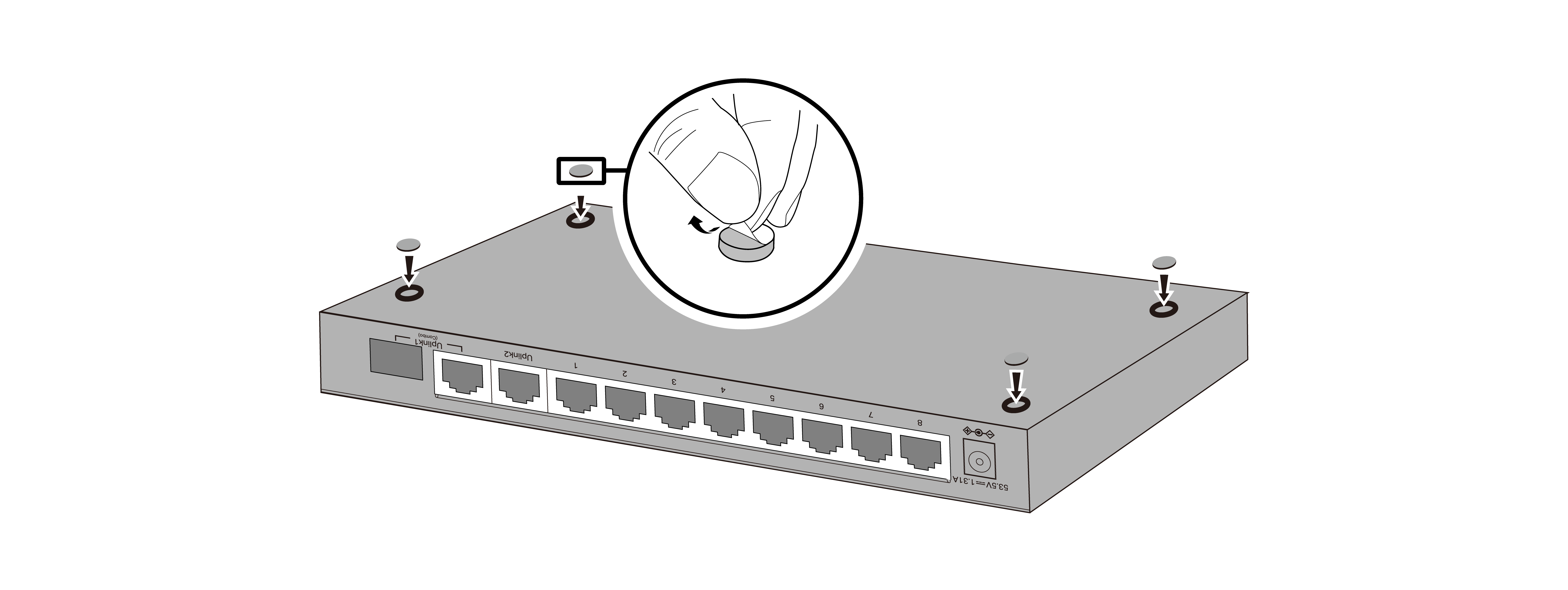
Attach the supplied rubber feet to the bottom of the switch to prevent it from slipping when placed on a desktop.
Wall-Mounting Installation
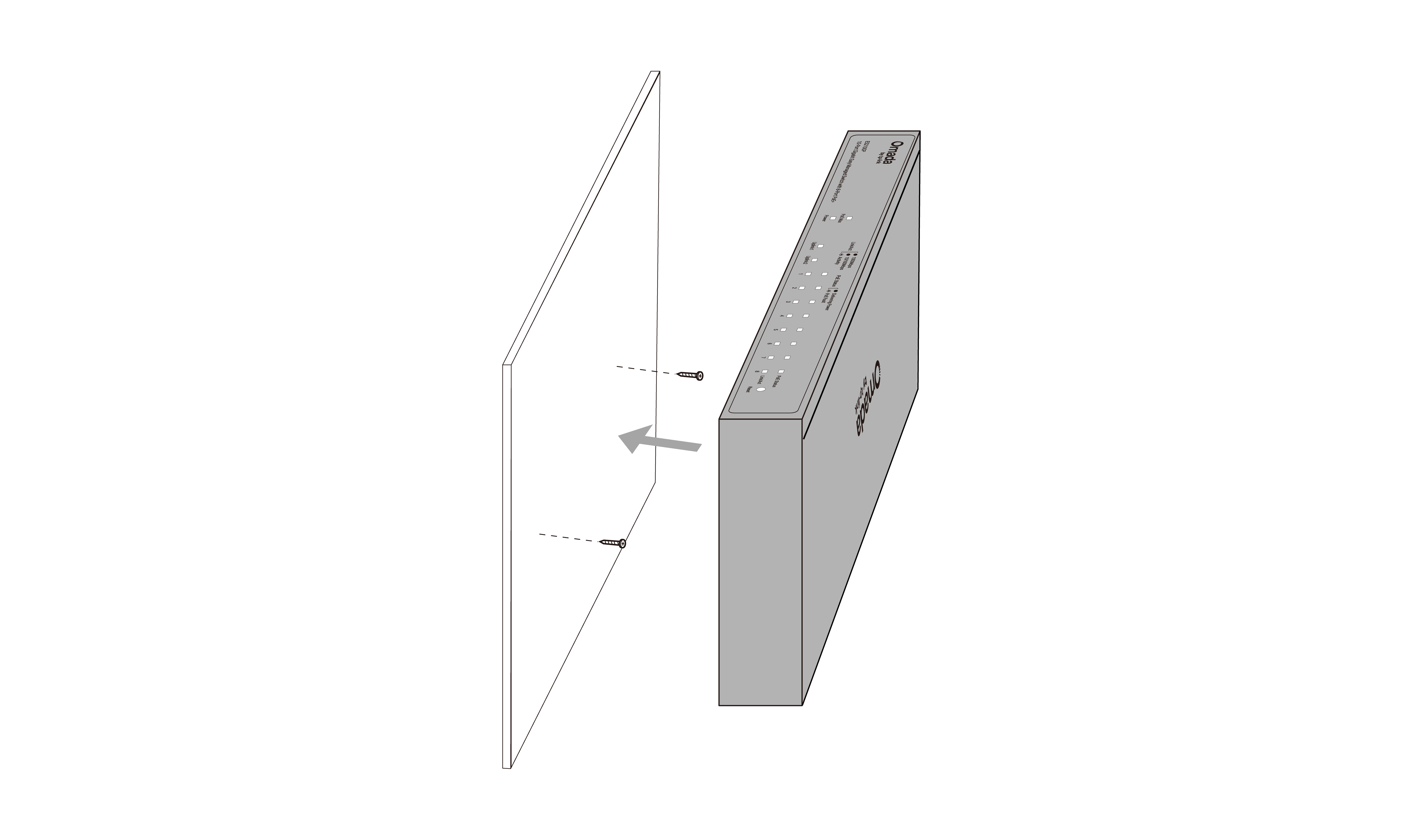
Drill two holes on the wall according to the mounting holes on the bottom of the switch, then secure the switch to the wall with two suitable screws (not provided).
Note:
For detailed information, please refer to the Wall Mounting Guide.
2 Connection
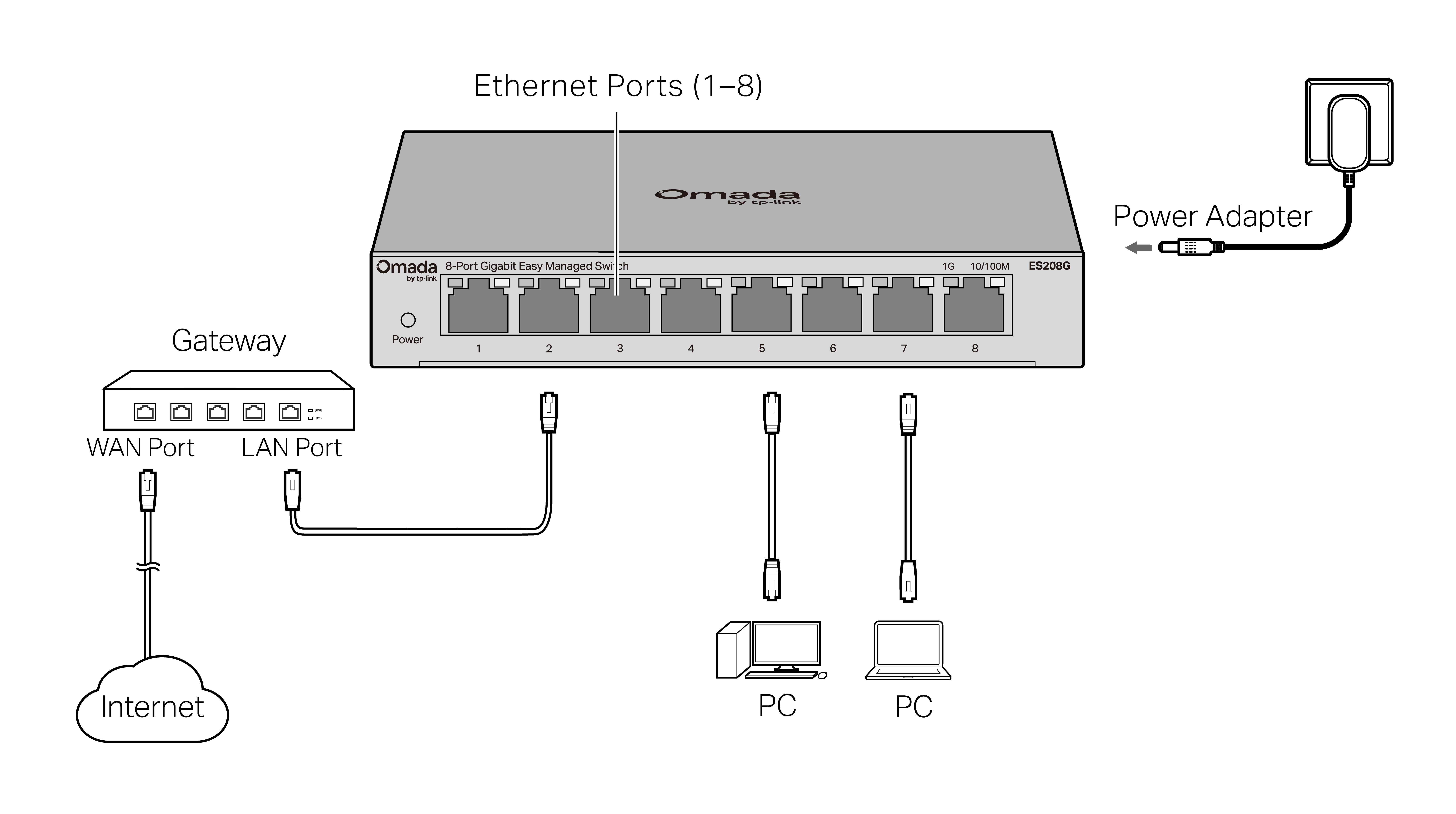
Connection for Non-PoE Switch
For simplicity, we will take ES208G for example.
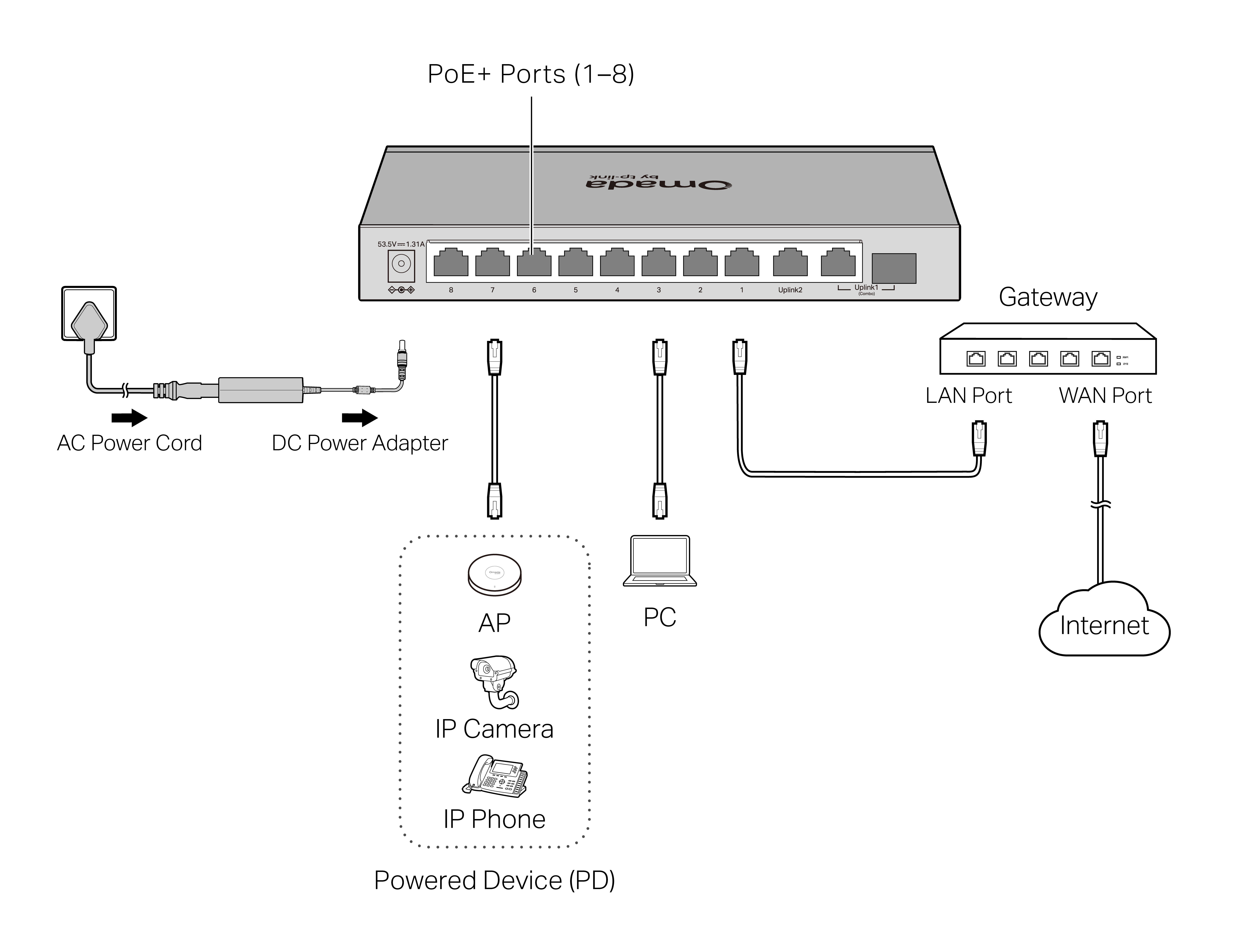
Connection for PoE Switch
For simplicity, we will take ES210GP for example.
Note:
1. The PoE ports can also connect to non-PoE devices, but only transmit data.
2. The PoE ports shall not be used to charge lithium batteries or devices supplied by lithium batteries.
3. The uplink ports typically connect to uplink devices like routers/gateways.
4. The combo port consists of one RJ45 port and one SFP slot, which cannot be used simultaneously.
5. The SFP slot needs to work with a gigabit SFP module.
3 Configuration
The switch supports two configuration methods:
· Standalone Mode: Configure and manage the switch individually. To set up a standalone Omada switch, refer to https://www.omadanetworks.com/support/faq/4097/.
· Controller Mode: Configure and manage the network devices centrally. This mode is recommended for large-scale networks with numerous devices, including access points, switches, and gateways. To set up an Omada switch with an Omada Controller, refer to the Omada Controller configuration guide at https://www.omadanetworks.com/support/faq/4096/.
Omada App
With the TP-Link Omada app, you can access and manage your Omada devices at a local site or remotely with a tap of your phone. You can download and install the TP-Link Omada app from the App Store or Google Play.


For detailed instructions on device configuration, refer to the user guides of the Controller and switches. The guides can be found in the support center of our official website: https://support.omadanetworks.com/document/.
4 LED Explanation
| Power | On/Off: Power on/off |
|---|---|
| Link/Act | On (Green): Running at 1000 Mbps On (Yellow): Running at 10/100 Mbps Flashing: Transmitting/receiving data Off: No connected device |
|
Uplink1, Uplink2 (Only ES210GP/ES210GMP have the uplink ports) |
|
| PoE Status (For ES205GP/ ES206GP/ ES208GP/ ES210GP/ ES210GMP) |
On: Providing PoE power Flashing: PoE fault Off: Not providing PoE Power |
| PoE Max (For ES205GP/ ES206GP/ ES208GP/ ES210GP/ ES210GMP) |
On: The remaining PoE power is ≤ 7 W Flashing: The remaining PoE power keeps ≤ 7 W after this LED is on for 2 minutes Off: The remaining PoE power is > 7 W |
5 Environmental and Physical Specifications
| Operating Temperature | -5 ˚C to 40 ˚C (32 ˚F to 104 ˚F) (For ES206GP) -5 ˚C to 45 ˚C (23 ˚F to 113 ˚F) (For ES208G) 0 ˚C to 40 ˚C (32 ˚F to 104 ˚F) (For other switches) |
|---|---|
| Storage Temperature | -40 ˚C to 70 ˚C (-40 ˚F to 158 ˚F) |
| Operating Humidity | 10% RH to 90% RH non-condensing |
| Storage Humidity | 5% RH to 90% RH non-condensing |
6 Frequently Asked Questions (FAQ)
Q1. The Power LED is not lit.
The Power LED should be lit when the power system is working normally. If the Power LED is not lit, please check as follows:
A1: Make sure the switch and power source are properly connected through the power adapter.
A2: Make sure the power source voltage meets the input voltage requirements of both the power adapter and the switch.
A3: Make sure the power source is on.
Q2. Why is the Link/Act LED not lit while a device is connected to the corresponding port?
It is recommended that you check the following items:
A1: Make sure that the cable connectors are firmly plugged into the switch and the device.
A2: Make sure the connected device is turned on and working well.
A3: The cable must be less than 100 meters long (328 feet). If Extend Mode is enabled, it should be less than 250 meters (820 feet).
Q3. Why is PoE Port not supplying power for PoE devices?
When the total power consumption of connected PoE devices exceeds the maximum, the PoE port with a smaller port number has a higher priority. The system will cut off power to the ports with larger port numbers to ensure supplying to other ports.
Take ES205GP for example. If port 1, 2 and 4 are consuming 15.4 W respectively, and an additional PoE device with 20 W is connected to port 3, the system will cut off the power of port 4 to compensate for the overload.
