


What is M-LAG and How to Configure M-LAG on Omada Switch from Omada Pro Network System


Contents
Configuration for M-LAG System Handling Layer 2 Forwarding Only
Configuration for M-LAG System Handling Layer 3 Forwarding
Introduction
M-LAG is short for Multi-Chassis Link Aggregation Group, also known as MC-LAG, it is a mechanism designed to achieve LAG across the devices.
When operating M-LAG, the two devices involved logically function as a single entity for traffic forwarding. In terms of loop prevention and device redundancy, it delivers effects comparable to stacking, enabling both link redundancy through bundling and redundancy against single-point device failures. However, it differs significantly from stacking: in a stacking system, all the units’ control are merged on the master unit alone but in an M-LAG system, the control of the two devices remains independent, thereby preventing a single point of failure from impacting the entire system.
Moreover, stacking often results in prolonged packet loss due to upgrades (which require a holistic system-wide upgrade) or replacements. In contrast, M-LAG allows for individual traffic switching on the two devices, followed by sequential upgrades or replacements, ensuring business continuity throughout the process. As the campus network devices require higher standards, with increasingly stringent requirements for business interruption time and network reliability, M-LAG is essential to provide efficient and reliable virtualization capabilities.
Before we go to the detailed configuration of M-LAG, the following key terms and their definitions should be introduced and understood in advance:
- Peer Device: The two switches operating the same M-LAG are called peer devices. Unlike stacking, when operating normally, the two switches are the same on role, no significant “master” or “member”, that’s why they are called peer devices.
- M-LAG Domain: The domain of M-LAG, including the dual-active system formed by two peer switches and the link transmitting negotiation or control message between them.
- Peer-Link: The direct link connecting two M-LAG peer switches within the M-LAG Domain, responsible for exchanging M-LAG controlling information, synchronizing table entries and transmitting part of the forwarded service traffic.
- DAD: Short for Dual-Active Detection, it is a mechanism designed to identify and mitigate "dual-active" scenarios, where both M-LAG peer devices mistakenly operate as active due to a failure in the peer-link or synchronization. When the peer-link fails, the two peers fail to synchronize and the M-LAG system will split, it could cause chaos in the network if the two peers keep running without synchronizing with each other, with DAD, it could detect if the M-LAG peer switch is still alive after splitting or the so called “brain-splitting” and shut one of the peer’s M-LAG operation down to keep the traffic forwarding clear in the M-LAG domain.
- DAD-Link: The direct link connecting two M-LAG peer switches to perform DAD, it is a pure IP based detection, so the ports involving DAD-link will act as routed ports.
- M-LAG Member Port: The ports on M-LAG peer devices connect to clients and form the LAG between clients and M-LAG peer devices.
- Orphan Port: The ports or LAGs which are not configured as M-LAG member ports. Connecting to an orphan port will not join the traffic to M-LAG system, the redundancy cannot be ensured.
- Dual-Homed Access: The connecting method where client device connects to both M-LAG peer devices within the M-LAG domain and form LAG across peer devices.
- Single-Homed Access: The connecting method where client device connects to only one M-LAG peer device within the M-LAG domain and not forming LAG across peer devices. The redundancy of single-homed devices cannot be ensured.
Please bear in mind that in M-LAG deployments, the peer-link primarily facilitates the synchronization of dynamic table entries, such as MAC address tables, ARP tables, and other runtime state information to ensure consistent traffic forwarding and loop prevention across the M-LAG peer devices. However, M-LAG does not automatically synchronize configurations between the peers. Therefore, to achieve operational consistency for M-LAG related features, identical configurations must be manually applied on both M-LAG peer devices. Note that this requirement applies only to specific M-LAG-relevant settings—such as peer-link interfaces, LAG or LACP parameters, global and port IGMP snooping status, and redundancy protocols. It’s not to the entire switch configuration, which is allowing independent management of unrelated features on each device.
Requirements
- Omada S6500 and S7500 Series Switch
- Omada Pro Network System v6.1 and above
Configuration
In the following section, we will give a simple example about the configuration of M-LAG on Omada S6500 and S7500 switches when adopted on Omada Pro Network System. The configuration will be given based on two scenarios:
The first scenario is that the M-LAG system will not handle layer 3 forwarding or IP forwarding, only providing layer 2 forwarding and redundancy.
The second scenario is that the M-LAG system will handle layer 3 forwarding or IP forwarding, providing both layer 2 and layer 3 redundancy.
Configuration for M-LAG System Handling Layer 2 Forwarding Only
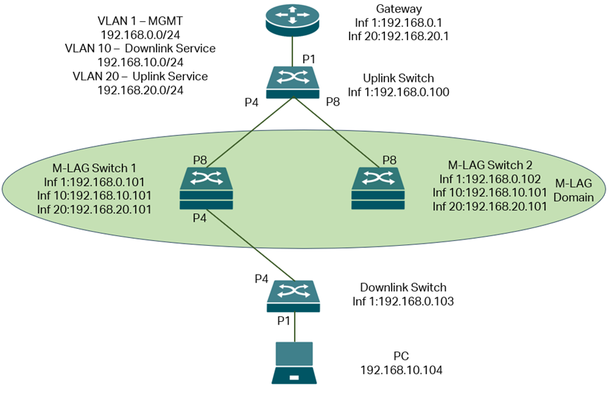
The topology for this scenario goes like this:
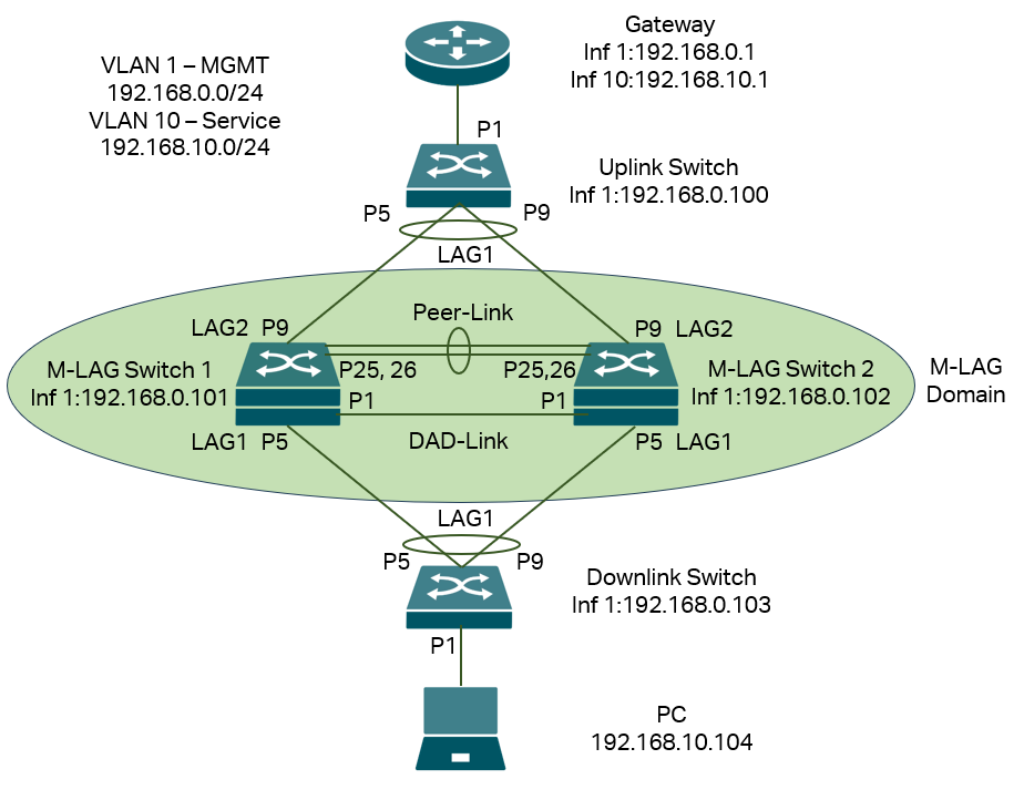
In this scenario, we have VLAN 1 for management, so every device have IP address on interface VLAN 1 for management, but for service VLAN running traffic which is VLAN 10, only the PC and router have interface with IP addresses in this VLAN, all the switches in between, including the M-LAG system don’t need interface in VLAN 10 as they are only handling layer 2 forwarding. All the IP addresses in this example will be configured statically, please note that it is recommended to configure a static IP address for the M-LAG peer devices as the DHCP packets may go to another peer device, causing a problem in DHCP interaction for peer devices, for other devices not involving M-LAG, DHCP is also good to use.
Briefly, what we need to do is power up the devices, configure the VLAN, interfaces and IP addresses, enable M-LAG on peer devices, configure peer-link, DAD-link, member ports as well as the LAGs between M-LAG peer devices and other devices, configure VLAN status on all ports and LAGs.
Step 1. Power up all devices but don’t connect the DAD-Link and Peer-Link on the topology. For the LAGs, do not connect all the cables, because the LAGs, Peer-Link and DAD-Link are not configured, connecting all the cables may cause conflict and chaos in the topology. For the LAGs, connect the devices to different ports first, ensure the LAG ports shown in the topology is vacant, otherwise the connection may be dropped during the LAG configuration later. After connecting, adopt the devices to the Omada Pro Network System.
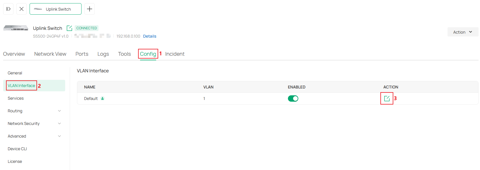
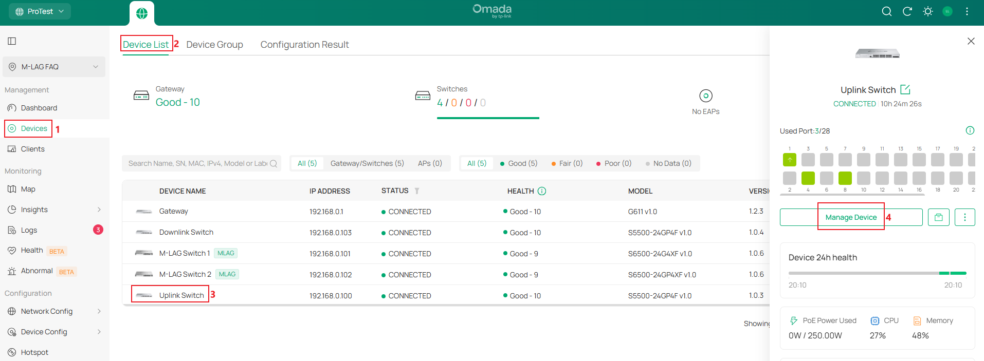
Step 2. Configure the IP address of interface VLAN 1 statically on all switches, this could ensure the management IP address are stable when creating M-LAG and during its operation. Go to Devices -> Device List, click on a switch, in the pop out page, click Manage Device.

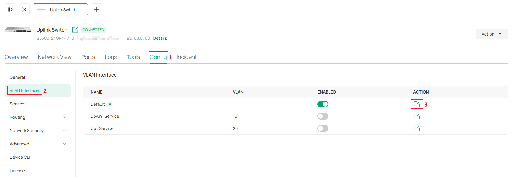
Then go to Config -> VLAN Interface, click the Edit button on VLAN 1.
In the configuration page, set IP Address Mode as Static, enter the IP Address, Subnet Mask, Default Gateway and Primary DNS accordingly, click Save to finish the configuration.
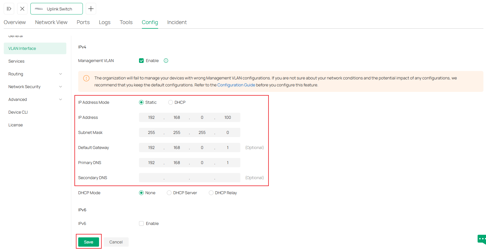
Conduct the process for all switches adopted, the final result should be all switches in this site are using static IP address for the interface of management VLAN, which is also the default VLAN in this example.
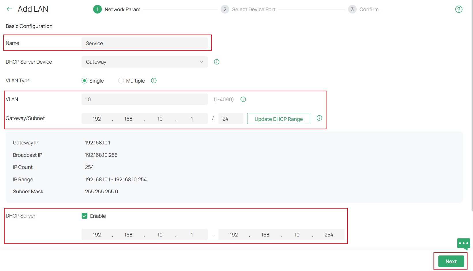
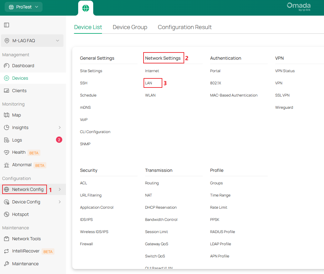
Step 3. Create VLAN 10 for the service network in the site. Go to Network Config -> Network Settings -> LAN.

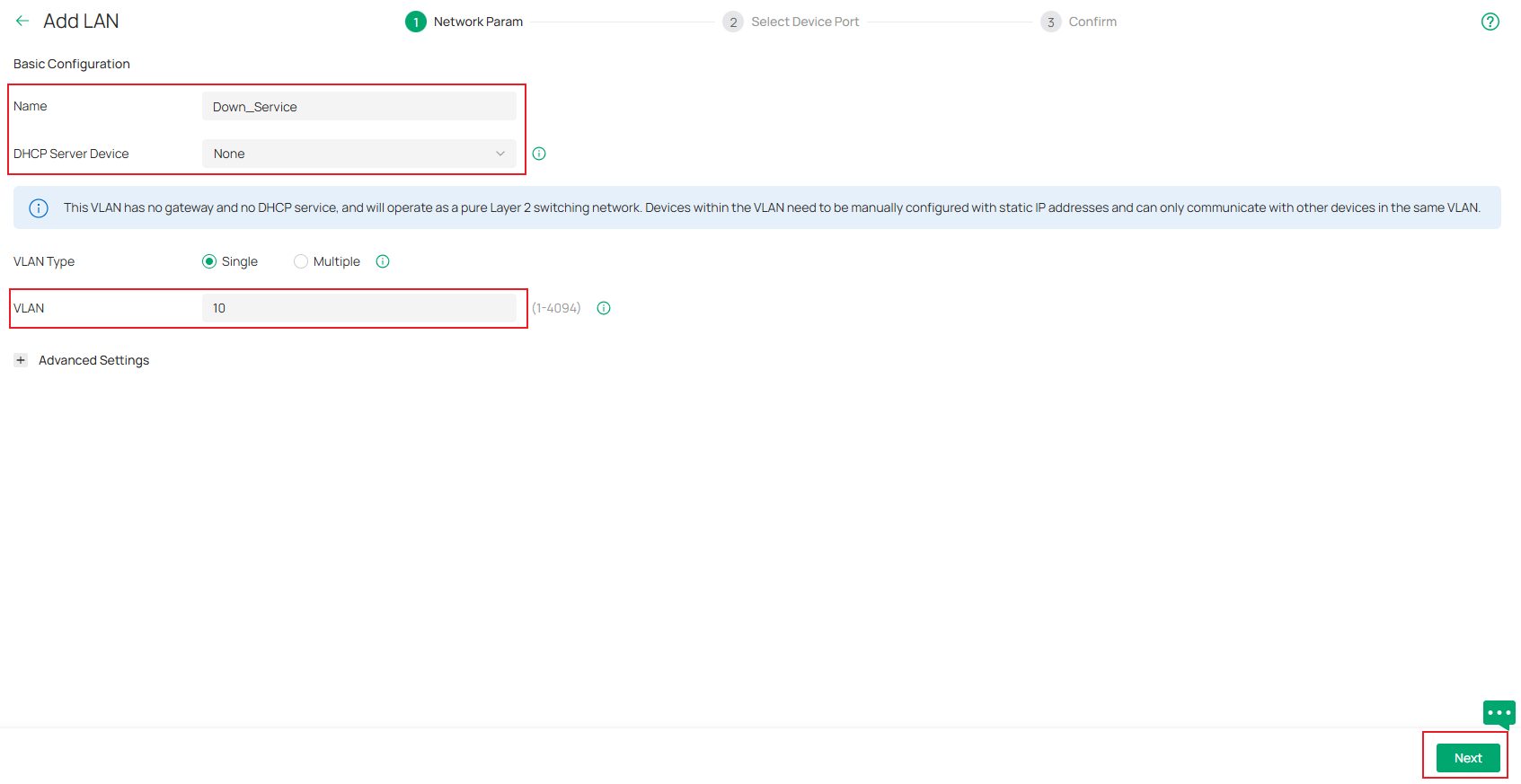
Click the Add button, in the configuration page, set the Name, VLAN ID, Gateway/Subnet and DHCP Server according to the example topology shown, click Next to enter the next step.
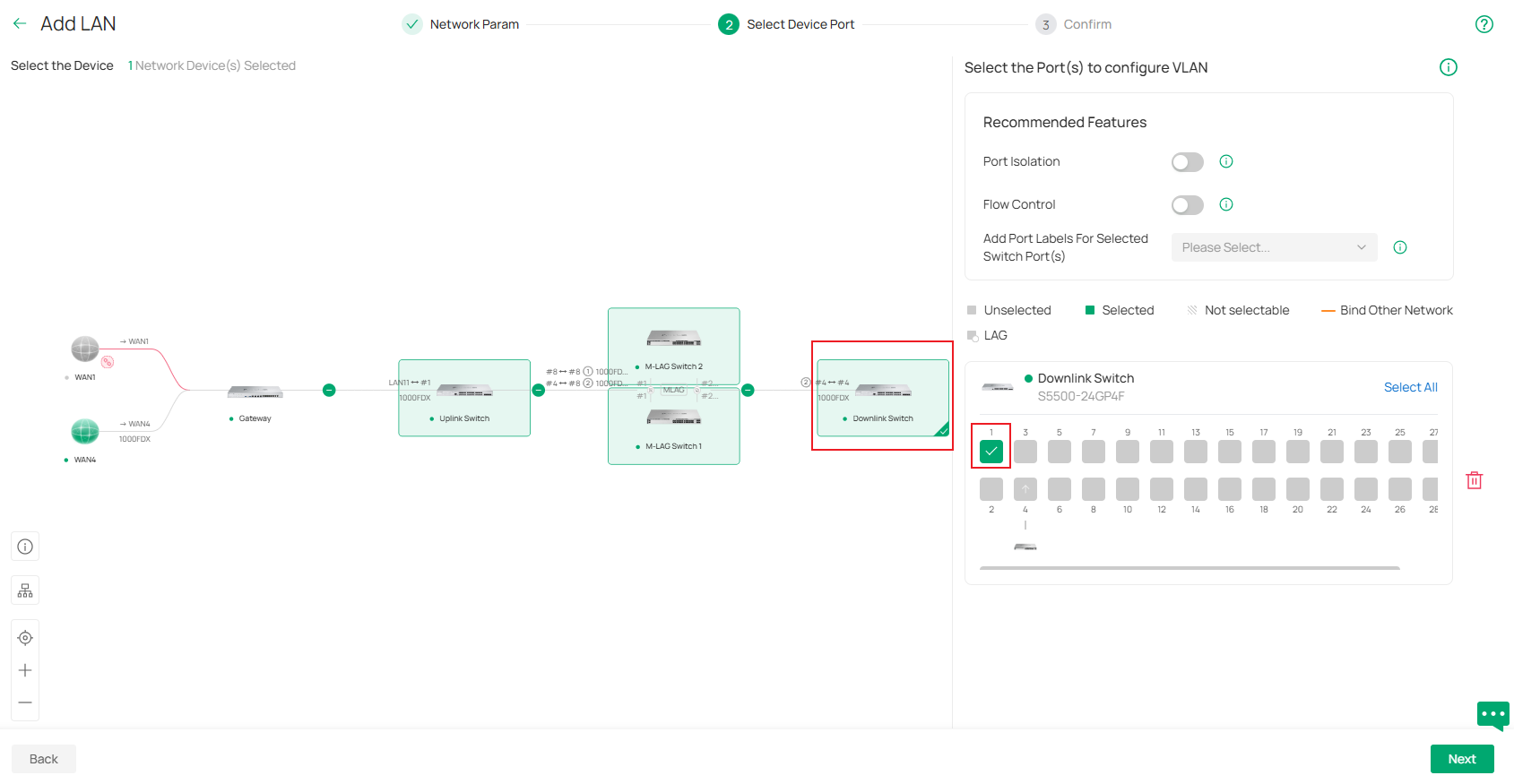
In the step of Select Device Port, choose the device and select the ports which will be connecting to end devices like PCs, this will make them become access ports of VLAN 10. In this example, it’s port 1 of the Downlink Switch. Click Next to proceed.
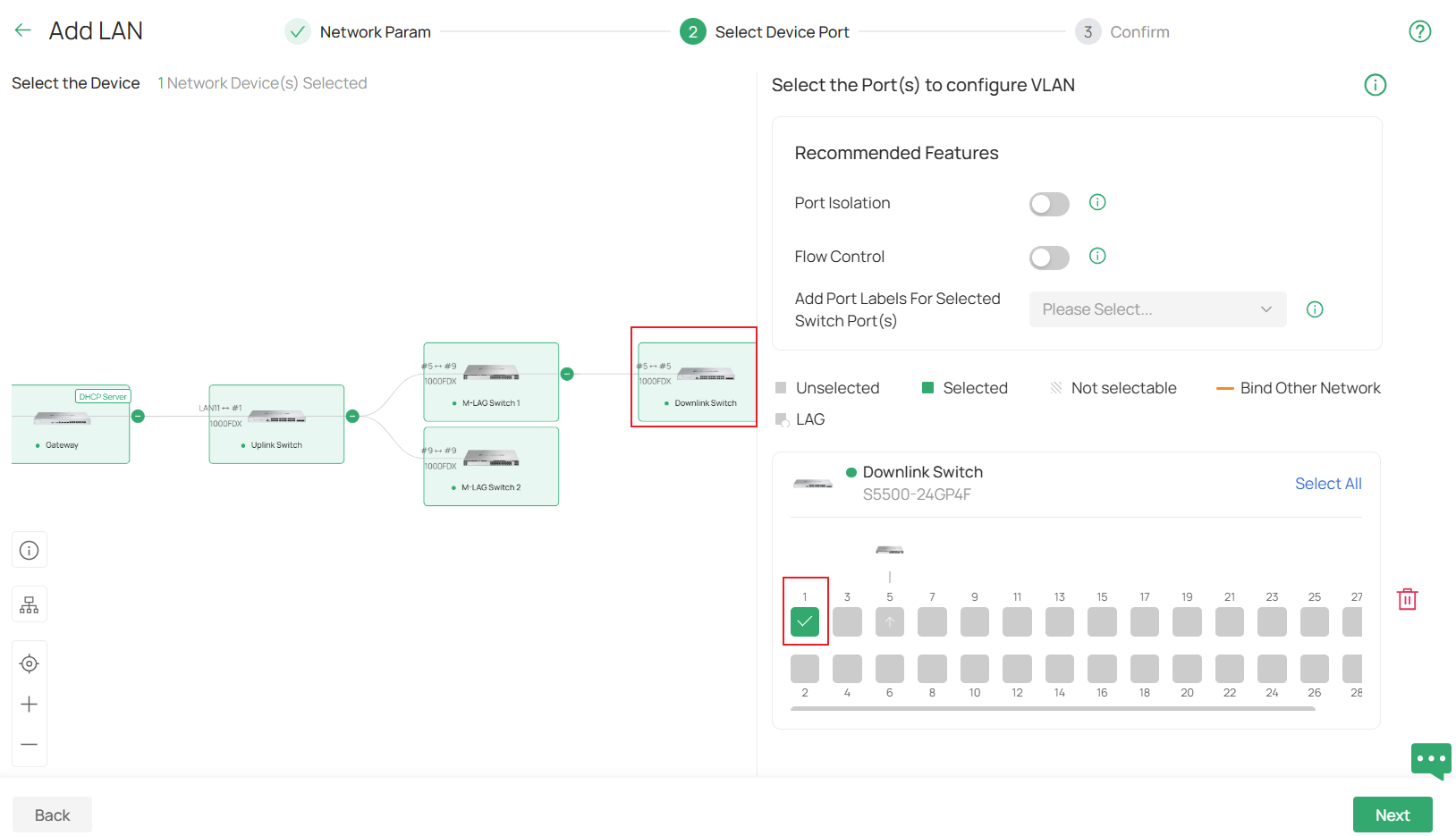
Finally, in the Confirm page, double check if all the parameters are set correctly, click Apply to finish creating the new LAN.
Step 4. Enable M-LAG on both peer switches, configure the peer-link and DAD-link. For the peer-link, only the uplink ports running at highest port speed could be used, which means the media used to act as the peer-link must match the highest speed of uplink ports, for example, if the uplink ports are 10G SFP+ ports, an 1G DAC could not be used to form the peer-link. You could also configure multiple links as peer-link by configuring multiple ports as peer-link ports. For the DAD-link, as we said before, it is a purely IP-based link and the ports on both sides will be acting as routed port, so we need to specify the peer and source IP address when configuring DAD-Link.
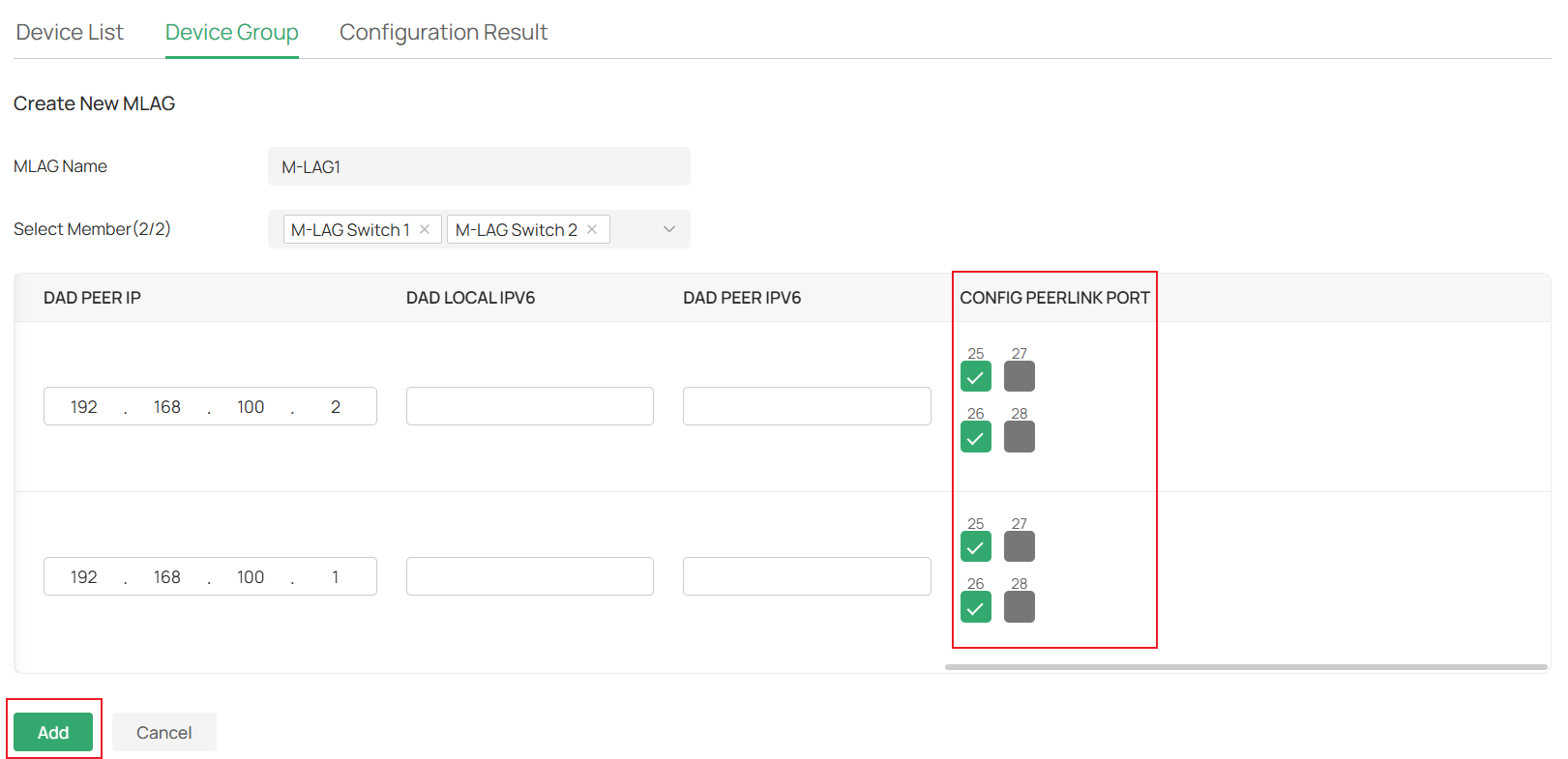
Go to Devices -> Device Group -> MLAG Group, click Create New MLAG.

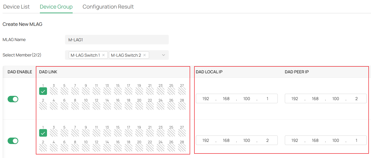
Set the MLAG Name, choose the two member switches which will be establishing the M-LAG connection, enter the Priority as you want, this will only affect which switch will take over all the traffic forwarding if the M-LAG connection encounters a problem.

Scroll right, select the DAD Link ports on both member switches, then set the corresponding DAD Local IP and DAD Peer IP. The DAD Local IP and DAD Peer IP should match each other while not conflicting with any existing subnets. We use 192.168.100.1 and 192.168.100.2 here.
Scroll right, choose the ports you want to use to connect peer link in the Config Peer Link section, in this example, we select port 25 and 26. Click Add after finishing the configuration.

We have now finished configuring peer-link and DAD-link. Please connect the peer-link and DAD-link cables according to the topology.
Step 5. Create all LAGs needed on switches. As M-LAG creates LAG across devices, we will configure LAG separately on both M-LAG peer switches. The ports within the LAG with the same LAG ID will be considered the same LAG across devices and will work together to connect to other devices. These LAGs will be configured as M-LAG member ports; the traffic entering from M-LAG member ports will be forwarded according to M-LAG rules.
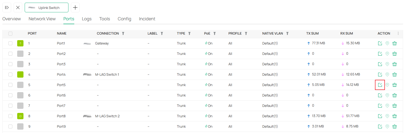
For example, on the Uplink Switch, add port 5 and 9 into LAG1 as passive LACP. Go to Devices -> Device List, click on the switch, in the pop-up page, click Manage Device.
In the switch configuration page, go to Ports, click the Edit button on one of the LAG member ports.

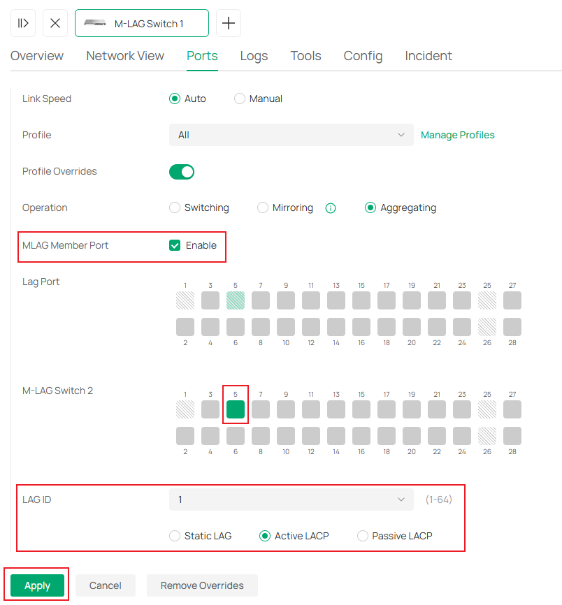
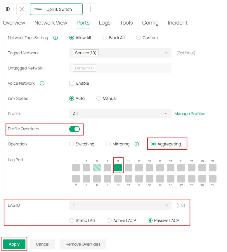
In the port configuration page, click to enable Profile Overrides, select Operation as Aggregating, select the other LAG member ports, set LAG ID as 1 and mode as Passive LACP. Click Apply to finish creating the LAG.

On M-LAG Switch 1, while configuring LAG, as the M-LAG connection is already established, you could select ports on both M-LAG member switches at the same time. Set port 5 on both sides as LAG 1, active LACP. Click Apply to save the configuration.
Repeat the step above to create LAGs on all the switches as described in the example topology. Port 5 and 9 as passive LACP on Downlink Switch, port 9 on both M-LAG member switches as active LACP.
Right now all the LAGs have been configured, all the cables could be connected according to the example topology.
Step 6. Now, all the LAGs have been created, change the cables between switches and make them connect to the LAG member ports as shown in example topology. Please note that the switches may disconnect while we change the cables, it should be back online after the topology is fully connected as shown.
Till here, we have finished the configuration for M-LAG system handling only layer 2 forwarding according to the example topology.
Configuration for M-LAG System Handling Layer 3 Forwarding
The topology for this scenario goes like this:
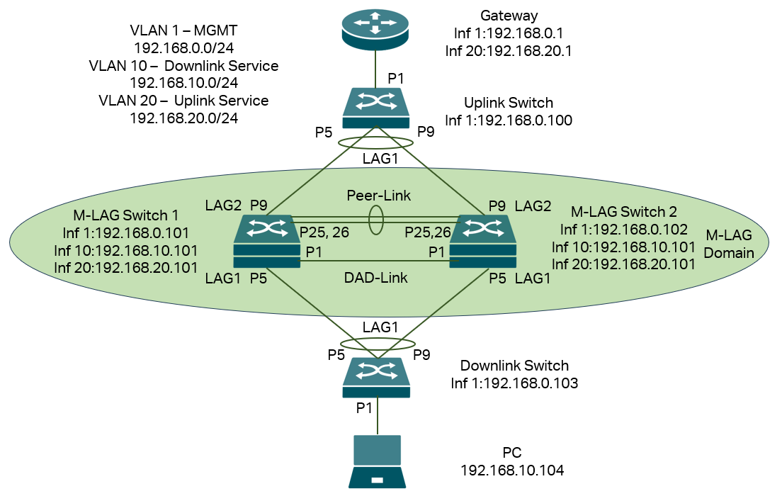
In this scenario, we have VLAN 1 for management, so every device have IP address on interface VLAN 1 for management, but for service VLAN running traffic, we separate them into two parts as the M-LAG system will handle layer 3 forwarding, for the downlink part of M-LAG system, use VLAN 10 as service VLAN, for the uplink part, use VLAN 20 as service VLAN.
For both M-LAG peer devices, they need to have interfaces in VLAN 1,10 and 20 for both management and layer 3 forwarding between uplink and downlink. For other switches, as they don’t need to handle layer 3 forwarding, only VLAN 1 interface for management is needed. All the IP addresses in this example will be configured statically, please note that it is recommended to configure static IP address for the M-LAG peer devices as the DHCP packets may go to the another peer device causing problem on DHCP interaction for peer devices, for other devices not involving M-LAG, DHCP is also good to use.
Briefly, what we need to do is connect the devices, configure the VLAN, interfaces and IP addresses, enable M-LAG on peer devices, configure peer-link, DAD-link, member ports as well as the LAGs between peer devices and other devices, configure VLAN status on all ports and LAGs.
Step 1. Power up all devices but don’t connect the DAD-Link and Peer-Link on the topology, for the LAGs, do not connect all the cables, because the LAGs, Peer-Link and DAD-Link are not configured, connecting all the cables may cause conflict and chaos in the topology. For the LAGs, connect the devices to different ports first, ensure the LAG ports shown in the topology is vacant, otherwise the connection may be dropped during the LAG configuration later. For example, we could connect the cable as this:
Step 2.Create VLAN 10 and 20 for the upstream and downstream service network in the site. For VLAN 10, it will be used for downstream service, so it will not be created on the gateway, go to Network Config -> Network Settings -> LAN.
Click the Add button, in the configuration page, set the Name, for DHCP Server Device, select None, or set as a switch as you need, then fill in the VLAN ID. Click Next to proceed, this will make VLAN 10 absent on the gateway.
In the step of Select Device Port, choose the device and select the ports that will be connecting to end devices like PCs, which will make them become access ports of VLAN 10. In this example, it’s port 1 of the Downlink Switch. Click Next to proceed.
Finally, in the Confirm page, double-check if all the parameters are set correctly, and click Apply to finish creating the new LAN.
For VLAN 20, it’s used for upstream service, so select the DHCP Server Device as the gateway, configure the DHCP server range for other steps, same as VLAN 10.
Step 3. Configure the IP address of interface VLAN 1 statically on all switches, this could ensure the management IP address are stable when creating M-LAG and during its operation. Go to Devices -> Device List, click on a switch, in the pop out page, click Manage Device.

Then go to Config -> VLAN Interface, click the Edit button on VLAN 1.
In the configuration page, set IP Address Mode as Static, enter the IP Address, Subnet Mask, Default Gateway and Primary DNS accordingly, click Save to finish the configuration.

While configuring on M-LAG member switches, apart from setting IP address for interface VLAN 1, also tick to enable interface for VLAN 10 and 20.
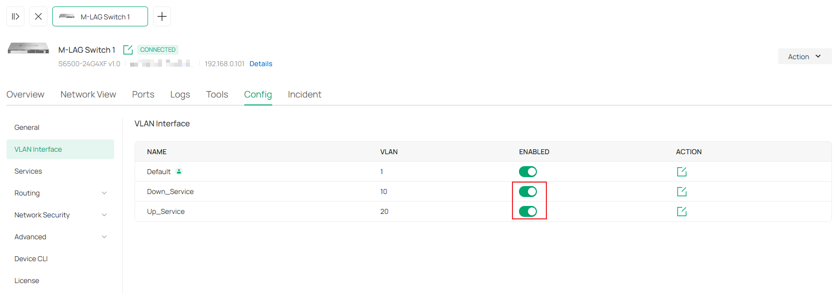
After that, configure static IP address for these two interfaces as well, the procedure is same as what’s shown above. As the two M-LAG member switches will act together while performing Layer 3 forwarding, the IP address of VLAN 10 and 20 interfaces on both sides need to be the same.
Conduct the process for all switches adopted, the result should be all switches in this site are using static IP address for the interface of management VLAN, which is also the default VLAN in this example.
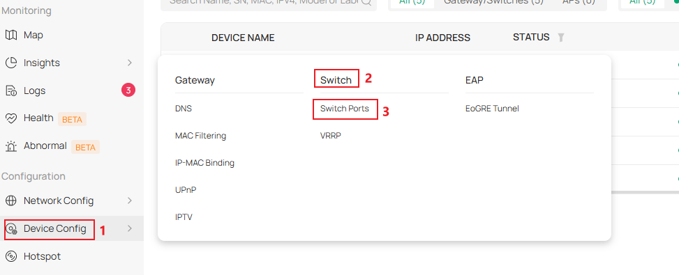
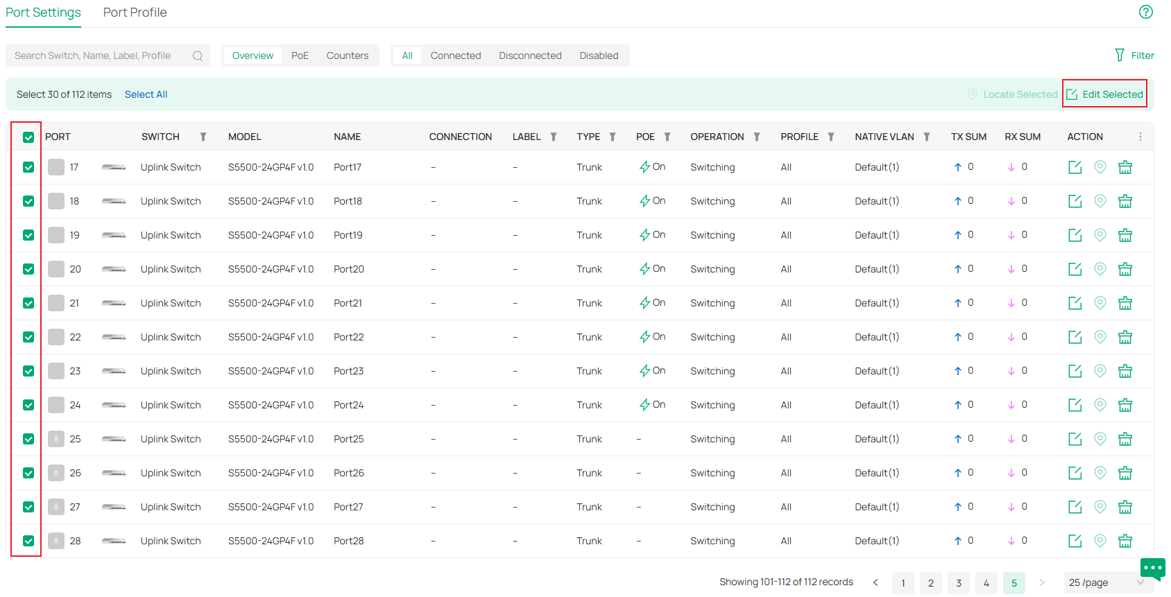
Step 4. Configure the VLAN status on all switches, as we are using VLAN 10 for downstream service, VLAN 20 for upstream service, we need to remove VLAN 10 from all ports of the Uplink Switch and the LAG member ports on M-LAG member switches connecting to the Uplink Switch. Go to Device Config -> Switch -> Switch Ports.
Batch select all the ports on Uplink Switch and also the LAG member ports on M-LAG member switches connecting to the Uplink Switch, click Edit Selected.
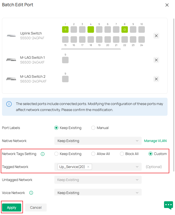
Change Network Tags Setting to Custom, select VLAN 20 only in Tagged Network. Click Apply to save the config.
After that, configure accordingly for VLAN 20, remove it from all ports in Downlink Switch and the LAG member ports on M-LAG member switches connecting to the Downlink Switch.
Step 5. Enable M-LAG on both peer switches, configure the peer-link and DAD-link. For the peer-link, only the uplink ports running at highest port speed could be used, which means the media used to act as the peer-link must match the highest speed of uplink ports, for example, if the uplink ports are 10G SFP+ ports, an 1G DAC could not be used to form the peer-link. You could also configure multiple links as peer-link by configuring multiple ports as peer-link ports. For the DAD-link, as we said before, it is a purely IP-based link and the ports on both sides will be acting as routed port, so we need to specify the peer and source IP address when configuring DAD-Link.
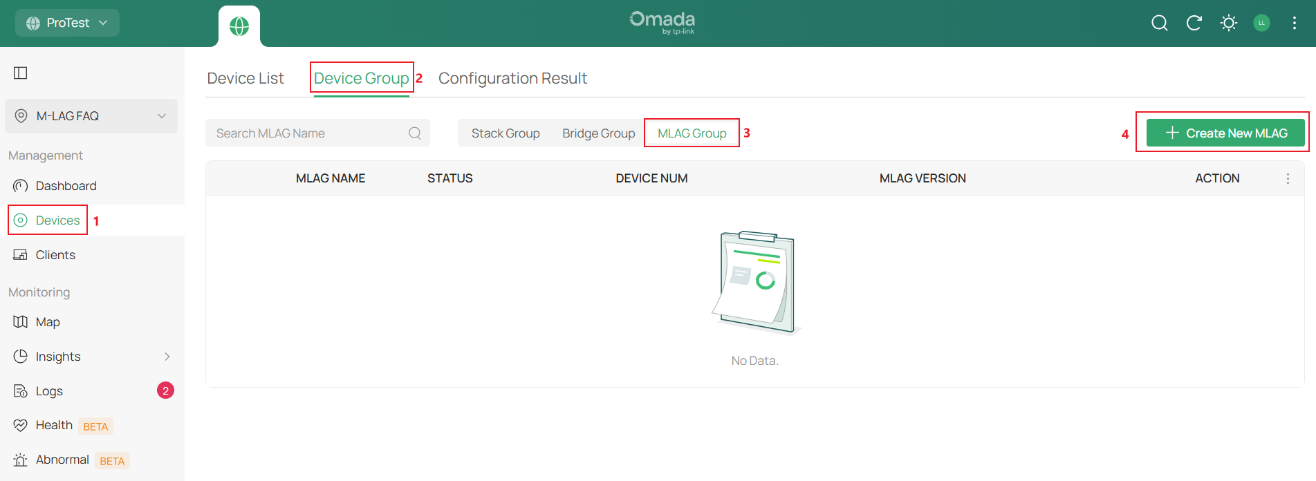
Go to Devices -> Device Group -> MLAG Group, click Create New MLAG.
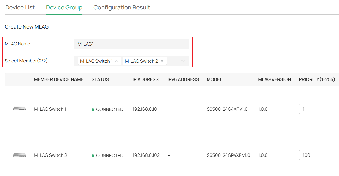
Set the MLAG Name, choose the two member switches that will establish the M-LAG connection, and enter the Priority as you want; this will only affect which switch will take over all the traffic forwarding if the M-LAG connection encounters a problem.
Scroll right, select the DAD Link ports on both member switches, then set the corresponding DAD Local IP and DAD Peer IP, the DAD Local IP and DAD Peer IP should match each other while not conflicting with any existing subnets, here we use 192.168.100.1 and 192.168.100.2.

Scroll right, choose the ports you want to use to connect peer link in the Config Peer Link section, in this example, we select port 25 and 26. Click Add after finishing the configuration.
Right now, we have finished configuring peer-link and DAD-link, and connected the peer-link and DAD-link cables according to the topology.
Step 6. Create all LAGs needed on switches. As M-LAG creates LAG across devices, we will configure LAG separately on both M-LAG peer switches. The ports within the LAG with the same LAG ID will be counted as the same LAG across devices and work together to connect to other devices. These LAGs will be configured as M-LAG member ports. The traffic entering from M-LAG member ports will be forwarded according to M-LAG rules.
For example, on the Uplink Switch, add ports 5 and 9 to LAG1 as passive LACP. Go to Devices -> Device List, click on the switch, in the pop-up page, click Manage Device.

In the switch configuration page, go to Ports, click the Edit button on one of the LAG member ports.
In the port configuration page, click to enable Profile Overrides, select Operation as Aggregating, select the other LAG member ports, set LAG ID as 1 and mode as Passive LACP. Click Apply to finish creating the LAG.
On M-LAG Switch 1, while configuring LAG, as the M-LAG connection is already established, you could select ports on both M-LAG member switches at the same time. Set port 5 on both sides as LAG 1, active LACP. Click Apply to save the configuration.

Repeat the step above to create LAGs on all the switches as described in the example topology. Port 5 and 9 as passive LACP on Downlink Switch, port 9 on both M-LAG member switches as active LACP.
Step 7. Now, all the LAGs have been created, connect the peer-link, DAD-link, change the cables between switches and make them connect to the LAG member ports as shown in example topology. Please note that the switches may disconnect while we change the cables, it should be back online after the topology is fully connected as shown.
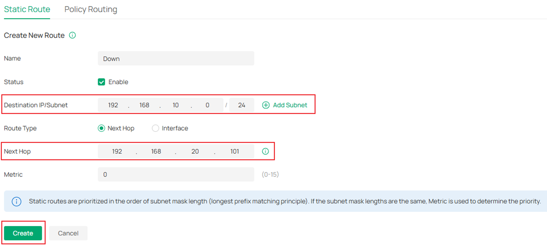
Step 8. To make sure the traffic could go back from the uplink to downlink, a static route may need to be created on the gateway.
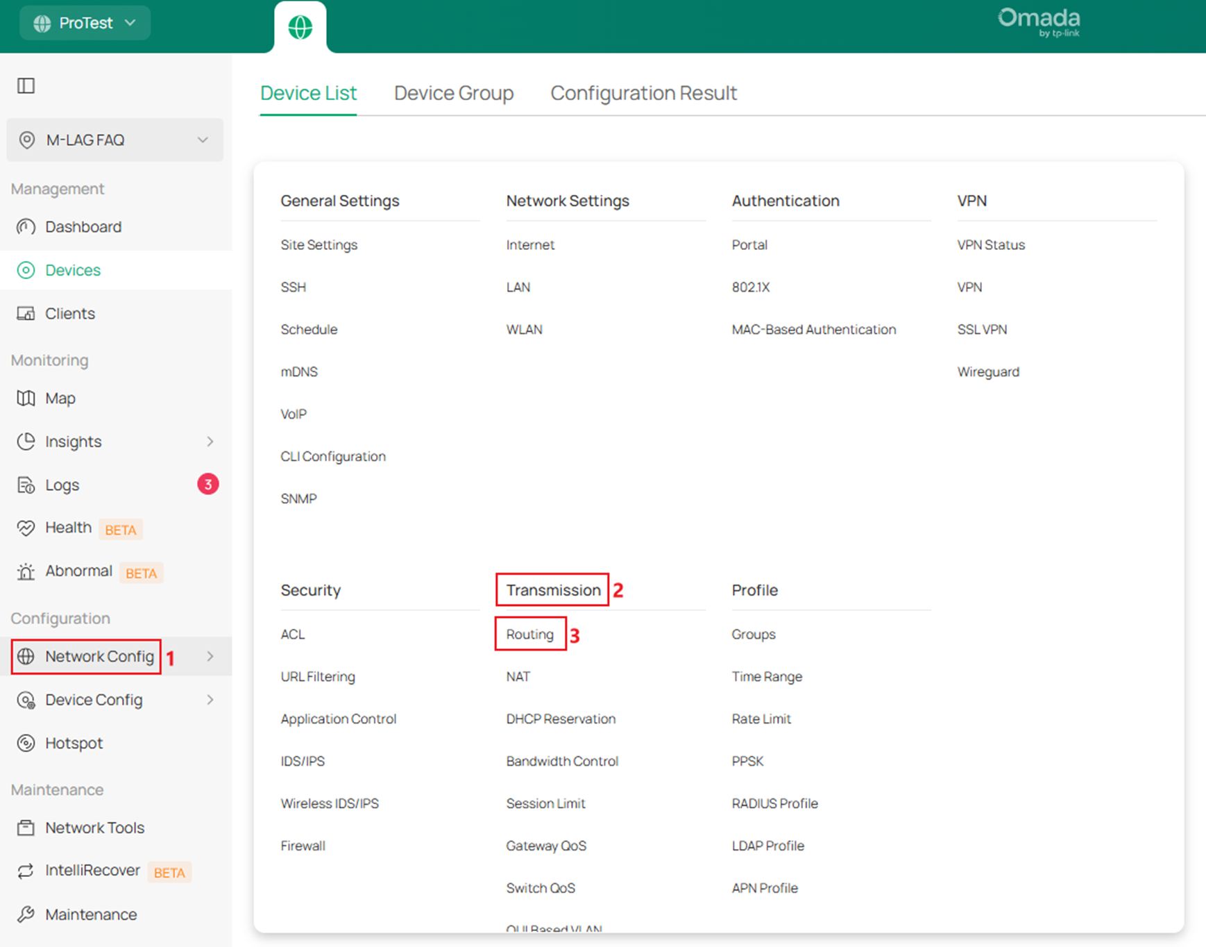
For this example, we need to create a static route towards 192.168.10.0/24, next hop is 192.168.20.101. Go to Network Config -> Transmission -> Routing.
In Static Route page, click Create New Route.
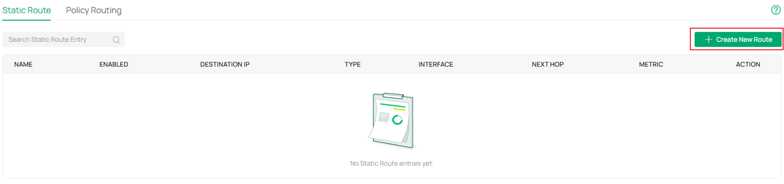
Enter the Name, Destination IP/Subnet, Next Hop, click Create.
Till here, we have finished the configuration for M-LAG system handling layer 3 forwarding according to the example topology.
Verification
After finishing the configuration, we could verify the link connection via ping from PC to the gateway:
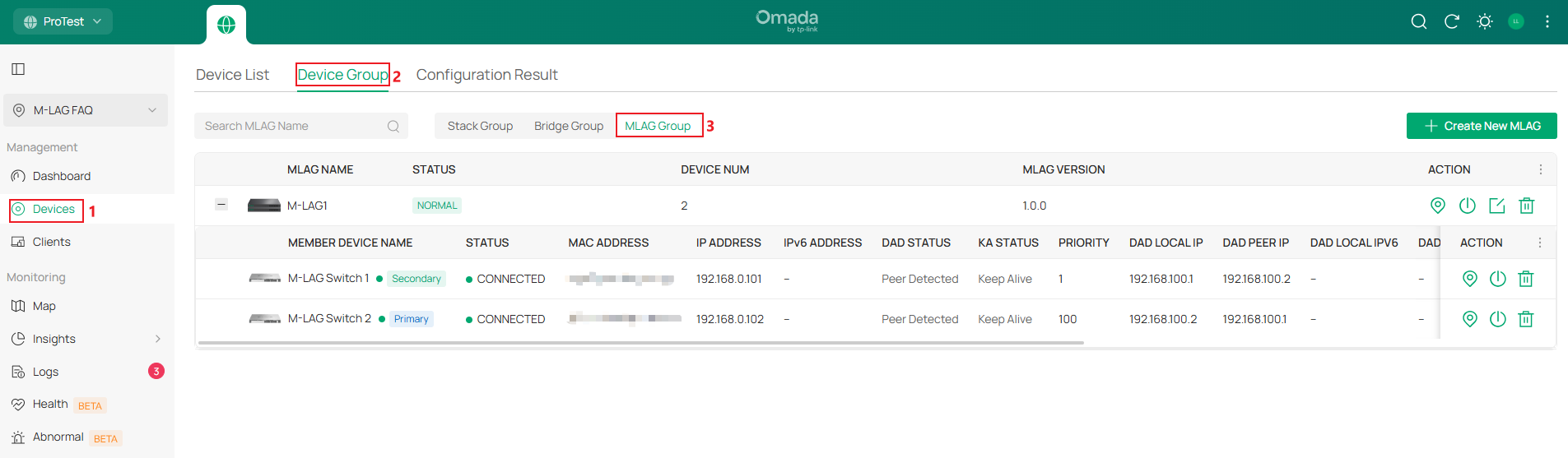
To verify if the M-LAG is working normally, go to Devices -> Device Group -> MLAG Group, the current MLAG status will be shown here, including if the members are online, if the DAD link is working.
Make a long ping from PC to the gateway, during the ping, perform the following actions one at a time to emulate device or link failure in operation and the ping should not be interrupted or only 1-2 packet loss, showing the both the resiliency and redundancy brought by M-LAG, which is better than stacking:
- Unplug one cable within a LAG
- Unplug the peer-link
- Unplug the DAD-link
- Shutdown one of the M-LAG peer devices
- Upgrade one of the M-LAG peer devices
Conclusion
Here we have made an introduction about what M-LAG is and give a simple example of M-LAG configuration on Omada Pro L3 switches in two scenarios.
Get to know more details of each function and configuration please go to Download Center to download the manual of your product.
