


How to Set Up Alarm Devices with Omada NVR


Contents
Configure Alarm Input Settings
Configure Alarm Output Settings
Configure Event-Triggered Alarm Linkage
Introduction
Omada NVR models equipped with Alarm In/Out interfaces support integration with external alarm devices, enabling automated monitoring and response actions. Alarm input devices, such as motion sensors, infrared detectors, smoke detectors, and door contacts, can trigger events on the NVR when abnormal conditions are detected. Alarm output devices, such as sirens, buzzers, and warning lights, can be activated automatically in response to configured events.
This article explains how to connect and configure alarm input and alarm output devices on Omada NVR, and how to create event-triggered alarm linkages.
Requirements
- Omada NVR with Alarm In/Out Interfaces
- External Alarm Devices (such as detectors, sensors, sirens, buzzers, or alarm lights)
Configuration
To complete the configuration, both the hardware installation and software configurations are required. Configuring alarm devices on Omada NVR involves the following steps:
- Connect alarm input devices.
- Connect alarm output devices.
- Configure alarm input settings.
- Configure alarm output settings.
- Configure event-triggered alarm linkage.
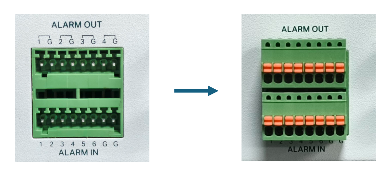
Before connecting external alarm devices, install the included terminal block into the corresponding alarm interface on the Omada NVR.
Connect Alarm Input Devices
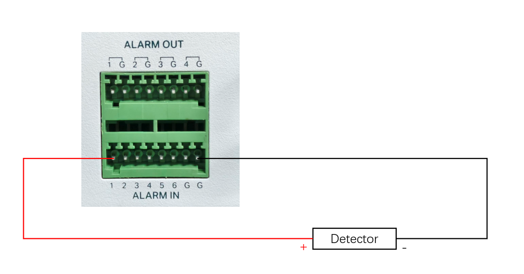
Step 1. Connect the positive terminal (COM, +) of the alarm input device to the corresponding ALARM IN (1-6) port on the NVR. Connect the negative terminal (NO/NC, -) to the corresponding ground terminal (G), as shown below.
Notes:
- The ground terminal of the alarm input (ALARM IN) requires the use of the G terminal shown in the above illustration and cannot be connected to the G terminal of the ALARM OUT connector.
- Normally Open (NO port) means that under normal conditions, the circuit is open and no current passes through the NVR, when the alarm is triggered, the current passes through the NVR and the NVR alarms.
- Normally Closed (NC port) means that normally the circuit is closed, and the NVR will alarm in case of a circuit fault or alarm trigger.
- The G terminals in Alarm In section are shared common ground terminals. When multiple detectors are installed, several devices can share the same G terminal.
Connect Alarm Output Devices
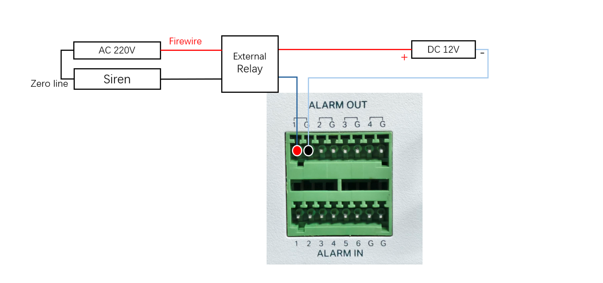
The alarm output can be connected to either DC or AC loads. When used as a control switch for AC circuits, it is imperative to use an external relay to avoid damage to the equipment and the risk of electric shock.
Connect a DC-powered alarm output device
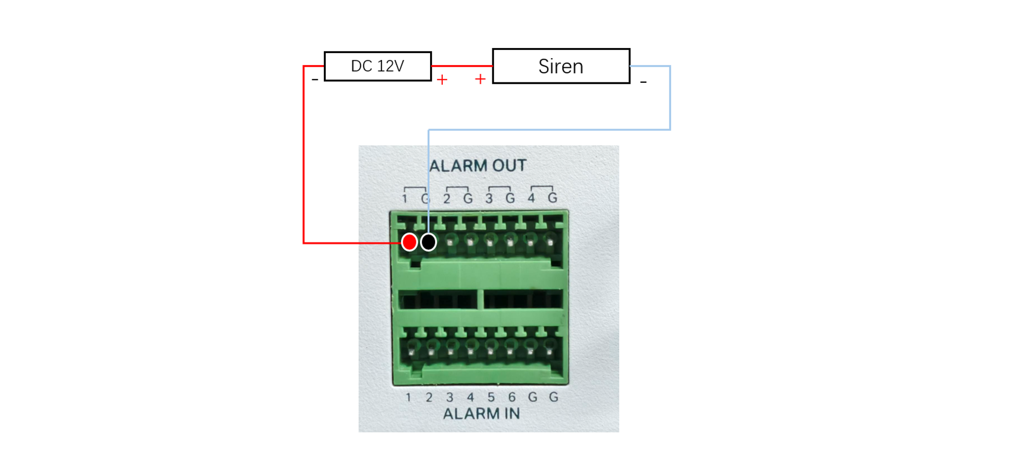
Step 1. Connect the positive terminal (+) of the alarm output device to the corresponding ALARM OUT (1-4) terminal on the NVR. Connect the negative terminal (-) to the matching ground terminal (G).
Notes:
- The alarm output port of the Omada NVR is compatible with DC loads of up to 24V.
- The NVR alarm output port (ALARM OUT) positive pole (marking 1~4) and the corresponding ground terminal (G) must be connected in a one-to-one manner and cannot be mixed.
Connect an AC-powered alarm output device
Step 1. Standard alarm outputs cannot directly drive high-voltage AC loads. When connecting an external AC-powered device, an external relay must be used to isolate and control the load safely, as shown in the diagram below.
After connecting the external alarm device to the Omada NVR, we need to configure alarm device on the Omada NVR GUI or Web interface. In this document, we will use the NVR Web interface to demonstrate how to configure the settings.
Configure Alarm Input Settings
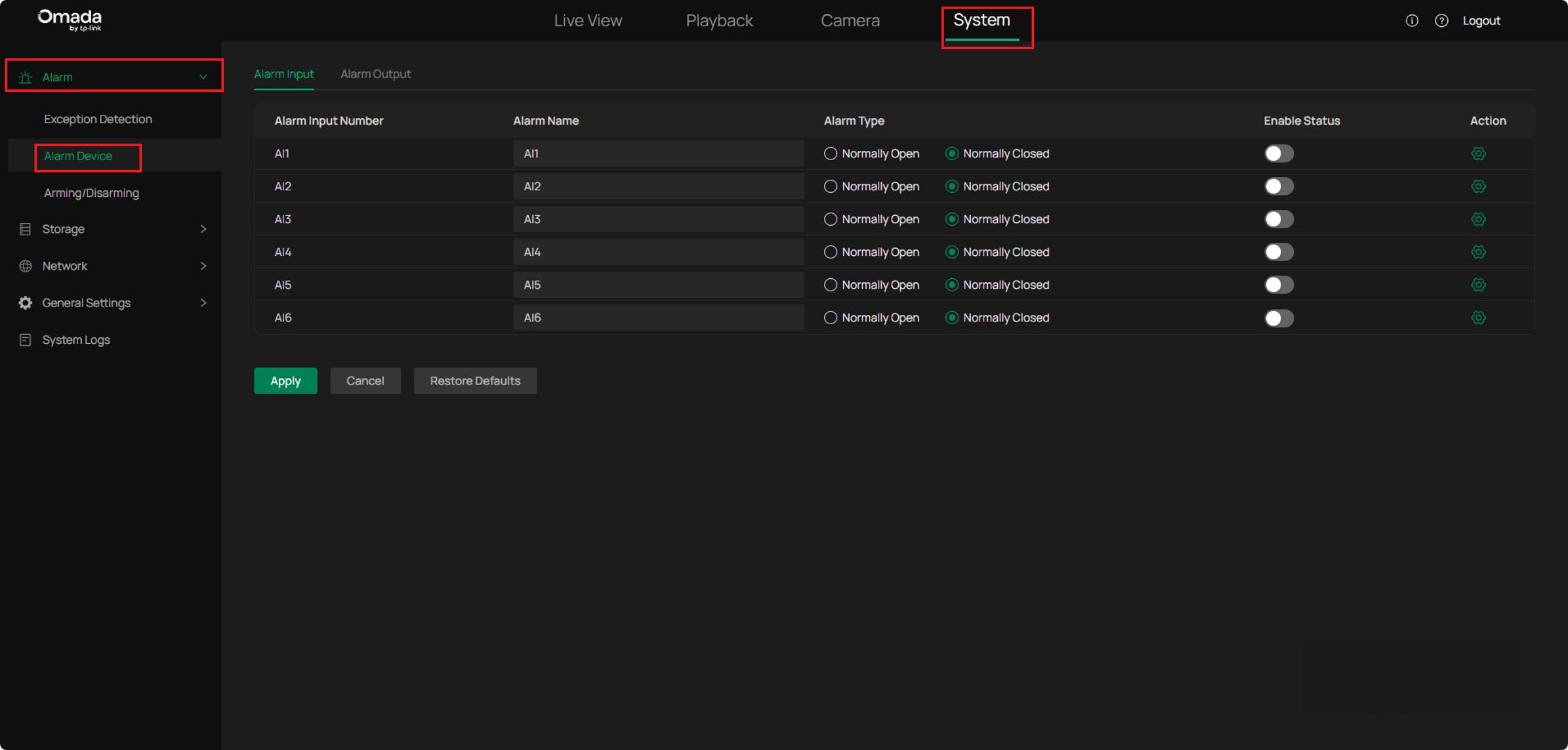
Step 1. Log in to the NVR Web interface. Navigate to System > Alarm > Alarm Device. Select an Alarm Input port from AI1 to AI6. The Alarm Name can also be customized for the selected port.
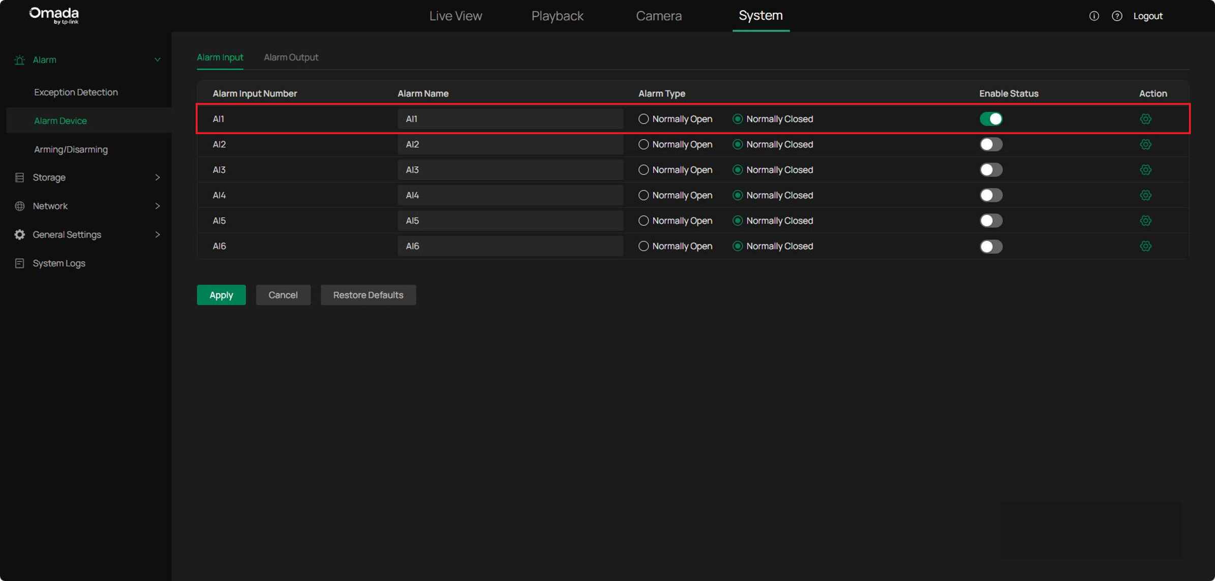
Step 2. During the hardware installation, the positive terminal of the alarm input device is connected to a specific ALARM IN port. In Alarm Input configuration page, you need to enable the corresponding port accordingly. Since the alarm input device is connected to port 1, enable AI1 accordingly.
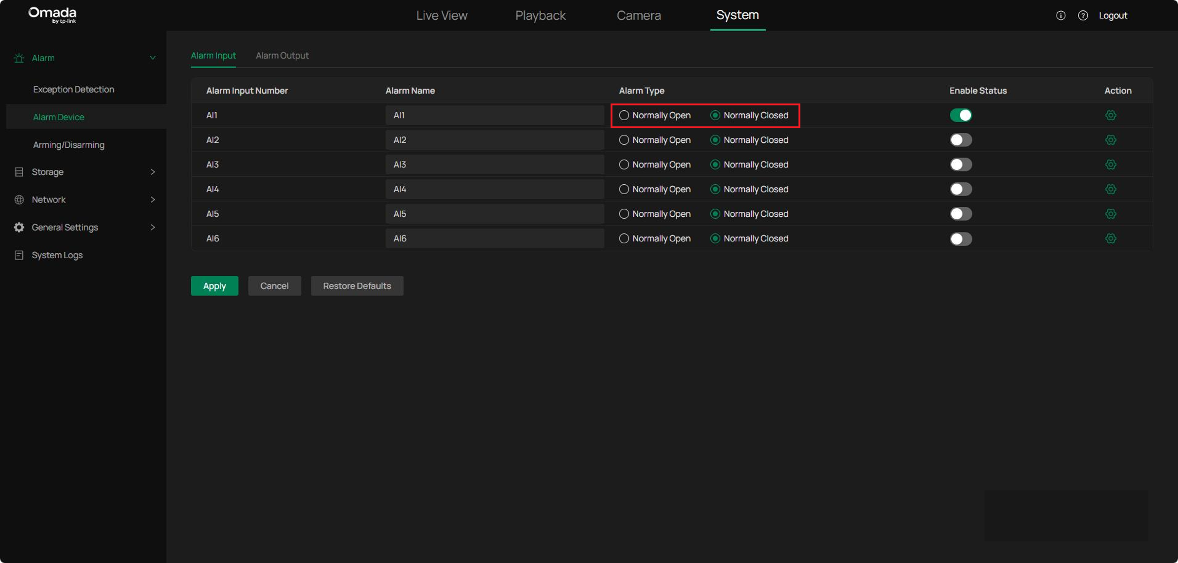
Step 3. Select the alarm type.
Two Alarm Types are available: NO (Normally Open) and NC (Normally Closed). Select the option that matches the connected alarm device.
Notes: Normally Open (NO) means that under normal conditions, the circuit is open and no current passes through the NVR, when the alarm is triggered, the current passes through the NVR and the NVR alarms.
Normally Closed (NC) means that normally the circuit is closed, and the NVR will alarm in case of a circuit fault or alarm trigger.
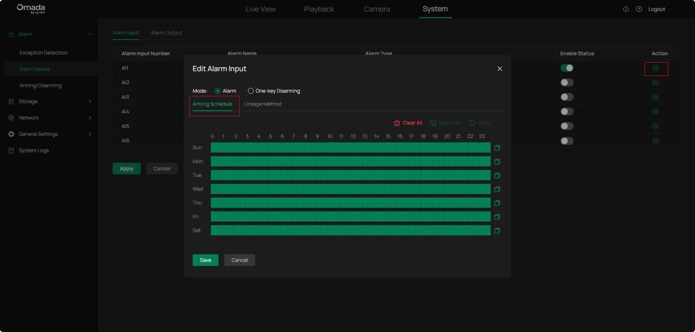
Step 4. Click AI1’s Action button. In Alarm Input Settings, set up Arming Schedule. After setting the Arming Schedule, click Confirm to save the configuration. The Alarm Input will only work during the set time interval.
Step 5. Configure Linkage Method. Four linkage methods are available. After selecting the desired method, click Confirm to save the settings.
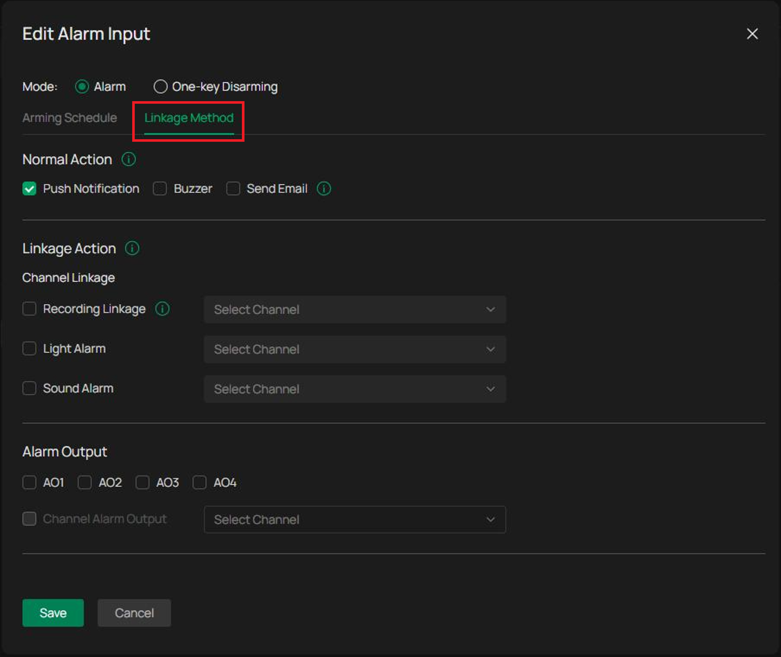
Normal Action: Available actions include:
- Push Notification
- Buzzer
- Send Email
When enabled, the selected actions are triggered when an alarm event occurs.

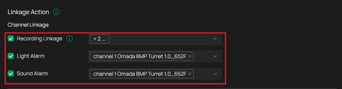
Linkage Action: Select one or more channels to be linked to the alarm input. When the Alarm Input is triggered, the selected channel(s) can automatically perform predefined actions, including Video Recording, Light Alarm, and Audible Alarm.
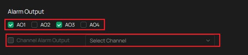
Alarm Output Linkage: Select one or more Alarm Output ports from AO1-AO4.
When the Alarm Input is triggered, the linked Alarm Output port sends an output signal to the connected alarm device.
If a connected IPC supports external alarm output interfaces, such as InSight S245ZI, the IPC can also be selected as an alarm output device.
Configure Alarm Output Settings
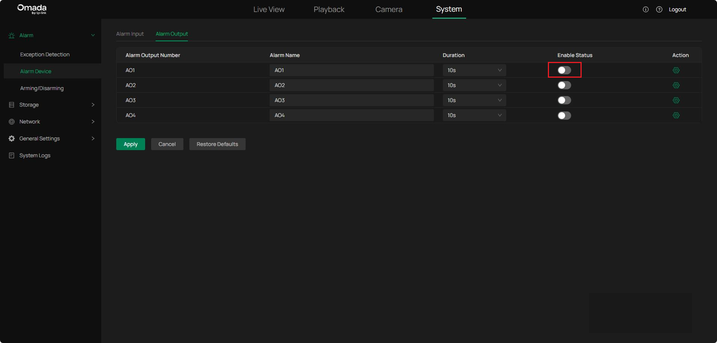
Step 1. Navigate to System > Alarm > Alarm Device > Alarm Output. Select Alarm Output port from AO1 to AO4. Click the Alarm Name field to modify the name of the port.
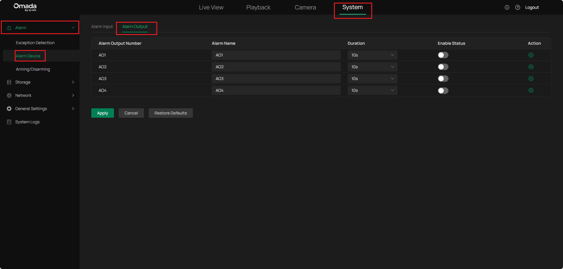
Step 2. During hardware installation, the alarm output device is connected to a specific ALARM OUT port. On the Alarm Output configuration page, enable the corresponding alarm output port based on the physical connection. For example, if the device is connected to ALARM OUT 1, enable AO1.
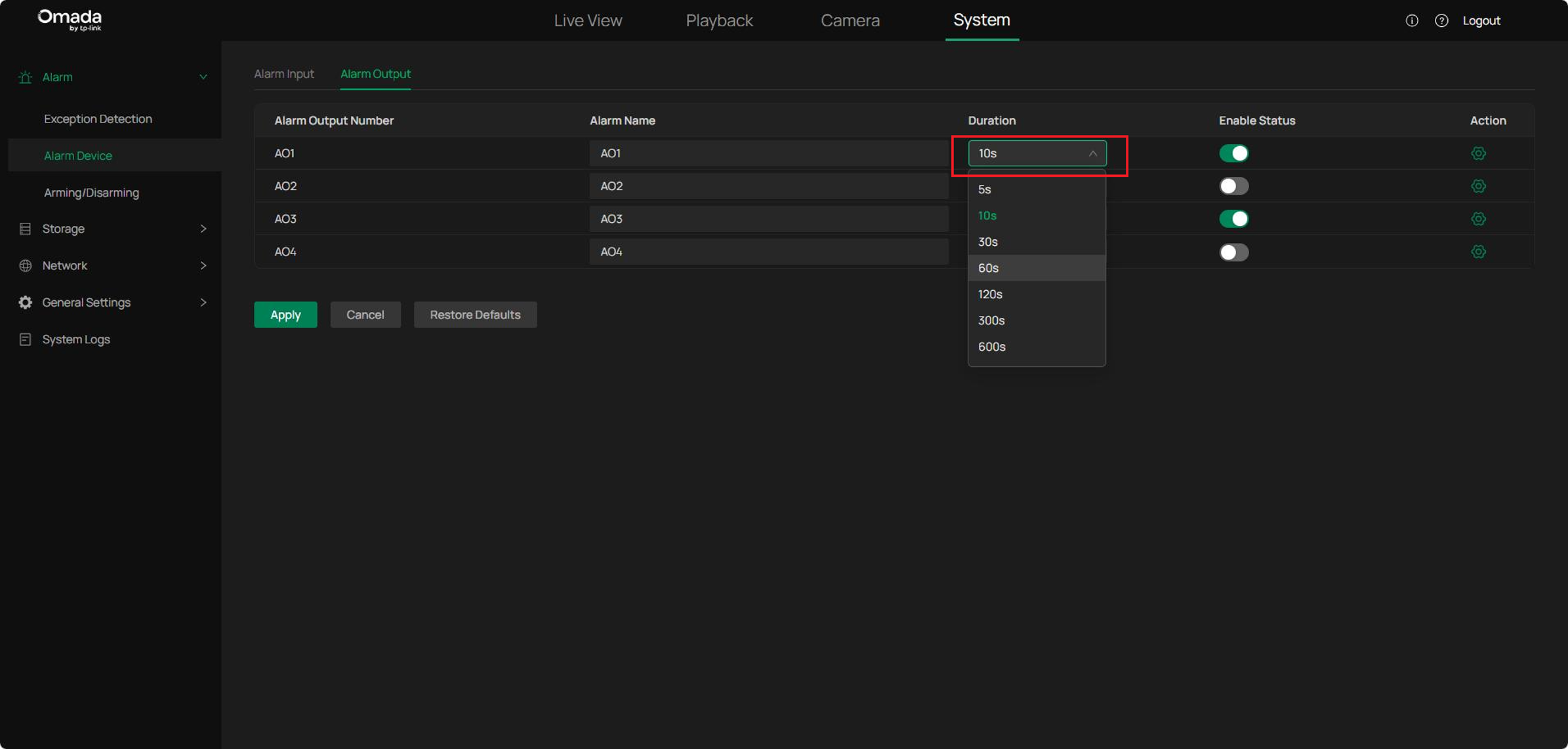
Step 3. Select the desired Duration for the alarm output, then click Apply.
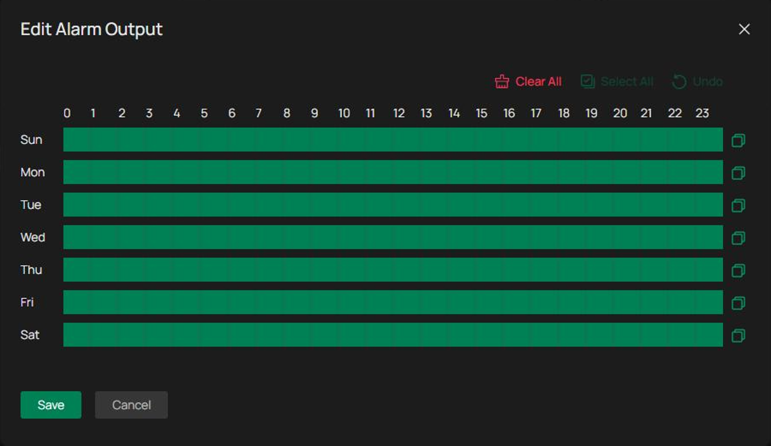
Step 4. Click Action to open Edit Alarm Output.
Configure the Arming Schedule and click Confirm.
The Alarm Output functions only during the configured schedule.
Configure Event-Triggered Alarm Linkage
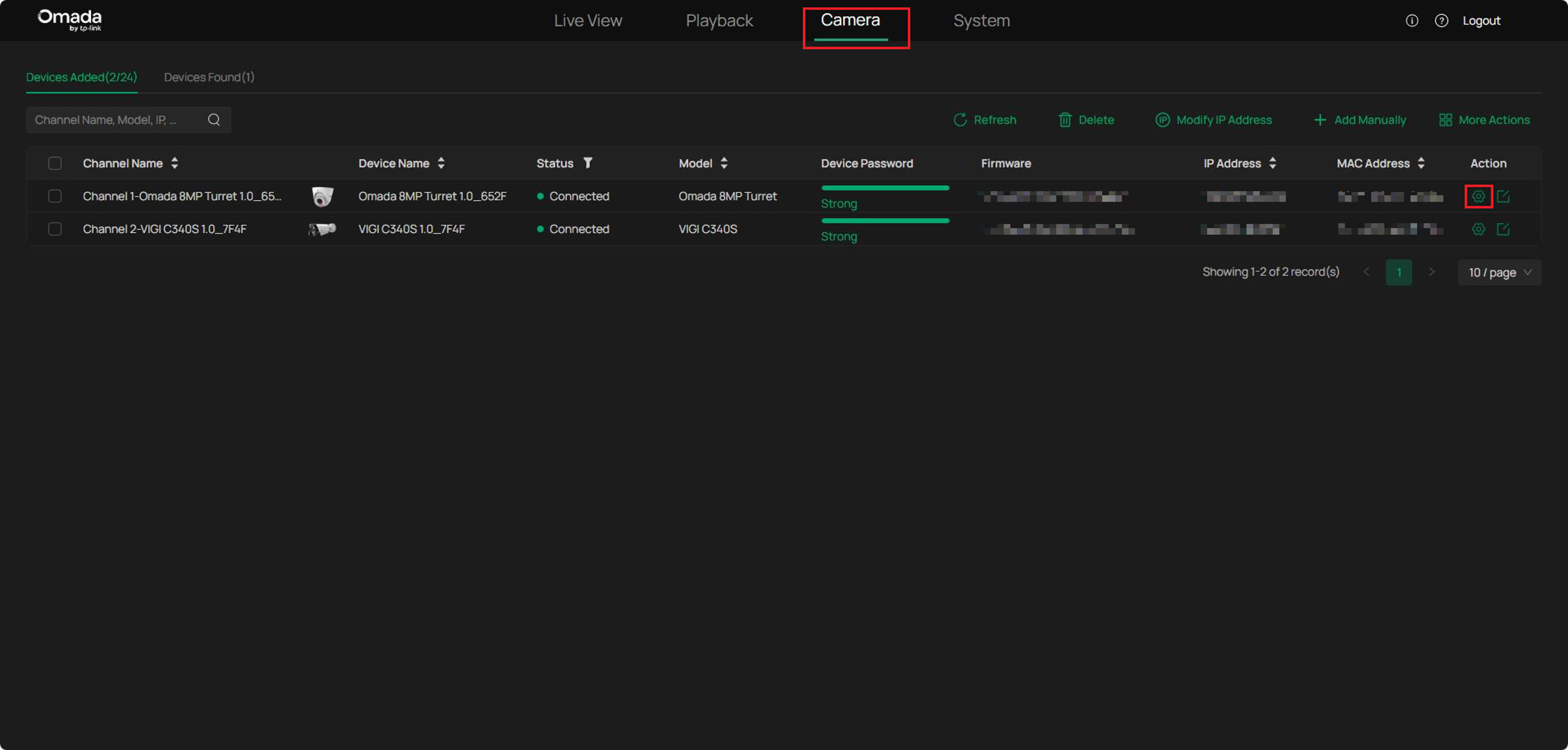
Step 1. Navigate to Camera, select a camera to configure Alarm Linkage, then click Action.
Step 2. Alarm linkage can be configured for different event types. This example uses Motion Detection.
Navigate to:
Event > Basic Event > Motion Detection > Triggered Action
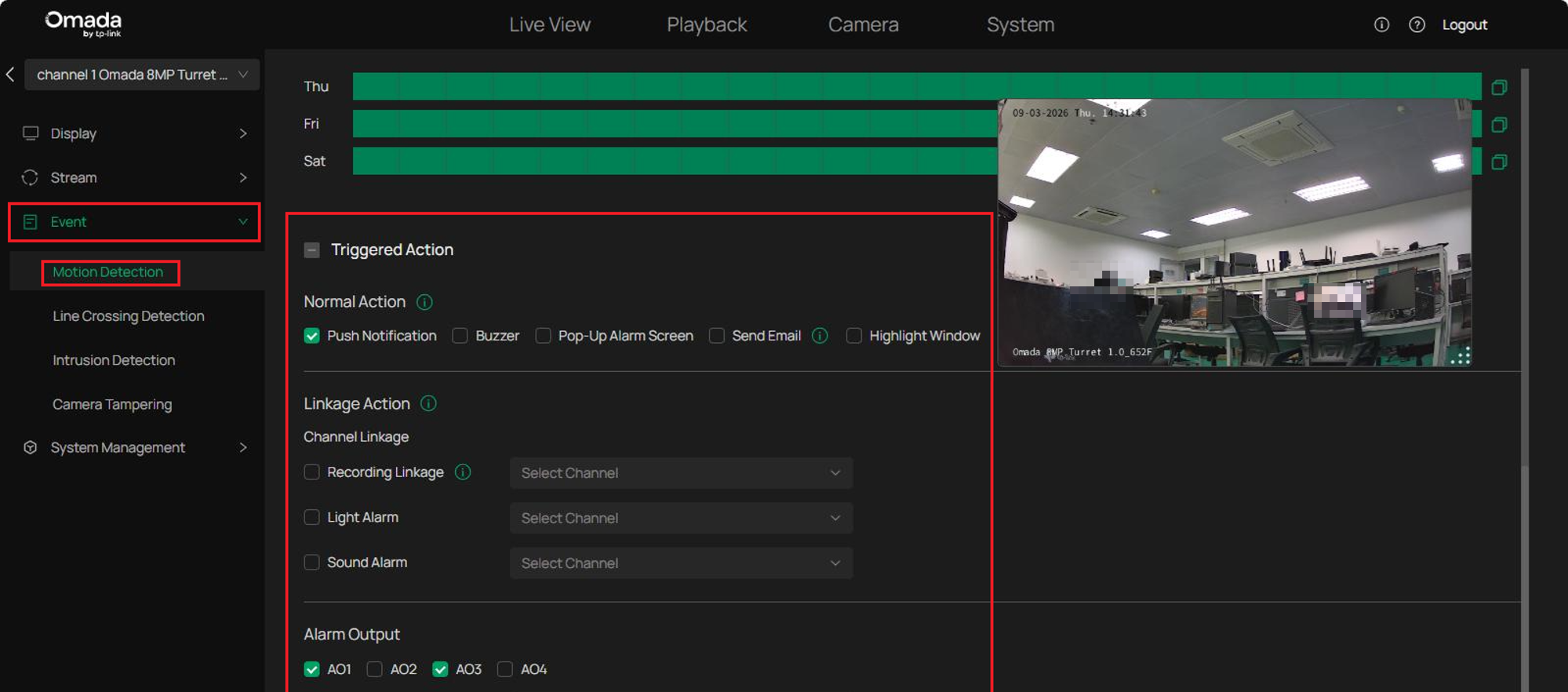
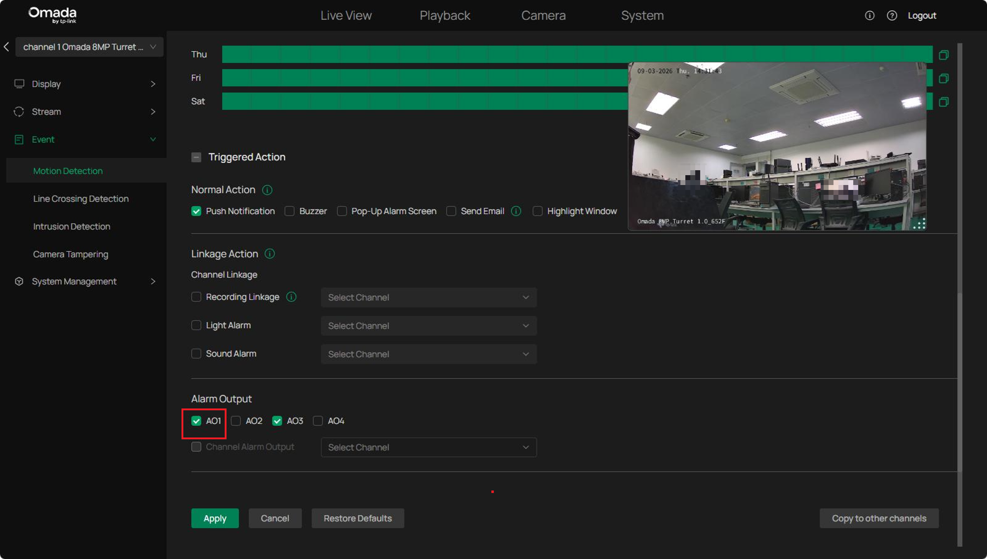
Step 3. Under Alarm Output Linkage, select AO1 and click Apply.
When a motion event is detected, the alarm output device connected to ALARM OUT 1 is activated automatically.
Conclusion
This article described how to connect and configure alarm input and alarm output devices on Omada NVR, including alarm schedules, linkage actions, and event-triggered alarm activation. Properly configured alarm devices can work with the NVR and connected cameras to provide automated alerts and response actions for enhanced security monitoring.
To learn more about each function and configuration, please visit Support Home to download or check the manual for your product.
