


How to use Omada Design Hub to identify DXF files


Contents
Introduction
In architectural design, AutoCAD software is frequently used. The DXF files exported by this software completely define the geometric content and logical structure of CAD drawings, specifically including geometric primitive data and the organizational structure that manages these primitives. Currently, Omada Design Hub supports the import of DXF files. You can import the DXF file of the site you wish to deploy the network into the platform and use a series of tools to better optimize the layout of network equipment.
Requirements
- DXF File
- Omada Design Hub
Configuration
The following section will provide a step-by-step explanation of the detailed process for importing DXF files.
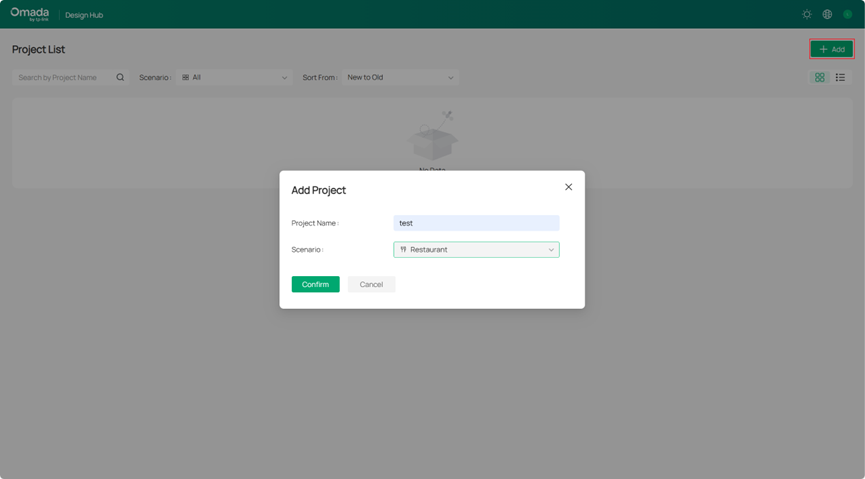
Step 1. Create a new Project
Edit the Project Name and Scenario after adding the project.
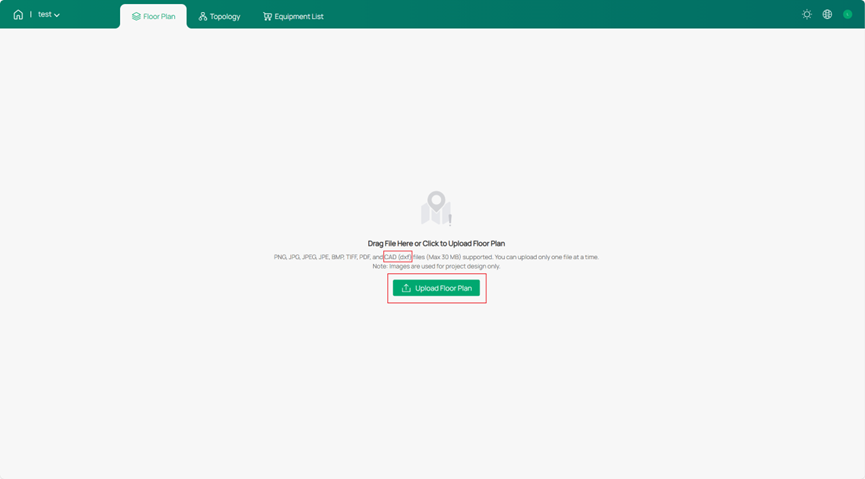
Step 2. Import a DXF file
Click Upload Floor Plan to import your DXF file. You can see the supported file types indicated in the notes.
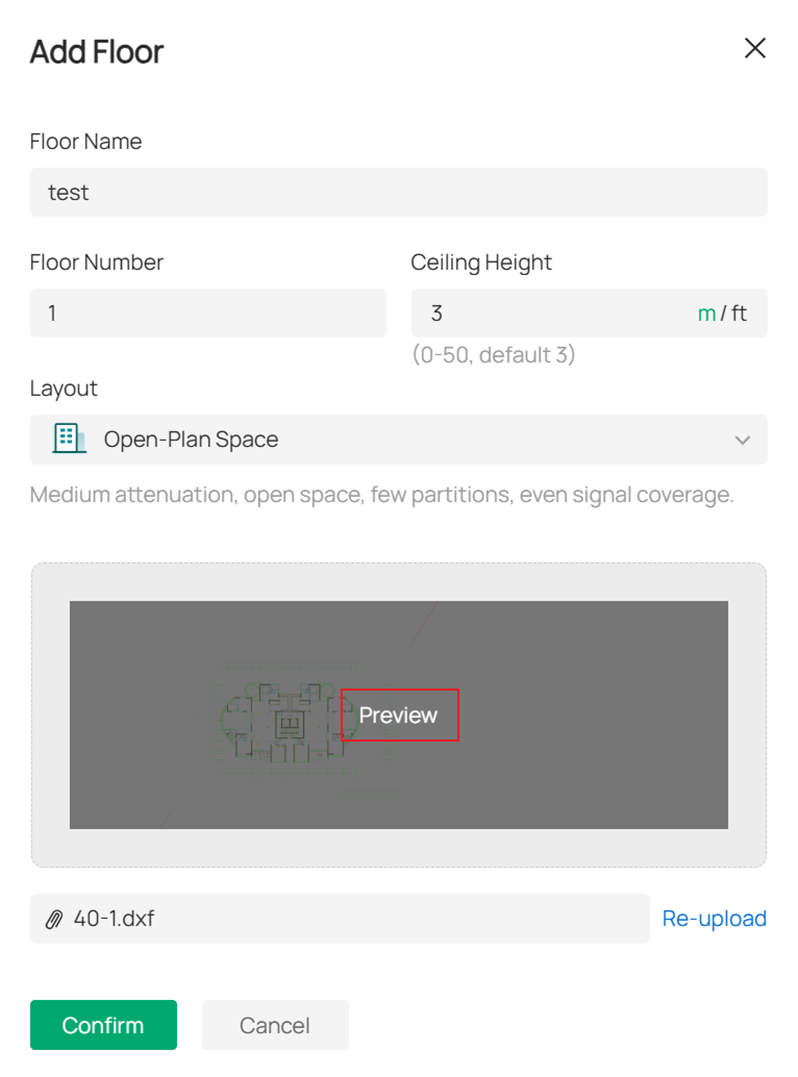
After the import is successful, you can customize the values of Floor Name, Floor Number, and Ceiling Height according to your needs, and you can Preview the layers by clicking on the image.
Step 3. Confirm the wall structure in the layers
After importing the DXF file, the Design Hub will automatically recognize the layer structure. At this step, you can choose which layers to designate as walls, as indicated in the page instructions. If you want to set a layer as a wall, click the checkmark icon on the right and select a wall type for it. Different wall types have varying effects on wireless signals. Click the eye icon to preview the current wall structure in the right-hand image (the open eye icon represents previewing, and the closed eye icon represents hiding).
Alternatively, you can directly click Cancel, which means no wall design will be applied at this stage, allowing you to manually design the walls later in the Floor Plan. However, note that the interface for selecting layers as walls is only editable immediately after the initial import. Once confirmed, the wall structure of the layers cannot be modified.
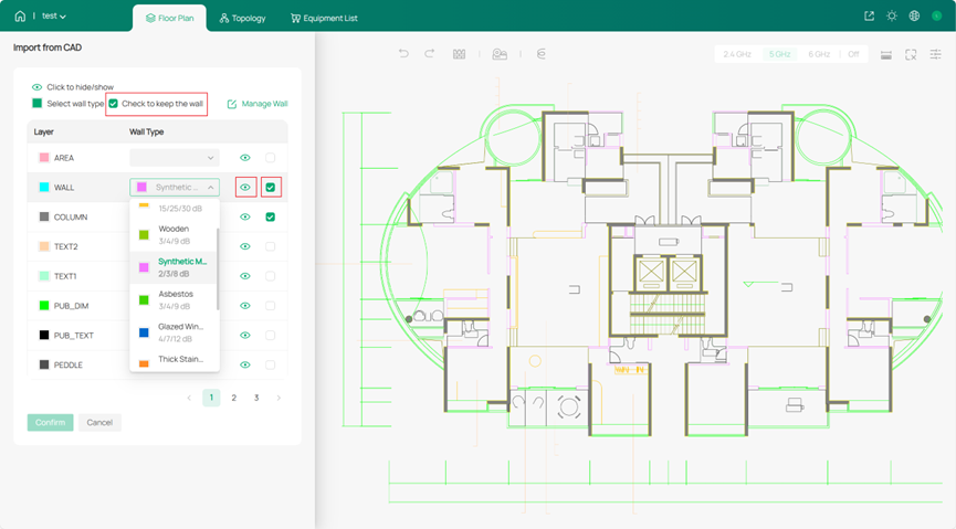
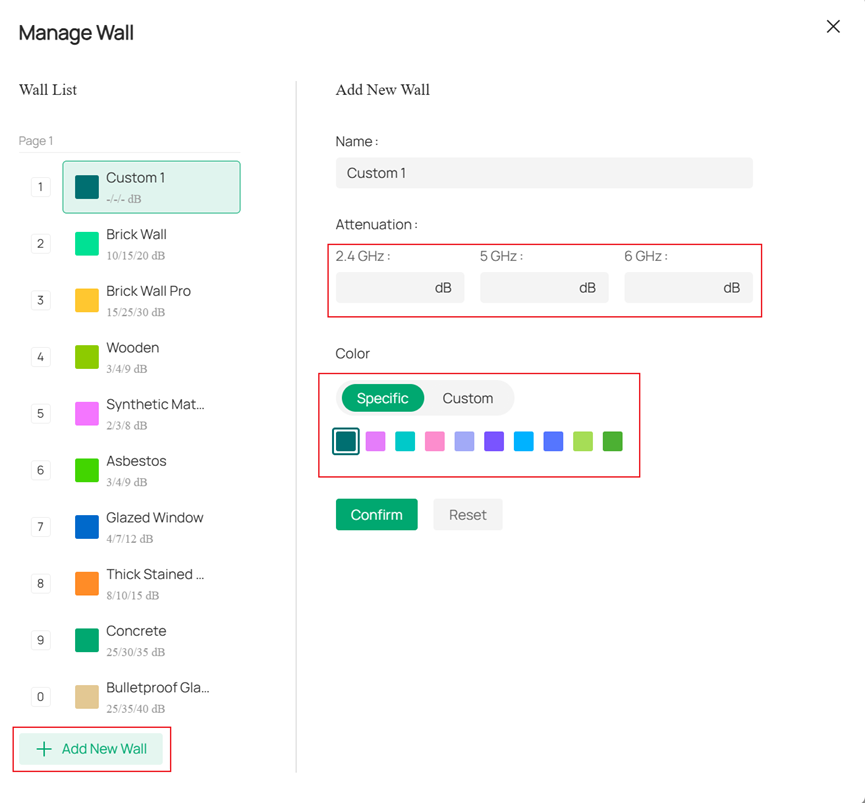
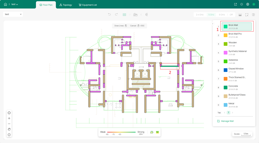
Of course, you can also click Manage Wall to create walls with custom attributes (the attributes of preset walls cannot be changed), and manually edit the attenuation of the walls on wireless signals, as well as the wall color:
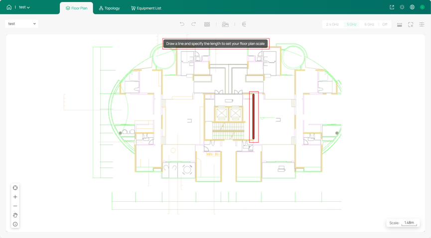
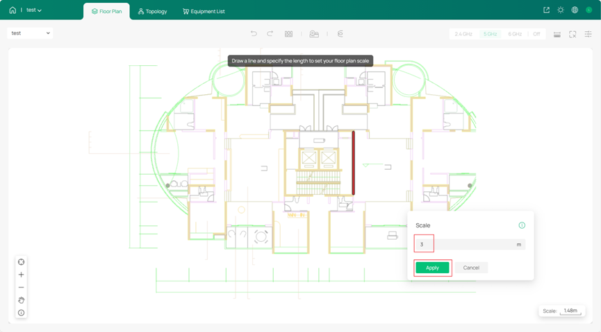
Step 4. Set the scale of the floor plan
You can draw a line in the diagram and specify its length. Then, Omada Design Hub will automatically measure the lengths of walls in the floor plan based on this line's length. Note that this line will not be retained afterwards. If you need to adjust the scale, you can click Scale in the bottom-right corner and draw a new line to set the length.
You can click on each section of the wall to view the wall length calculated by Omada Design Hub.
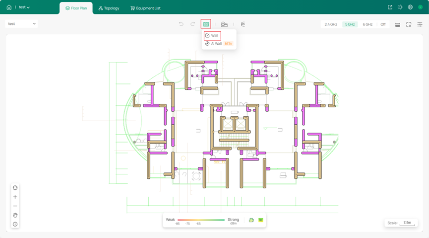
Step 5. Edit walls in the Floor Plan after importing the file.
In Step 3, after editing the wall attributes of the layers and confirming, you can manually create wall structures and select wall attributes in the Floor Plan, adding walls by drawing lines in the diagram.
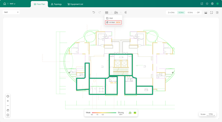
You can also choose the AI Wall function, but please note that the AI wall recognition process will remove the existing walls. After generation, you can click on each wall segment to individually adjust its attributes.
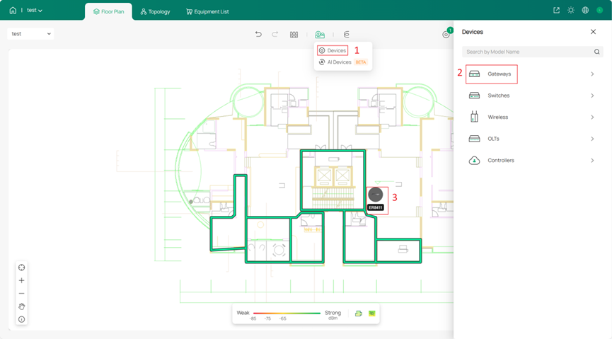
Step 6. Place the device
Select the devices you need and place them in suitable locations.
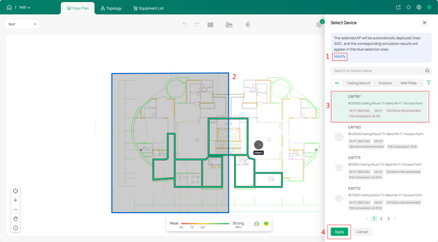
You can also choose to use the AI Device function. Currently, only EAP models are available for AI Device. Select the device you wish to use. The selected AP will be automatically deployed (max 300), and the corresponding simulation results will appear in the blue selection area. Of course, you can adjust this blue area by clicking on Modify.
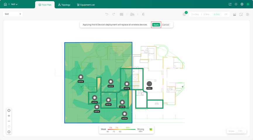
After selecting the area where APs need to be deployed, the AI will use algorithms to place the devices in optimal positions. You can click Apply to use the AI-generated layout results to the Floor Plan. Note that applying the AI Device's deployment will replace all wireless devices in the entire Floor Plan.
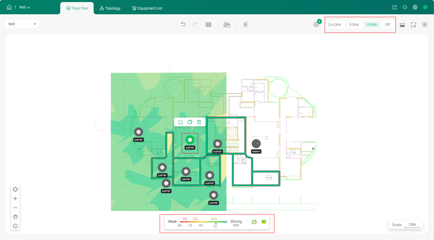
If the AI-generated layout results slightly differ from your needs, you can manually add new devices to the floor plan or click on an AP in the AI layout and then click the delete icon to remove it.
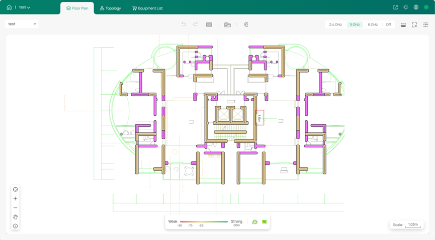
After the AI finishes deploying the devices, you can select the specific wireless frequency to view in the upper right corner. Then, by hovering your mouse over a location, you can see the wireless signal strength from the indicator at the bottom.
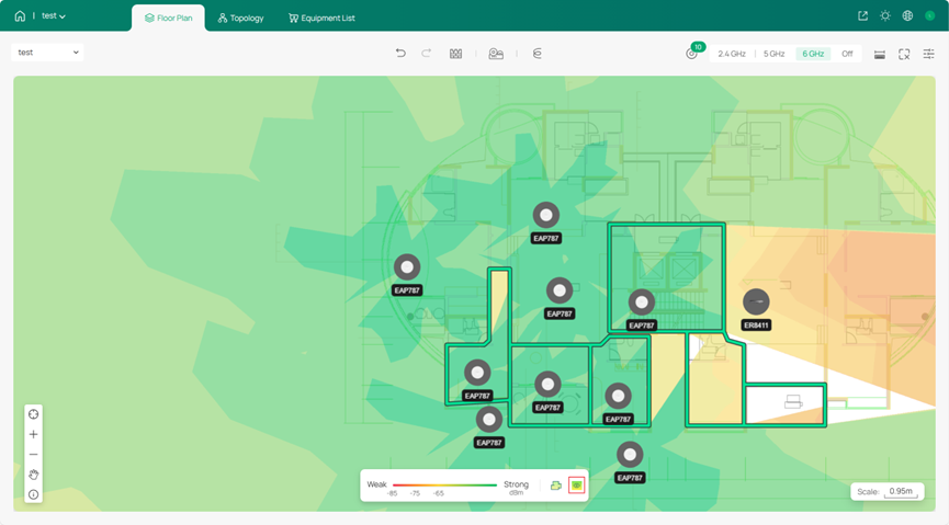
You can click the eye icon below to switch the display range of the signal coverage. When the eye icon is closed, it shows only the signal strength within the boundary; when the eye icon is open, it displays the signal strength across the entire floor plan.
Conclusion
This article demonstrates the specific steps and considerations for importing DXF files into the Omada Design Hub, and also provides an introduction to wall design and device placement within the Design Hub.
Get to know more details of each function and configuration please go to Download Center to download the manual of your product.
