


Contents
Objective
This guide provides instructions for configuring boundaries and toggling bounded/ boundless simulation modes in Omada Design Hub.
Requirements
- Omada Design Hub
Introduction
Omada Design Hub is an intelligent network planning tool that simplifies operations through smart AI tools, providing precise network solutions for small and medium-sized enterprises and system integrators.
In Omada Design Hub, it supports automatic identification of area boundaries in floor plans. And you can manually define the boundaries of the AI Devices and Simulation Boundary. And you can toggle between the bounded/boundless modes at any time—the simulation effect will switch in real time.
Configuration
Step 1. Login to Omada Design Hub with your TP-Link ID.

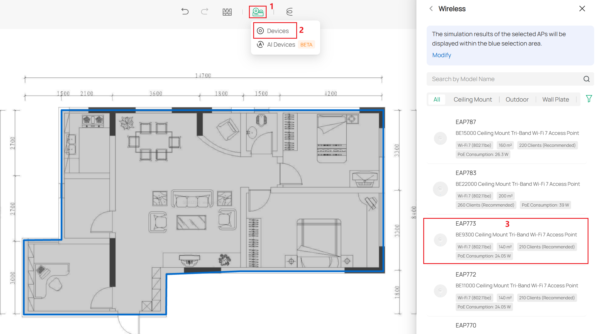
Step 2. You can find the devices in the top tab to choose the devices for deployment. As you deploy devices, the existing boundaries will be displayed.
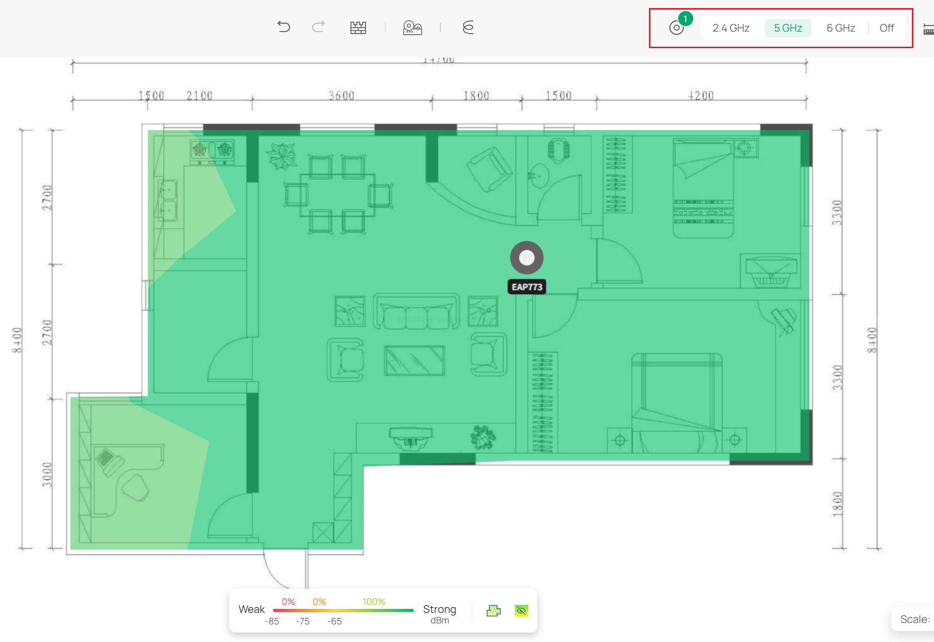
Step 3. Enter your floor plan and select a band to simulate by clicking the tab in the upper right corner.
Step 4. Click the Boundary icon in the lower tab to activate the Boundary Configuration window.

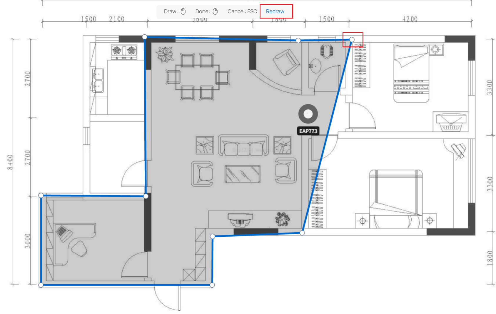
Step 5. Click Edit Boundary to edit the existing boundary.

Step 6. You can drag the endpoints to change the existing boundary or click Redraw to clear the boundary and redraw it. When you have finished editing the boundary, right-click to be done.
Step 7. If you need to restore the simulation boundary to the default recognition, click Re-identify to automatically get a boundary and edit it based on this border.


Step 8. You can click the Eye icon in the lower tab to switch modes to view simulation results with and without boundaries.

Step 9. You can find the AI Devices in the top tab to use AI-automated deployment devices.
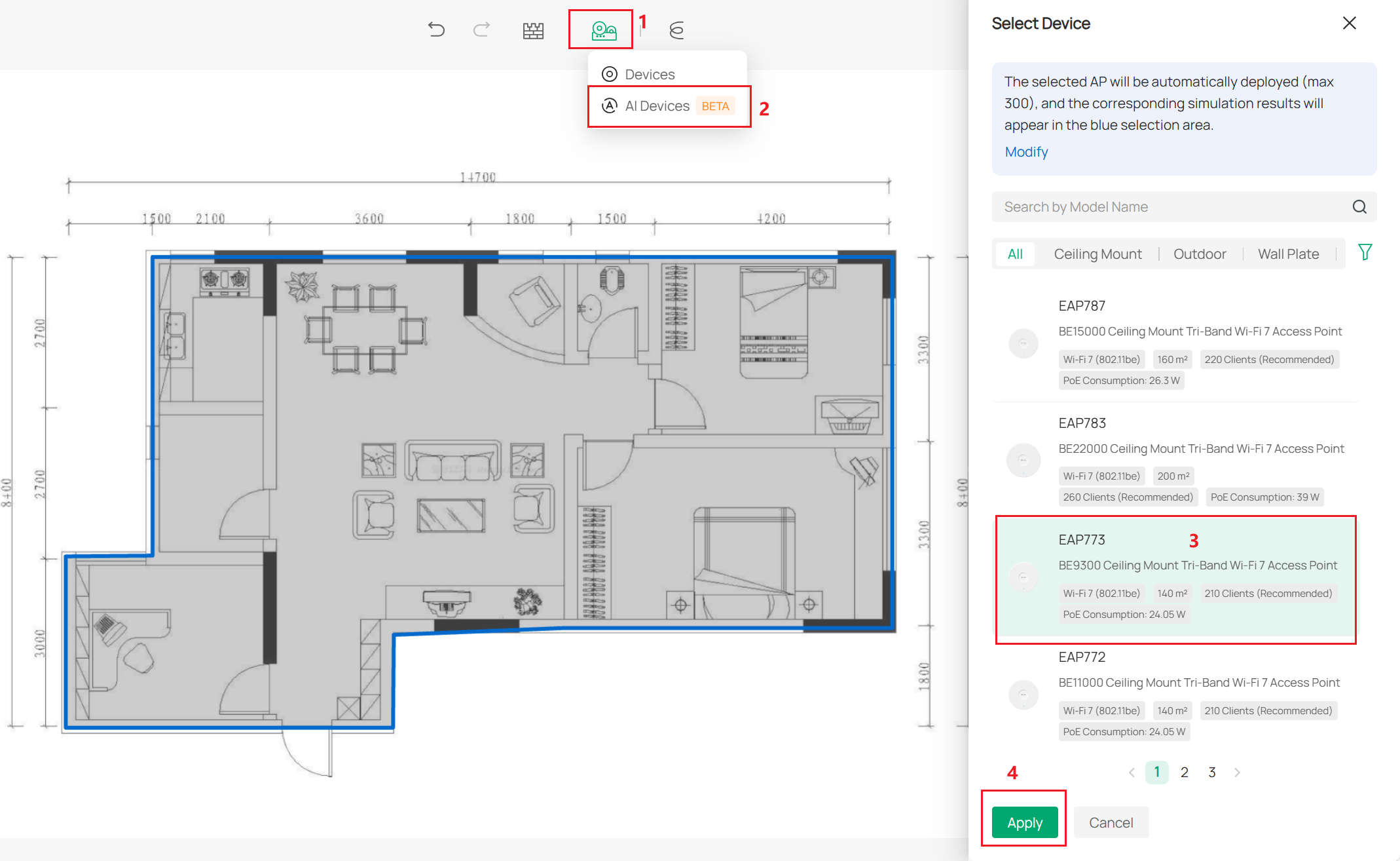
Step 10. While the AI automatically deploys the devices, it will display the current boundaries. (Automatic device deployment will only be done within the boundary) If you are not satisfied with the current boundaries, you can immediately edit them.

