


Overview
Policy-Based Routing (PBR) is an advanced routing technique that allows network devices to make forwarding decisions based on predefined policies rather than relying solely on the destination IP address in the routing table.
In traditional routing, packets are forwarded based on the best match in the routing table (longest prefix match). However, PBR overrides this behavior by inspecting additional
parameters such as source IP address, destination IP, protocol, or application type, and then directing traffic through a specific path.
This enables granular control over how traffic flows through the network. For example,
traffic from one subnet can be sent through a particular gateway, while another subnet uses a different path—even if both are trying to reach the same destination.
PBR is commonly used for:
- Traffic engineering
- Load distribution across multiple links
- Policy enforcement (e.g., sending specific traffic through a firewall or secure gateway)
- Multi-ISP environments
In essence, PBR gives administrators the flexibility to control routing decisions based on business or technical requirements, rather than being restricted to standard destination-based routing logic.
Topology Explanation
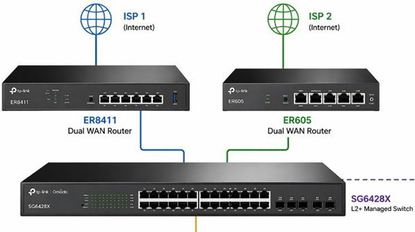
- SG6428X (L3 Switch)
- Acts as the default gateway for all user VLANs
- Performs inter-VLAN routing
- Applies PBR policies
- ER8411 Router (ISP 1)
- Connected via VLAN 1 (Transit Network)
- Switch IP: 10.56.1.234
- ER8411 IP (Next-Hop): 10.56.1.1
- ER605 Router (ISP 2)
- Connected via VLAN 249 (Transit Network)
- Switch IP: 11.56.1.5
- ER605 IP (Next-Hop): 11.56.1.1
- VLAN250 traffic → Routed via ER8411 (ISP 1)
- VLAN251 traffic → Routed via ER605 (ISP 2)
Key Concept (Very Important)
- ACL = Traffic Matching (WHO to match)
- Redirect Next Hop = Forwarding Decision (WHERE to send traffic)
Step-by-Step Configuration
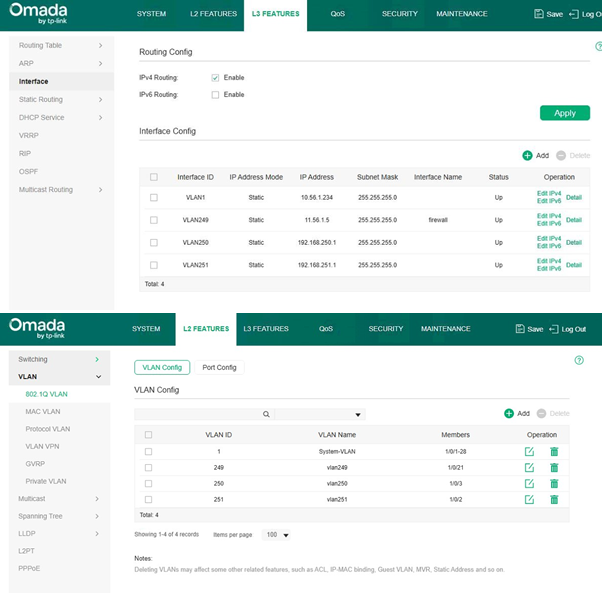
- Configure VLAN Interfaces (SVI on Switch)
Navigate to:
L3 Features → Interface
Create/Verify:
-
- VLAN1 → 10.56.1.234/24
- VLAN249 → 11.56.1.5/24
- VLAN250 → 192.168.250.1/24
- VLAN251 → 192.168.251.1/24
✔ Ensure all interfaces are UP
✔ SG6428X must be the default gateway for VLAN250 & VLAN251
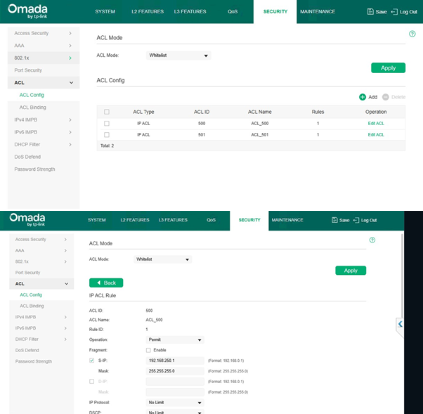
- Create IP ACLs (Traffic Matching)
Navigate to:
Security → ACL → ACL Config
ACL for VLAN250 (ER8411 Traffic)
-
- ACL ID: 500
- Operation: Permit
- Source IP: 192.168.250.0
- Mask: 255.255.255.0
-
- Destination: Any (leave blank)
ACL for VLAN251 (ER605 Traffic)
-
- ACL ID: 501
- Operation: Permit
- Source IP: 192.168.251.0
- Mask: 255.255.255.0
- Destination: Any (leave blank)
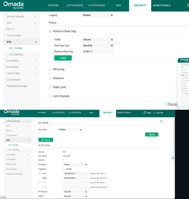
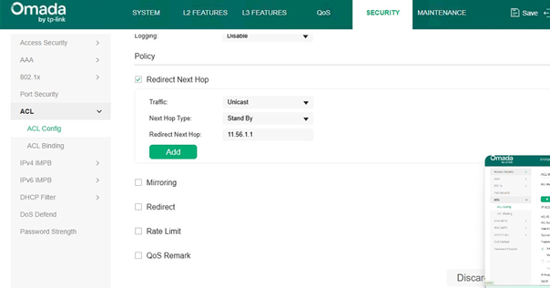
- Configure Redirect Next Hop (PBR Action)
Inside ACL → Edit Rule → Policy Section
VLAN250 → ER8411 (via VLAN1)
Enable:
✔ Redirect Next Hop Set:
-
- Traffic: Unicast
- Next Hop Type: Standby
- Redirect Next Hop: 10.56.1.1 (ER8411)
VLAN251 → ER605 (via VLAN249)
Enable:
✔ Redirect Next Hop Set:
-
- Traffic: Unicast
- Next Hop Type: Standby
- Redirect Next Hop: 11.56.1.1 (ER605)
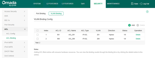
- Bind ACL to VLANs
Navigate to:
Security → ACL → ACL Binding → VLAN Binding
Bind:
|
ACL ID |
VLAN |
Direction |
|
500 |
VLAN250 |
Ingress |
|
501 |
VLAN251 |
Ingress |
✔ Direction must be Ingress
- Enable ACL Mode
Navigate to:
Security → ACL
-
- Set ACL Mode = Whitelist
- Click Apply
Traffic Flow Explanation
VLAN250 → ISP 1 (ER8411 Path)
Client (192.168.250.x)
→ SG6428X (GW: 192.168.250.1)
→ ACL Match
→ Redirect → 10.56.1.1 (ER8411 via VLAN1)
→ ISP 1 → Internet
VLAN251 → ISP 2 (ER605 Path)
Client (192.168.251.x)
→ SG6428X (GW: 192.168.251.1)
→ ACL Match
→ Redirect → 11.56.1.1 (ER605 via VLAN249)
→ ISP 2 → Internet
Critical Requirements
-
- Switch must be default gateway
- Next-hop must be in directly connected VLAN
- Routers must have return routes
VLAN & IP Addressing Plan
|
VLAN |
Purpose |
Subnet |
Switch IP (Gateway) |
Next Hop Device |
|
VLAN1 |
Transit to ER8411 |
10.56.1.0/24 |
10.56.1.234 |
ER8411 (10.56.1.1) |
|
VLAN249 |
Transit to ER605 |
11.56.1.0/24 |
11.56.1.5 |
ER605 (11.56.1.1) |
|
VLAN250 |
User VLAN |
192.168.250.0/24 |
192.168.250.1 |
ER8411 |
|
VLAN251 |
User VLAN |
192.168.251.0/24 |
192.168.251.1 |
ER605 |
Best Practices
✔ Use dedicated transit VLANs (VLAN1 & VLAN249)
✔ Apply ACL in Ingress direction
✔ Keep rules simple (source-based)
✔ Ensure return path exists
✔ Validate with traceroute
Common Mistakes
❌ Missing return route
❌ ACL applied on wrong VLAN
❌ Switch not acting as gateway
❌ Using unnecessary destination filters
Conclusion
This design makes the SG6428X a central L3 gateway, enabling:
- Dual ISP routing
- VLAN-based traffic steering
- Efficient use of ER8411 + ER605
Traffic separation:
- VLAN250 → ER8411 → ISP 1
- VLAN251 → ER605 → ISP 2

