


How to Configure MP-BGP on Omada Campus Switches


Contents
Introduction
Multiprotocol Border Gateway Protocol (MP-BGP) is a significant extension to the standard BGP-4 routing protocol. Traditional BGP was originally designed solely to exchange IPv4 unicast routing information. However, in modern campus network architectures, this single functionality can no longer meet evolving demands. MP-BGP addresses this limitation by introducing the Address Family Identifier (AFI) and Subsequent Address Family Identifier (SAFI), allowing a single BGP session to carry routing information for various network protocols, including IPv6, multicast, and Layer 2/Layer 3 Virtual Private Networks (VPNs).
Currently, MP‑BGP on Omada Campus Switches supports the IPv6 unicast address family.
Requirements
- Omada Campus Switches (with firmwar adapted to Omada Network 6.2 or above)
Configuration
The following example demonstrates the configuration of MP-BGP on Omada Campus switches in standalone mode.
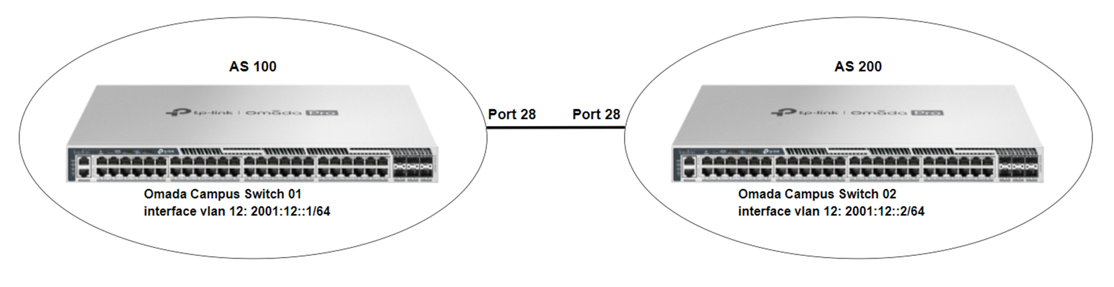
Configuration on Switch 01
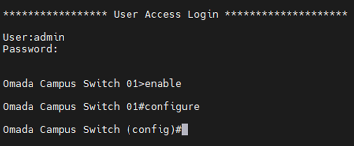
Step 1. Access the switch’s CLI via serial port, SSH, or Telnet, and enter the configuration mode.
Step 2. Use the following command to create VLAN 12 and add specific ports to VLAN 12.
#vlan 12
#interface twentyFive-gigabitEthernet 1/0/28
#switchport general allowed vlan 12 tagged
Step 3. Use the following command to enable IPv6 routing.
#ipv6 routing
Step 4. Use the following command to create a VLAN interface for the new VLAN and configure the corresponding IPv6 global unicast address.
#interface vlan 12
#ipv6 enable
#ipv6 address 2001:12::1/64
Step 5. Use the following command to configure the autonomous system number, neighbor, and route redistribution.
#router bgp 100
#neighbor 2001:12::2 remote-as 200
#neighbor 2001:12::2 ebgp-multihop 1
#address-family ipv6 unicast
#redistribute connected
#neighbor 2001:12::2 activate
#exit-address-family
Configuration on Switch 02
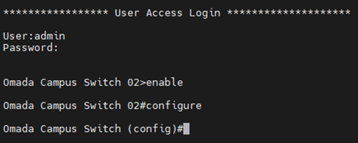
Step 1. Access the switch’s CLI via serial port, SSH, or Telnet, and enter the configuration mode.
Step 2. Use the following command to create VLAN 12 and add specific ports to VLAN 12.
#vlan 12
#interface twentyFive-gigabitEthernet 1/0/28
#switchport general allowed vlan 12 tagged
Step 3. Use the following command to enable IPv6 routing.
#ipv6 routing
Step 4. Use the following command to create a VLAN interface for the new VLAN and configure the corresponding IPv6 global unicast address.
#interface vlan 12
#ipv6 enable
#ipv6 address 2001:12::2/64
Step 5. Use the following command to configure the autonomous system number, neighbor, and route redistribution.
#router bgp 200
#neighbor 2001:12::1 remote-as 100
#neighbor 2001:12::1 ebgp-multihop 1
#address-family ipv6 unicast
#redistribute connected
#neighbor 2001:12::1 activate
#exit-address-family
Verification
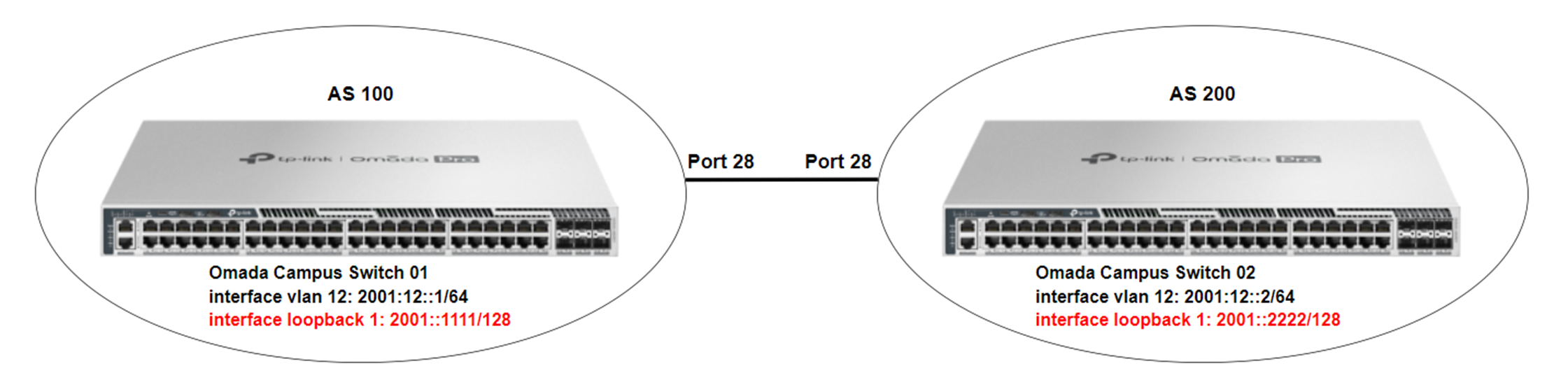
To verify that the MP-BGP is able to function properly and that routing information can be synchronized between different ASes, we can configure a loopback interface with an IPv6 global unicast address on each of the two switches.
Use the following command to configure a loopback interface on Switch 01:
#interface loopback 1
#ipv6 enable
#ipv6 address 2001::1111/128
Use the following command to configure a loopback interface on Switch 02:
#interface loopback 1
#ipv6 enable
#ipv6 address 2001::2222/128
Verification on Switch 01
1. Check whether the neighbor relationship has been established successfully.

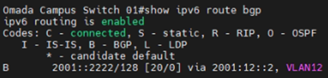
2. Check whether the BGP route entries have been added in Switch 01's IPv6 routing table
Verification on Switch 02
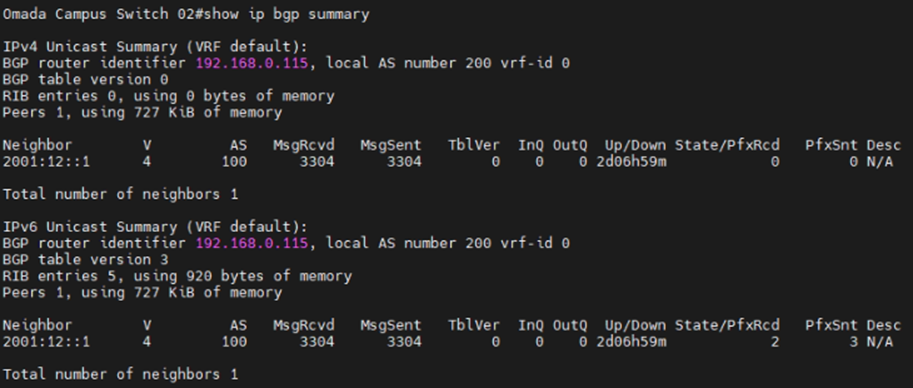
1. Check whether the neighbor relationship has been established successfully.
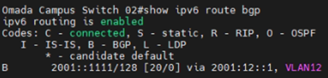
2. Check whether the BGP route entries have been added in Switch 01's IPv6 routing table
Conclusion
In this article, we briefly introduce MP-BGP and provide an example of configuring MP-BGP on Omada Campus Switches.
Get to know more details of each function and configuration please go to Download Center to download the manual of your product.
