


Contents
Configuration for Site-to-Site VPN
Introduction
The previous VPN interfaces were somewhat scattered. To simplify the complexity of VPN configuration, the interface logic has been redesigned starting from Controller version 6.2. This document will provide a step-by-step introduction.
Before configuration, please note the changes to the VPN pages:
1. VPN Configuration Page Changes:
- Navigate to Network Config > VPN > VPN page. The VPN configuration page is divided into three tabs: VPN Server, VPN Client, and Site-to-Site VPN. The VPN pages have been reorganized based on scenarios and VPN types.
- The SSL VPN within the VPN Server has been migrated and adjusted from the VPN > SSL VPN page, while the Wireguard Server page has been newly added.
- Additionally, WireGuard Client page has been added to the VPN Client page.
- Auto WireGuard has been added to the Site-to-Site VPN section, while Manual WireGuard has been relocated from the VPN > WireGuard page.
- VPN user information can be viewed under the VPN Server page when server entries exist.
- IPsec failover has been merged into the VPN Configuration page.
- SSL VPN's Resource Management, User Group, etc., are now located on the User Management page.
2. VPN Status Page Changes:
Navigate to Network Config > VPN Status, where three tabbed pages will be displayed: VPN Server, VPN Client, and Site-to-Site VPN.
Requirements
- Omada Controller v6.2 and above
- Omada Gateway
Configuration
Configuration for VPN Server
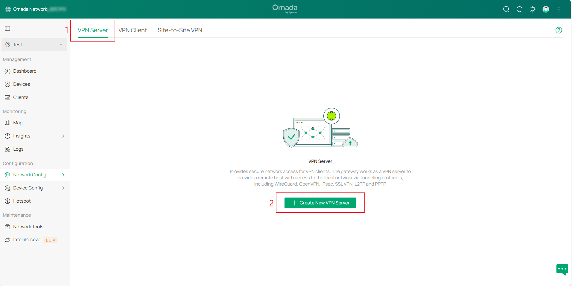
Step 1. Log in to the controller, navigate to Site view > Network Config > VPN > VPN Configuration page. The VPN Configuration page is divided into three tabs: VPN Server, VPN Client, and Site-to-Site VPN. Go to VPN Server page and click Create New VPN Server.
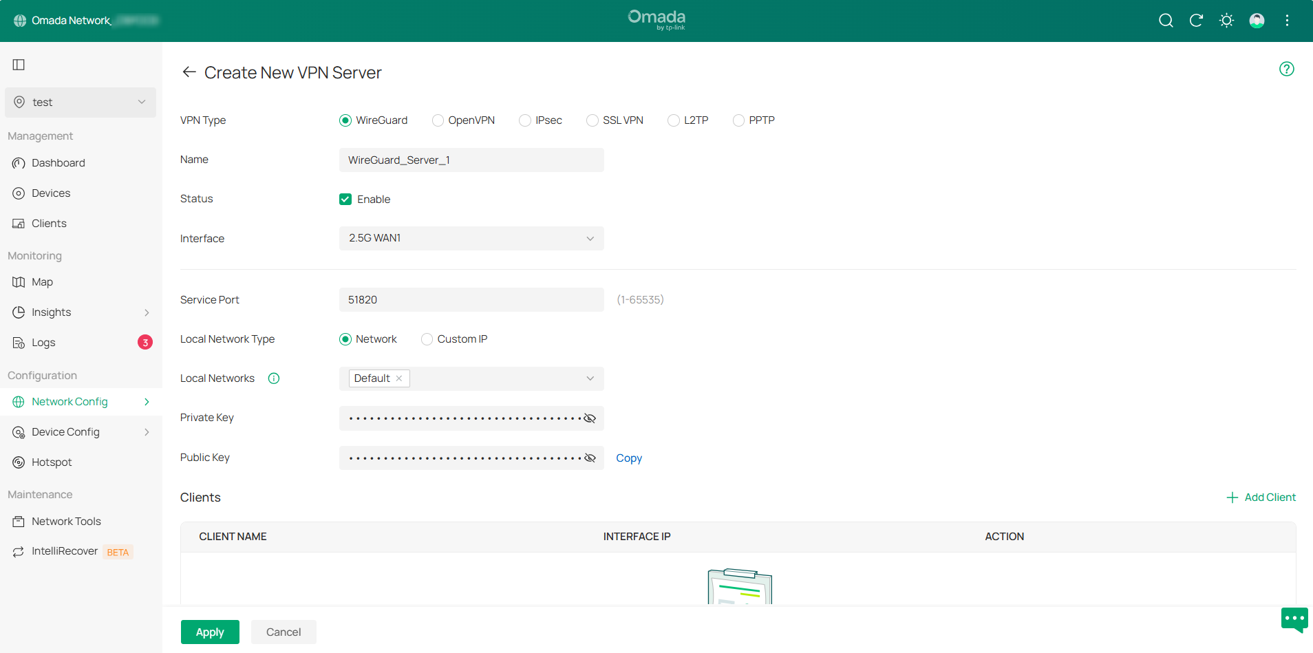
Available VPN types include WireGuard, OpenVPN, IPsec, SSL VPN, L2TP, and PPTP. Select the VPN type you need to configure. Some information will be auto-filled; modify and supplement as needed, then click Apply to create the entry.
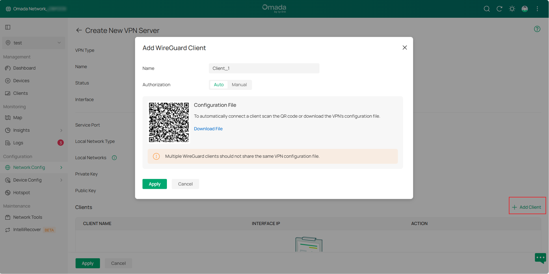
There are two methods to add clients to a WireGuard server: Auto and Manual. You may obtain the VPN client configuration either by scanning the QR code or downloading the file.
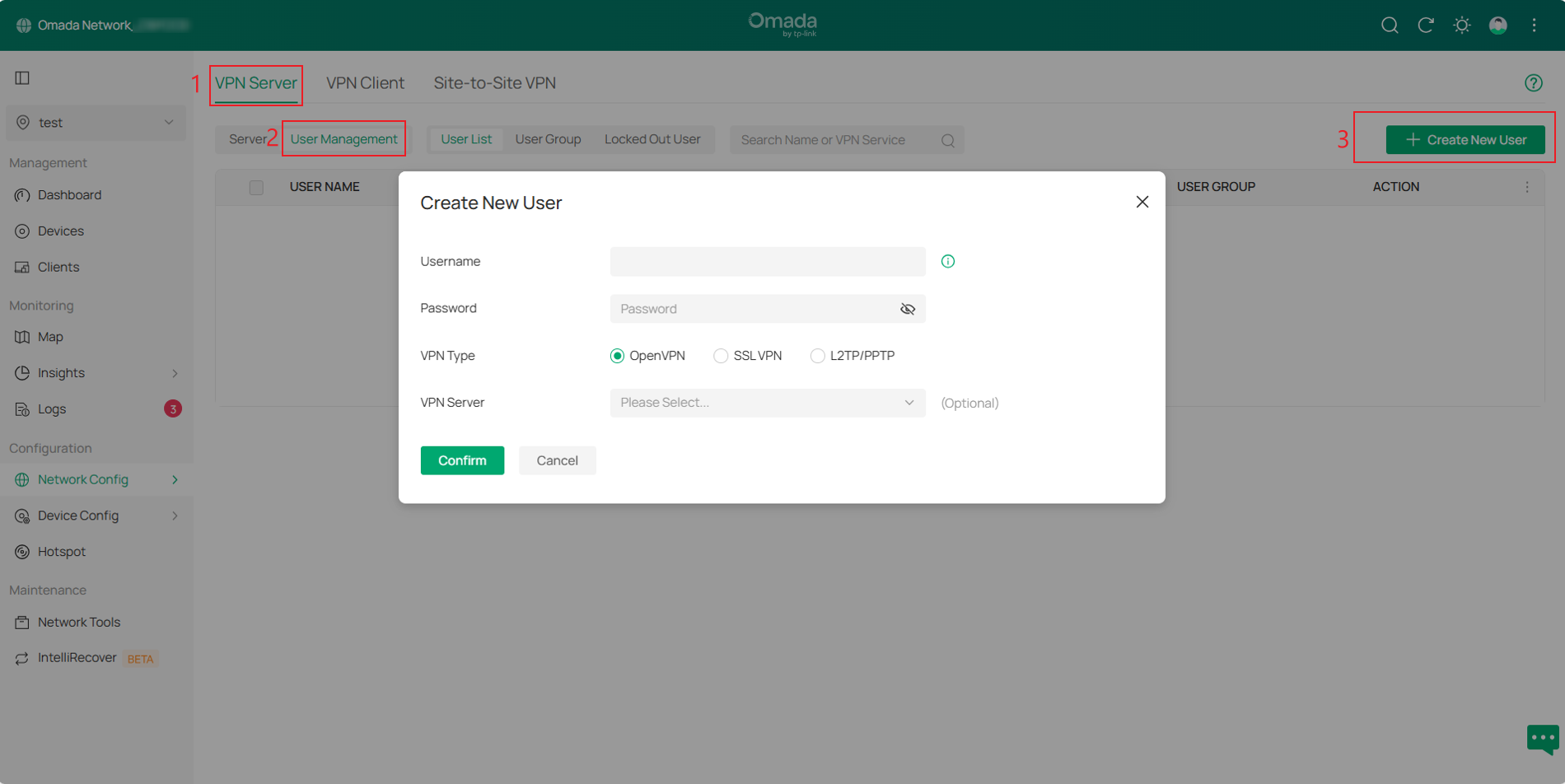
Step 2. For OpenVPN, L2TP, or PPTP using local authentication, you need to configure a VPN user. Navigate to VPN Server > User Management page and click Create New User.
Then, create a Username and Password. Select the desired VPN Type, choose the corresponding VPN Server, and click Confirm to create a VPN user.
Step 3. After configuration, you can select the desired VPN type on the Network Config > VPN > VPN Status > VPN Server page to view VPN tunnel status.
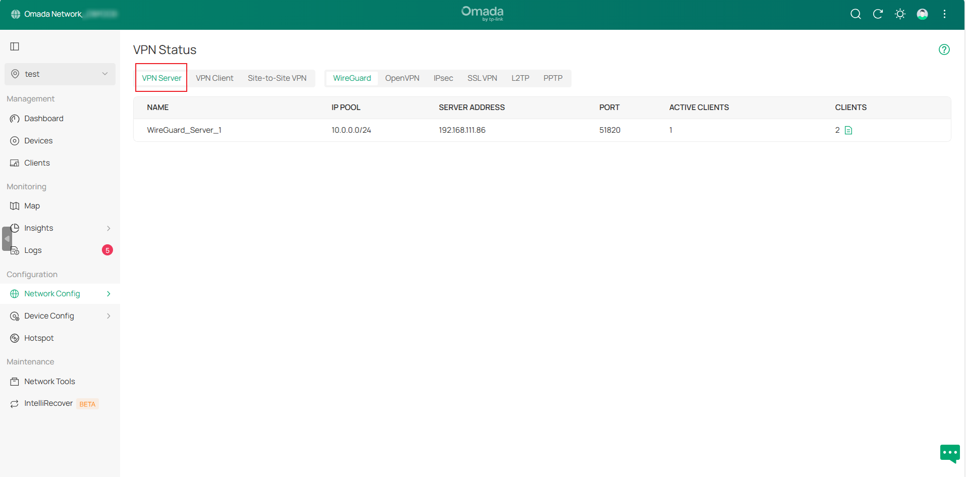
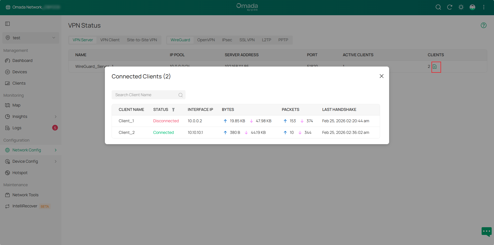
In the WireGuard VPN Server tunnel entry, click the Details button in the CLIENTS column to view detailed information.
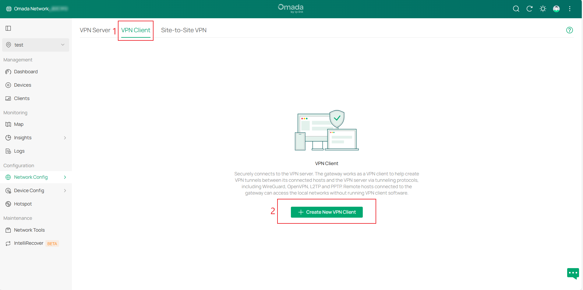
Configuration for VPN Client
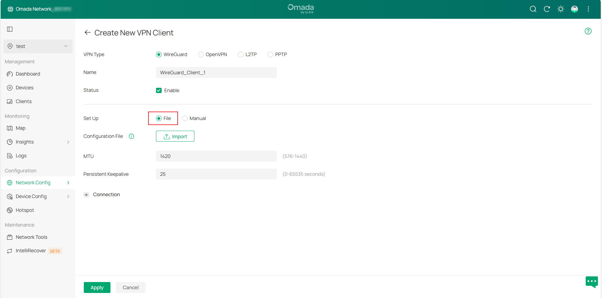
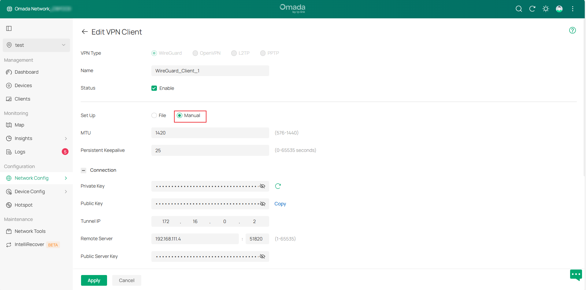
Step 1. Go to Network Config > VPN > VPN Client page and click Create New VPN Client, then select VPN Type to create an entry.
Available VPN types include WireGuard, OpenVPN, L2TP, and PPTP. WireGuard VPN Client configuration can be completed by uploading a configuration file or manually configuring settings.
Step 2. After configuration, go to VPN > VPN Status > VPN Client and select the corresponding VPN type to view the VPN tunnel status.
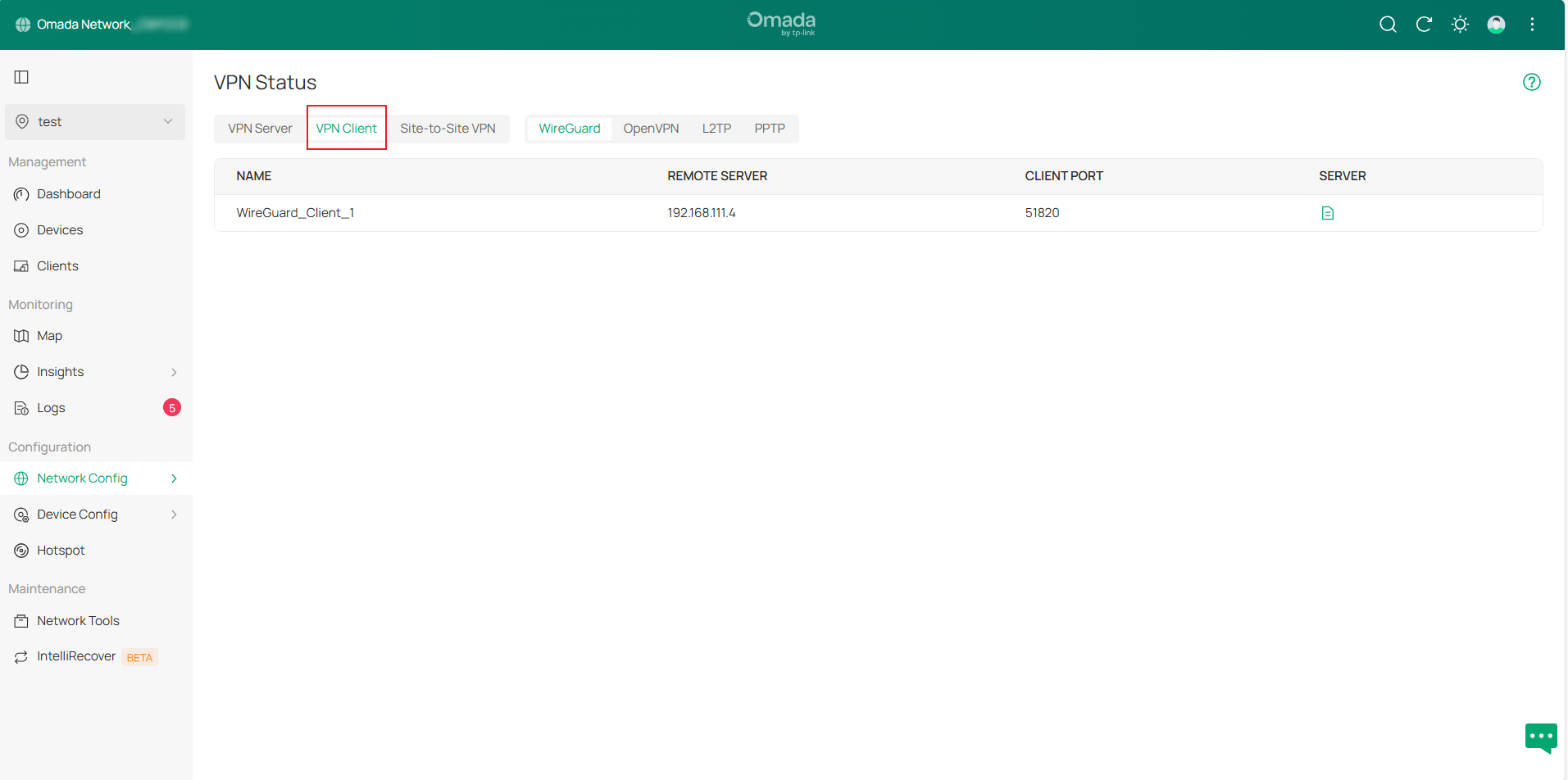
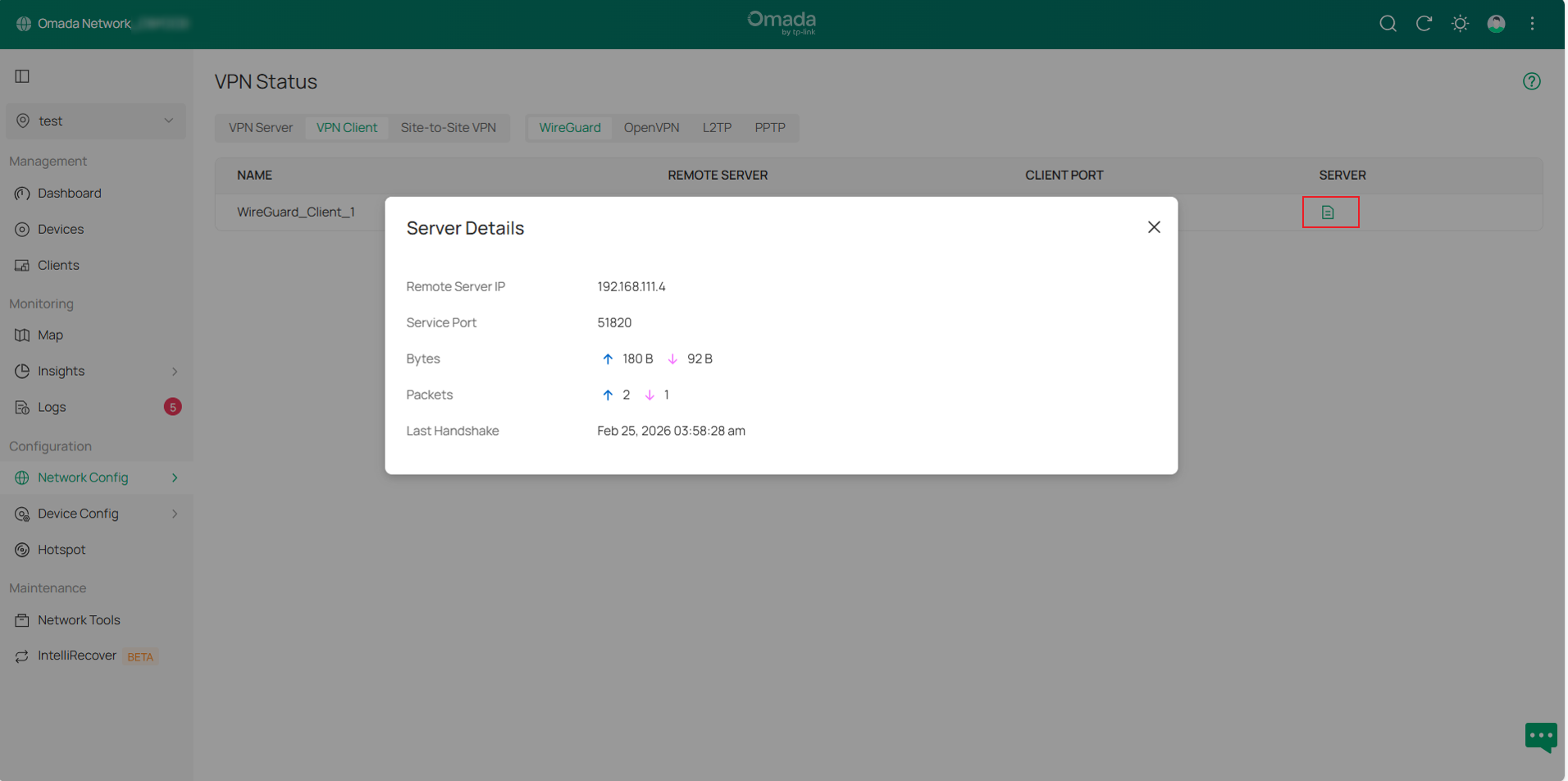
In the WireGuard VPN Client tunnel entry, click the Details button in the SERVER column to expand detailed information.
Configuration for Site-to-Site VPN
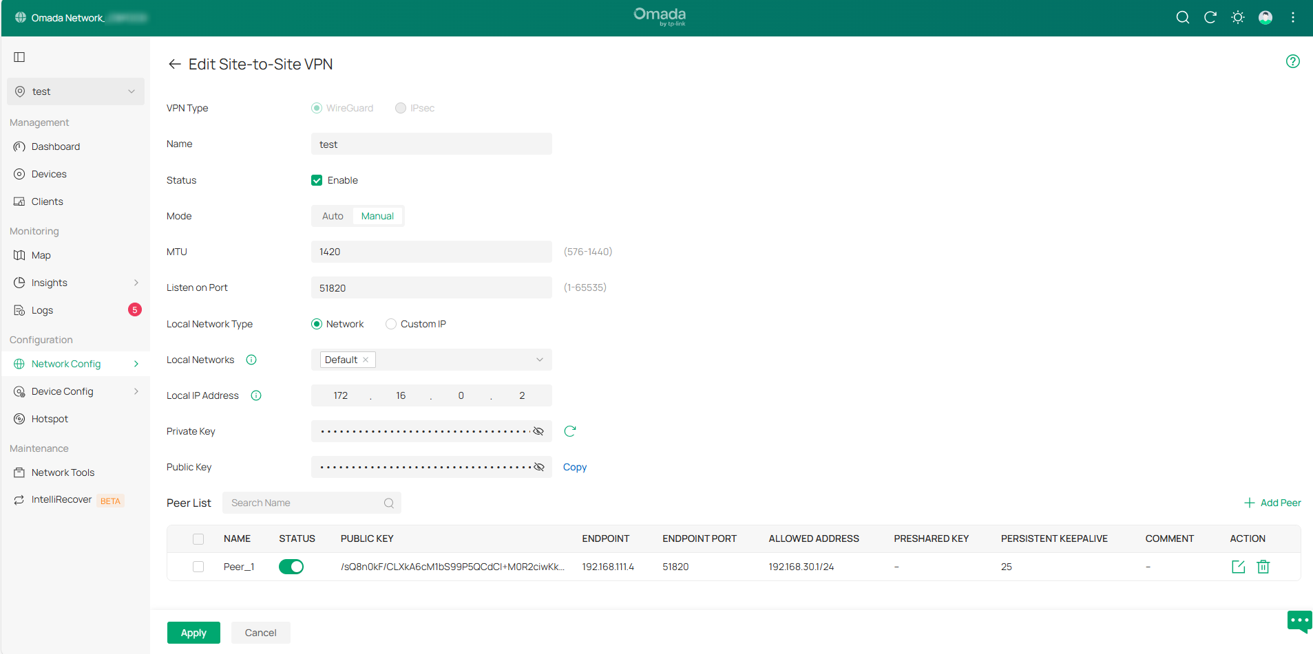
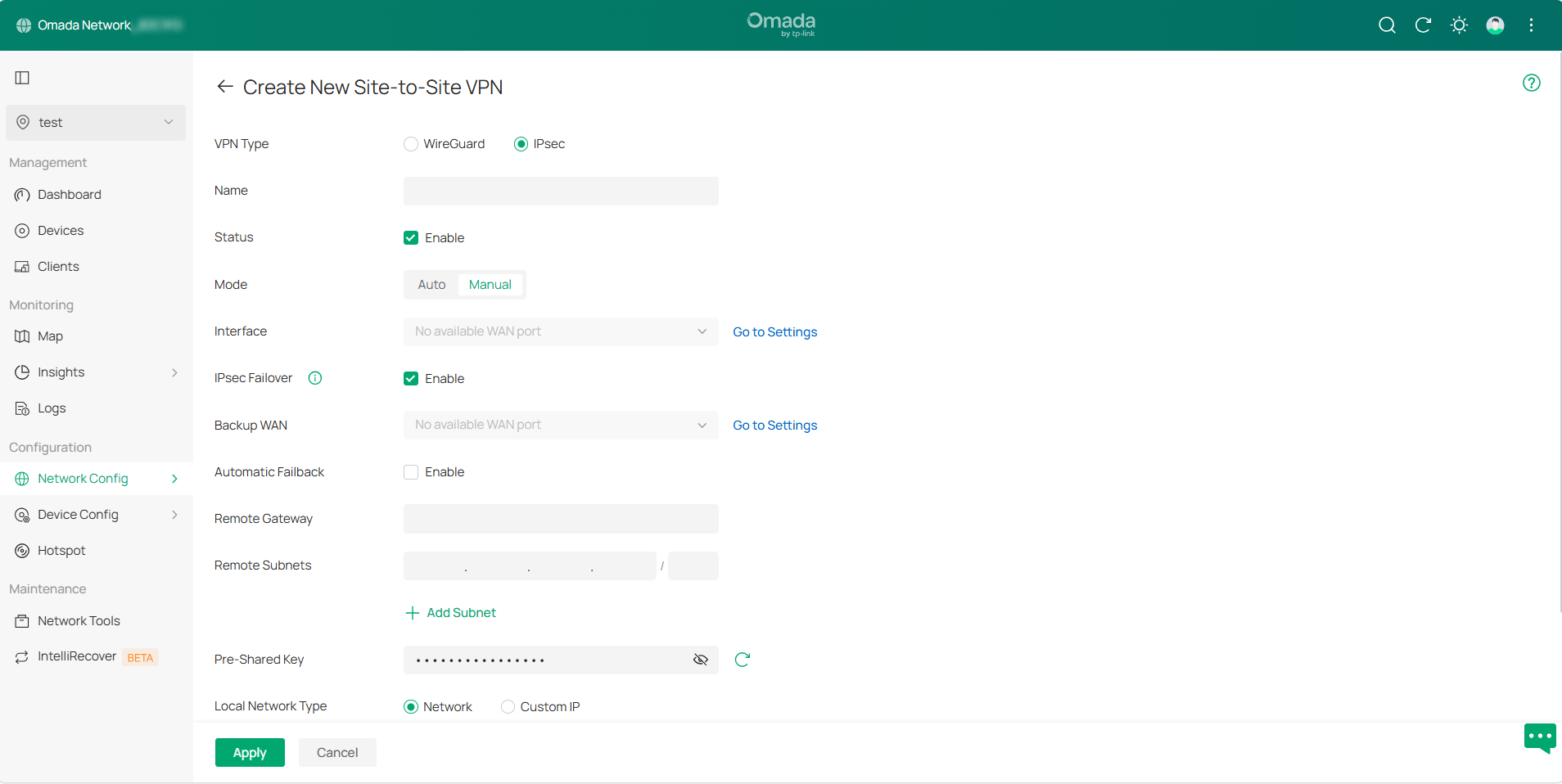
Step 1. Go to Network Config > VPN > Site-to-Site VPN page and click Create New Site-to-Site VPN, then select VPN Type to create an entry.
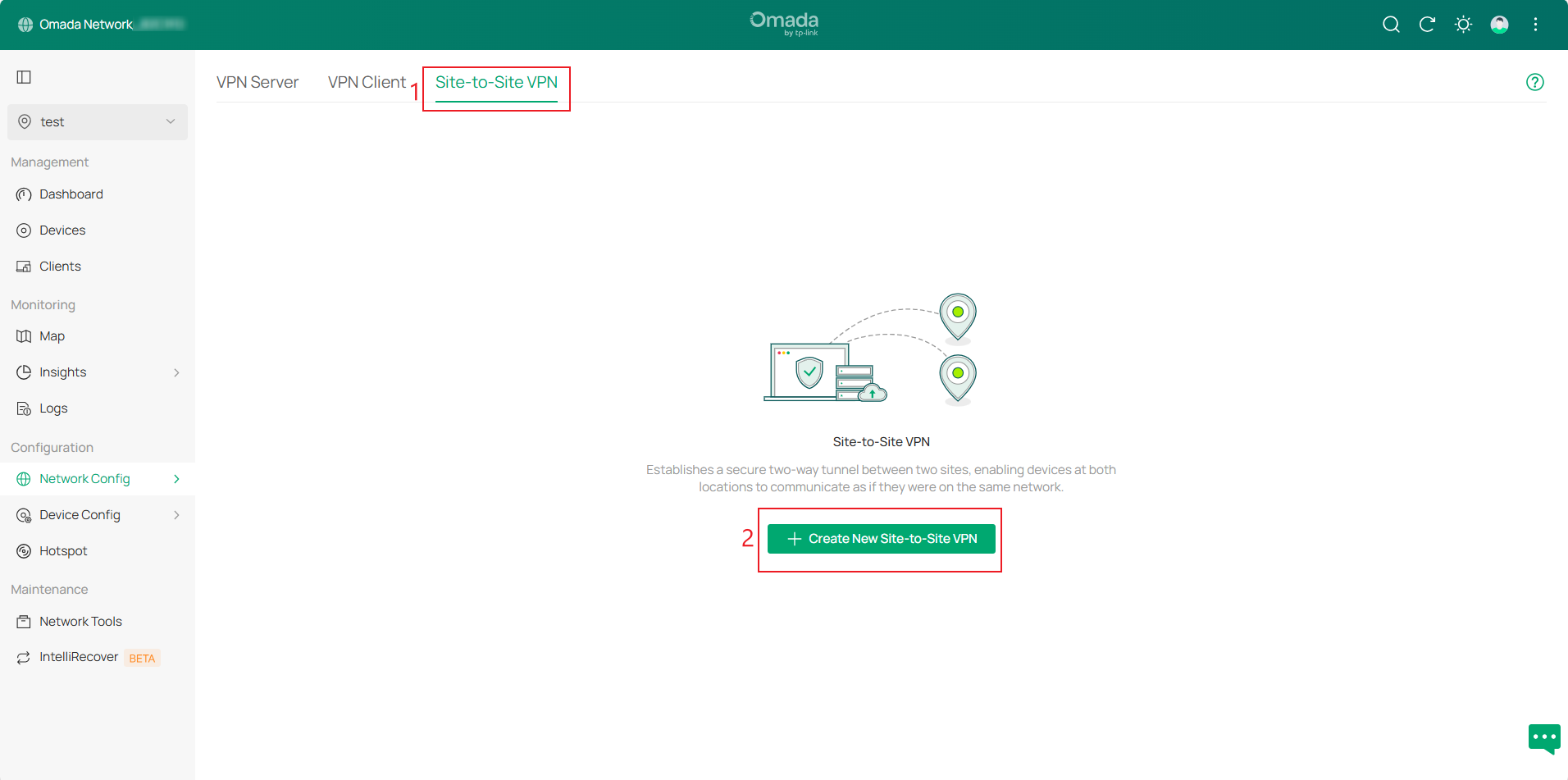
Available VPN types include WireGuard and IPsec. There are two configuration modes: Auto and Manual.
Controller v6.2 integrates IPsec Failover configuration into IPsec Manual mode and simplifies the configuration process. The Backup WAN refers to the WAN interface of the Secondary VPN entry. The IPsec Failover switch corresponds to the status of the Secondary VPN entry. Automatic Failback corresponds to the failover configuration.
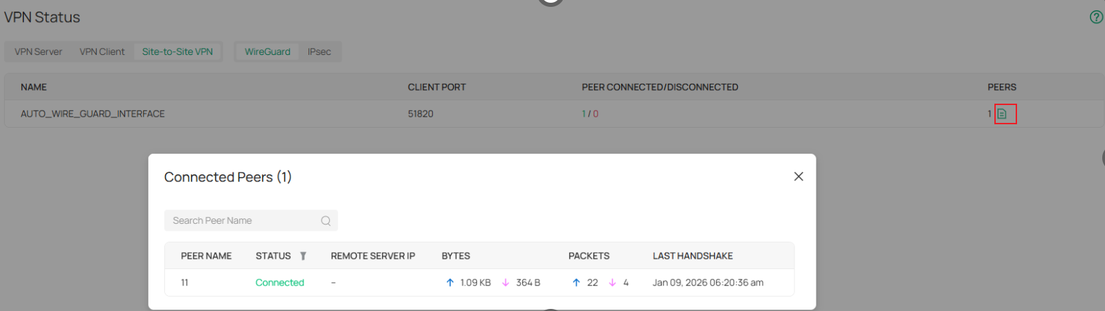
Step 2. After configuration, go to VPN > VPN Status > Site-to-Site VPN and select the corresponding VPN type to view the VPN tunnel status.
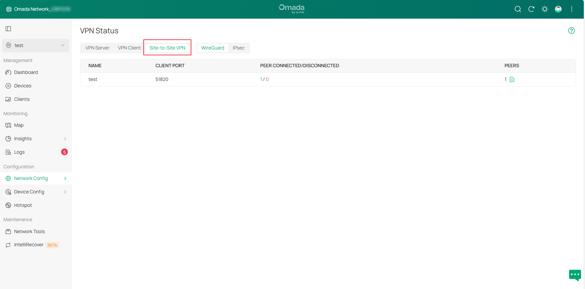
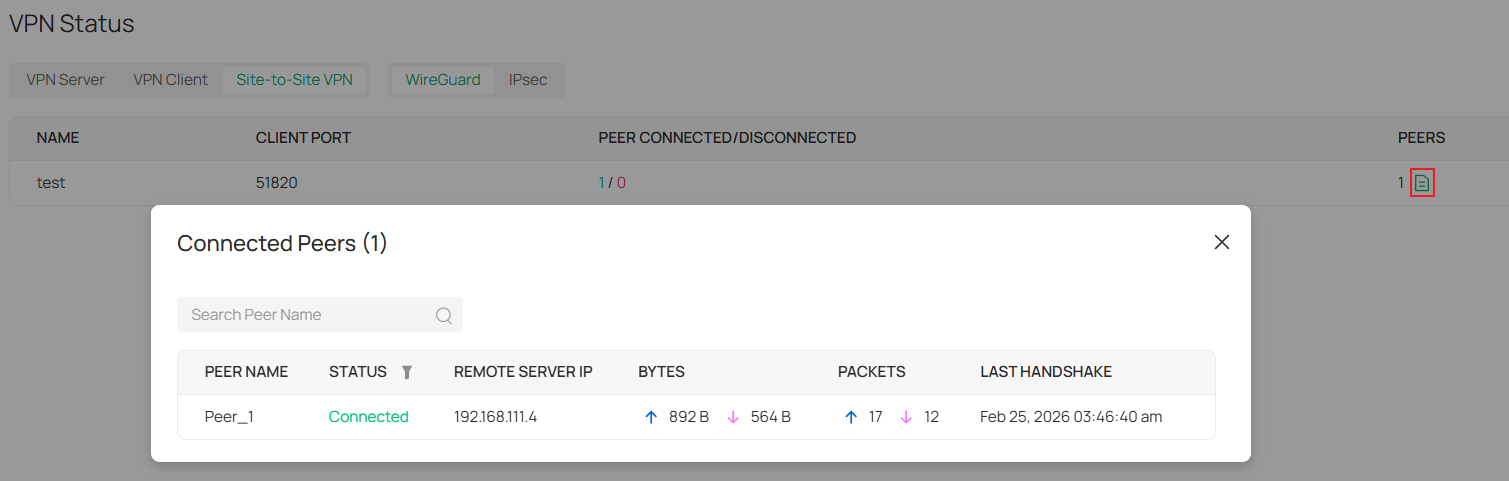
In manual mode, WireGuard VPN displays tunnel information as interface entries. For Auto mode, tunnel details appear under “AUTO_WIRE_GUARD_INTERFACE”. Click the Details button in the PEERS column to expand the information.
Configuration for SSL VPN
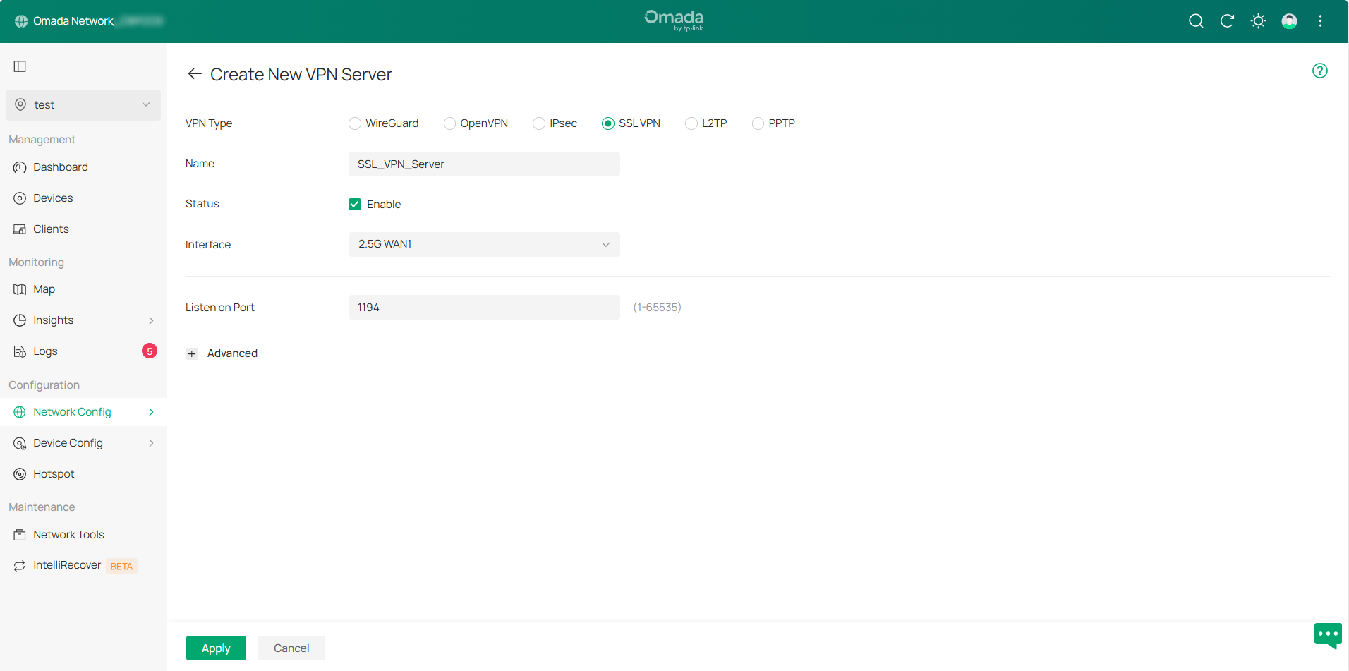
Step 1. Go to the VPN Server page and click Create New VPN Server, select SSL VPN as the VPN Type. The page will automatically populate the default configuration information. You can select the Interface and modify the relevant settings, then click Apply to save the configuration.
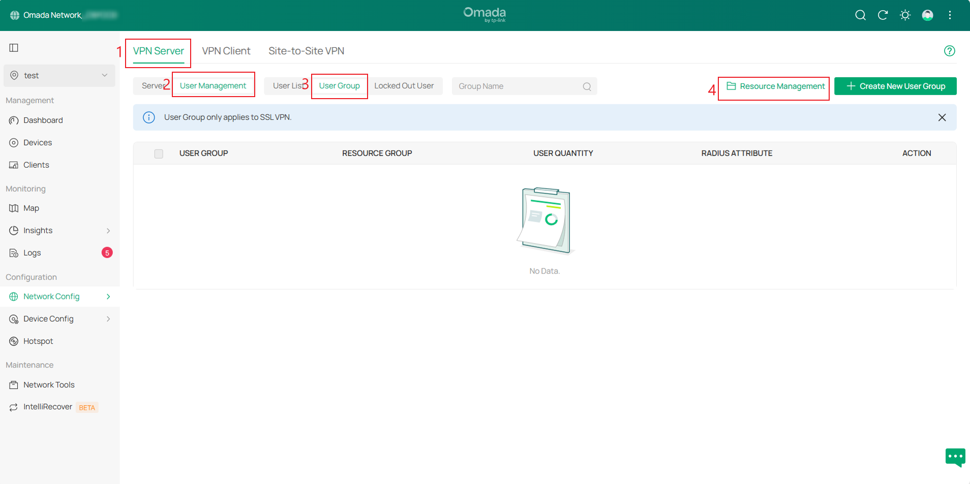
Step 2. Then go to VPN Server > User Management > User Group page, click Resource Management in the upper-right corner to create a Tunnel Resource.
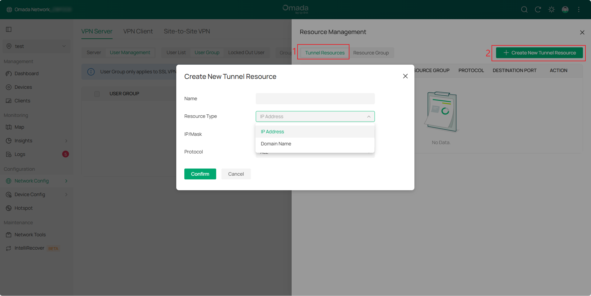
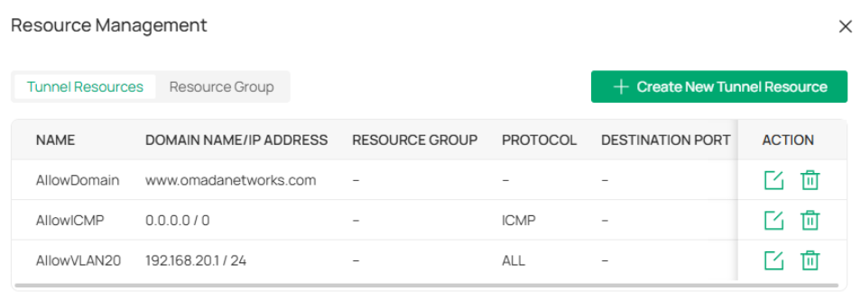
In the Resource Management page, click Create New Tunnel Resource. On this page, you can restrict resources by IP addresses and protocols, or by domain names.
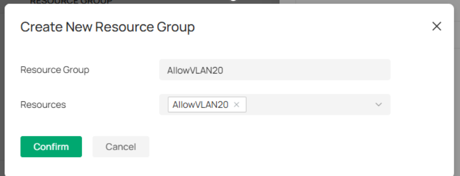
Then, click the Resource Group tab next to the Tunnel Resource, click Create New Resource Group, and apply the tunnel resources created to different resource groups.
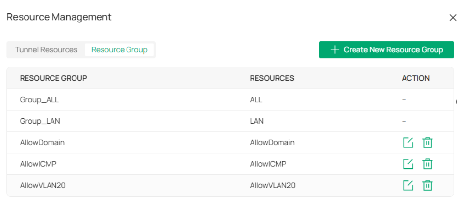
Note: There are two default resource groups: Group_LAN and Group_ALL. Group_LAN refers to all devices behind the Server, and Group_ALL also includes resources for accessing the Internet.
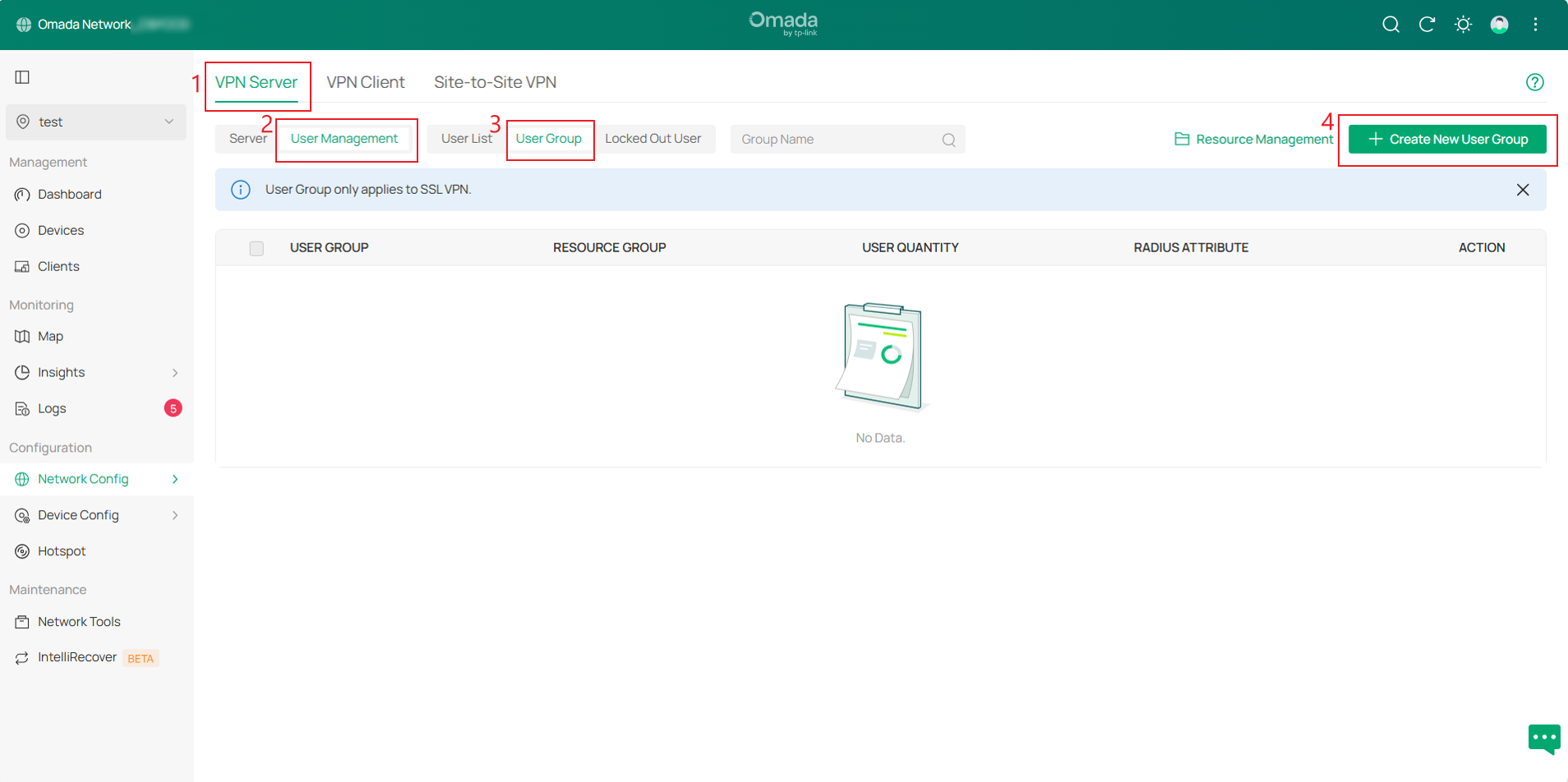
Step 3. Navigate to VPN Server > User Management > User Group page, then click Create New User Group in the upper-right corner.
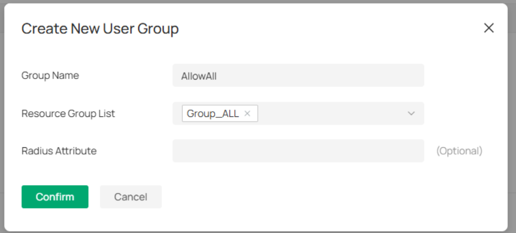
After configuration, click Confirm to save settings. The Radius Attribute is only effective in the Radius authentication mode. It maps the user group with radius grouping information (which is carried by the CLASS attribute 25).
Note: If you want to implement the proxy Internet access for clients, please select Group_ALL for the resource group.
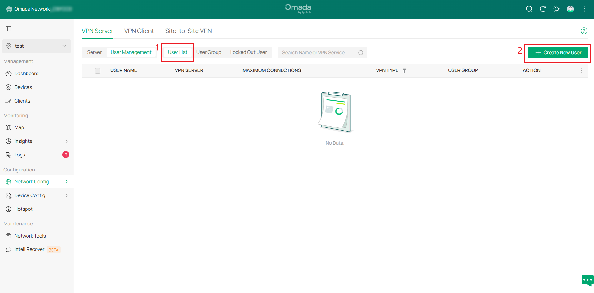
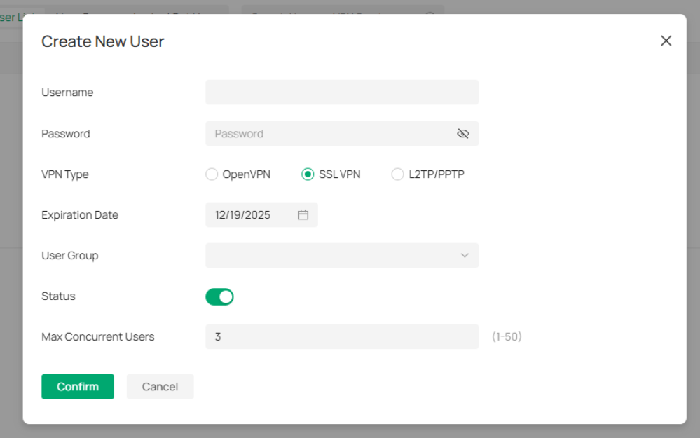
Step 4. Switch to the User List page and click Create New User in the upper-right corner. Then configure the Username and Password, select SSL VPN as the VPN Type, set the user Expiration Date, and choose the User Group created.
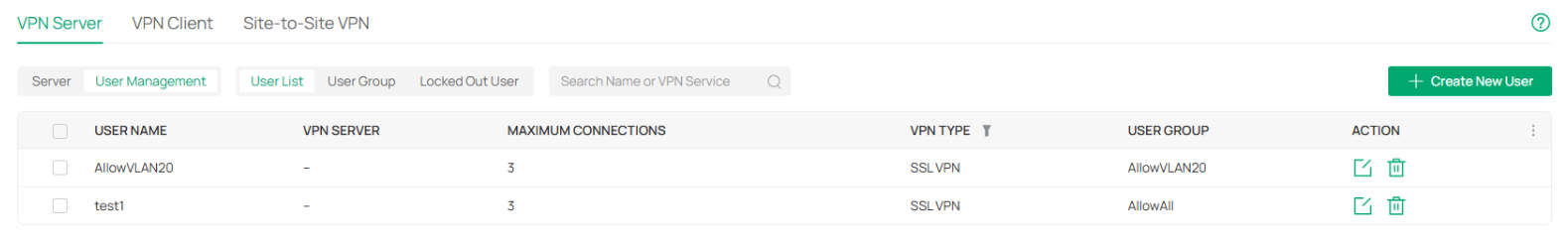
After creation, you can view the User list and repeat the previous steps to create multiple User entries.
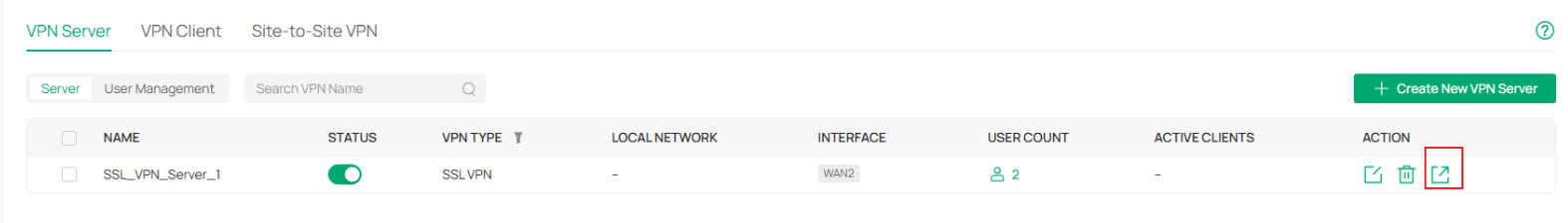
Step 5. Navigate to VPN Server > Server page and click the Export button to the right of the SSL VPN Server entry. After exporting, clients can use this certificate file to connect to the server.
Controller v6.2 removes the pop-up prompt for verifying the IP or domain name required to connect to the server in the certificate.
If “Custom Server” is selected, the configuration will use the custom server address entered. If not selected, the WAN IP selected in the entry will be used. If the WAN interface lacks an IP address, it will use 0.0.0.0.
When using OpenVPN without selecting “Custom Server” and without WAN IP address, the exported certificate will not include the server's IP address or domain name.
For other VPN configurations in controller mode, please refer to the following:
How to configure Wireguard VPN on Omada Gateway | TP-Link
How to configure OpenVPN on Omada Gateway via Omada Controller | TP-Link
How to set up Site-to-Site Manual IPsec VPN Tunnels on Omada Gateway via Omada Controller | TP-Link
How to set up PPTP & L2TP VPN Server with Omada Gateway in Controller Mode | TP-Link
How to set up PPTP & L2TP VPN client with Omada Gateway in controller mode | TP-Link
SSL VPN Verification
Use the OpenVPN GUI on the client to import the configuration file, enter the corresponding username and password to connect.
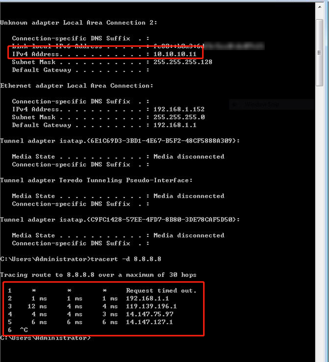
Account 1: VPN Client implements proxy Internet access through VPN Server.

After a successful connection, the server assigns the VPN client an IP address of 10.10.10.11. When the client accesses 8.8.8.8, the first hop is the VPN Tunnel. Because the data is encrypted, the corresponding IP address cannot be resolved. The second hop is the default gateway of the VPN Server, and all data of the client goes through the VPN Tunnel to realize proxy Internet access.
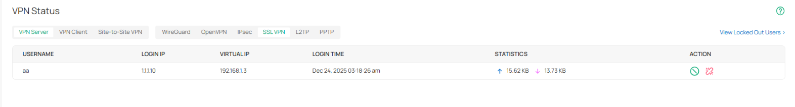
Navigate to Network Config > VPN > VPN Status > VPN Server page and click SSL VPN, client connection information will also be displayed here.
Account 2: VPN Client can only access VLAN 20, but cannot access VLAN 30.
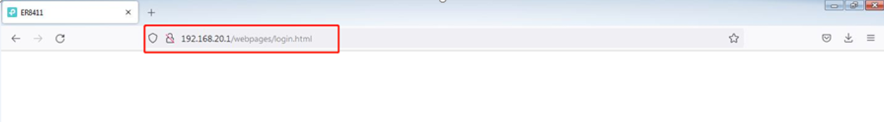
After a successful connection, the server assigns the VPN client an IP address of 10.10.10.12. The VPN client can ping the device in VLAN 20 (192.168.20.100), but cannot ping the device in VLAN 30 (192.168.30.100). At the same time, the management interface of the router can be accessed through 192.168.20.1.

Account 3: The VPN Client and the devices behind the Server can only interact through the ICMP protocol.
After a successful connection, the server assigns the VPN client an IP address of 10.10.10.13. The VPN client can ping the device in VLAN 20 (192.168.20.100) and the device in VLAN 30 (192.168.30.100). But the management interface of the router cannot be accessed through 192.168.20.1.


Conclusion
Now you know about the updates on the VPN page. You can create VPN as needed.
Get to know more details of each function and configuration please go to Download Center to download the manual of your product.
