


Contents
Overall Configuring Principles
Objective
This article will introduce how to configure the MLD Snooping on Omada Switches on the Omada SDN Controller.
Requirements
- Omada Access, Access Plus, Access Pro, Access Max, Aggregation and Campus switches
- Omada Controller (Software Controller / Hardware Controller / Cloud Based Controller, V5.9 and above)
Introduction
MLD Snooping (Multicast Listener Discovery Snooping) is an IPv6 Layer 2 multicast protocol that listens for multicast packets sent between multicast devices and user hosts to maintain the outbound port information of multicast packets and manage and control the forwarding of multicast data packets at the data link layer.
Application Scenario
The diagram shows a typical Hotel IPTV scenario, as we can see, the IPTV source is in the LAN. The IPTV source is connected to an access switch then to the aggregation switch so the multicast stream is able to hand out to all IPTV devices in LAN. Access switches connecting to the IPTVs are also connected to the aggregation switch.

How does the MLD system work
The MLD system consists of several parts: Multicast Source (IPTV Source), MLD Querier, MLD Snooping, MLD Receiver.

For our product, the device running MLD Snooping are the switches, and omada switch can also be configured as the MLD Snooping Querier.
In MLD Snooping, there are three kinds of MLD packets, the MLD Query, MLD Report and MLD Leave.
If the Multicast Source doesn’t support the query feature, it will simply broadcast all the streams which is a waste of network resource. Enabling MLD Snooping function will handle this.
The Querier will send MLD Query, which consists of general query and specific query. Here it’s usually general query, which will ask if there’s any device requesting for any multicast stream, and the MLD Query will be forwarded by the switches and finally reaches the MLD Receiver such as an IPTV.
If someone want to watch a certain channel, the IPTV will send a MLD Report, which includes the information of this channel to request for this stream, which will also join this multicast group.
When the user switch to another channel, which means the IPTV no longer needs this stream, it will send the MLD Leave to leave this multicast group.
For all the devices running MLD Snooping, there are two kinds of port roles to help creating multicast groups, the router port and the member port. For a switch, the port receiving the MLD Query packet will become the router port, and the ports receiving MLD Report/leave will become the member port.
You can also assume that the router port is the port closest to the querier on a switch, and the member ports are the ports closest to receivers. So after the query process mentioned previously, the switch running MLD Snooping will create multicast groups, including the multicast IP of this stream, the VLAN this stream is running in, and the ports participating in this group, including the router port and the member port.
As mentioned before, the multicast source will simply broadcast the stream in the network. After the multicast groups created, the switch will only forward the corresponding multicast stream only to the router port and member ports. And the MLD Report/Leave packets will only be forwarded from member port to the router port.
Overall Configuring Principles
Here we will introduce several overall configuring principles for MLD Snooping, taking the previous topology as an example. These are some recommendations we made when configuring MLD Snooping, which will help avoid misfunction and improve device efficiency, bringing a better user experience.
- Disable MLD featuers for router.
As the IPTV source is included in the LAN in such a hotel IPTV scenario, so the multicast stream will not be entering from WAN side, and the router will actually not participate in the whole MLD process.
If you enable the MLD feature on the router, then it will be recognized as a querier, so the switch port connecting to it will become a router port, and after that, a copy of all the multicast streams will be forwarded to the router, causing unnecessary load to the router, which may lead to high CPU and memory occupancy on router, affecting the normal function of router.
That’s the reason why it’s recommended to disable the MLD feature on the router, no matter it’s TP-Link router or from other vendors.
- Enable the function of discarding packets of unknown multicast groups.
When configuring MLD Snooping, you can choose to forward or discard the packets of unknown groups.
Here, we recommend you choose to discard all the packets from unknown groups. The reason is that for unknown groups, there isn’t a table recording the member ports, so actually the switch doesn’t know where these packets should be forwarded.
If you choose to forward them, they will be broadcasted, causing a waste of network resource, so the best choice is to discard them.
- MLD Snooping Querier should be closest to source.
As the source needs report from end devices to determine which streams to be multicasted, an MLD Snooping Querier is needed.
There should be only one querier in the network and should be configured only on the switch closest to the IPTV source. The following figure provide you with a more intuitive explanation.

Here you can see, the Querier will send MLD Query to others, which means it won’t receive any MLD Query from others, so there isn’t a router port on the Querier, as we know that the switch with MLD Snooping enabled will forward the MLD Report to the router port, so in this scenario, this Querier will not forward the MLD Report to anyone.
The other switch won’t receive any MLD Report, so no multicast group will be created, though the multicast source is keep sending the streams, all of them will be regarded as streams of unknown groups and got dropped since there isn’t any multicast group created on this switch.
Set the switch cloeset to the multicast source as Querier will avoid this problem, the MLD Snooping will be able to take affect through the whole network, save network resource while ensuring the multicast function normally.
- Fast Leave and Report Suppression should be close to end devices.
Fast leave will remove the port from MLD group immediately when the switch receives the MLD leave from end device, so the IPTV could switch to another channel faster, providing the users with a smooth experience.
If not enabled, another specific query will be sent after receiving MLD leave in order to determine if there are more IPTVs asking for this stream.
For fast leave, you need to ensure that there is only one IPTV connected to this port, so terminating the stream as soon as MLD leave received will not affect other IPTVs watching the same channel.
It’s not recommended to enable fast leave in the scenario shown in the figure when more than one IPTV is connected on one member port, enabling fast leave on this port will interrupt the stream for another TV still watching.

It’s the same if you enable it on any higher level uplink switches, so remember to enable fast leave only on the access switch, and the ports connecting to only one IPTV.
Report suppression will collect MLD report for a same stream coming from different member ports and finally send out only one MLD report through the router port, which will reduce the load for uplink.
It’s recommended to enable report suppression in large multicasting networks, for example over three to four hundreds of IPTVs installed.
For report suppression, enabling it on the access switch will save the most network resource for the whole network, the total number of MLD Report packets will be lowered from the very beginning and save the bandwidth of uplinks.
Suppressing report on the most central switch but not access switches will be meaningless.

If you need to enable these two features, do remember to configure them on the switches that are close to IPTVs.
Configuration
Note: All the CLI commands introduced in this article will only realize the basic features, for more detailed configuration and parameters, please check the CLI Guide.
Configuration on Omada Controller
This section uses Omada Controller v6.2 for demonstration.
Step 1. Create a VLAN for MLD.
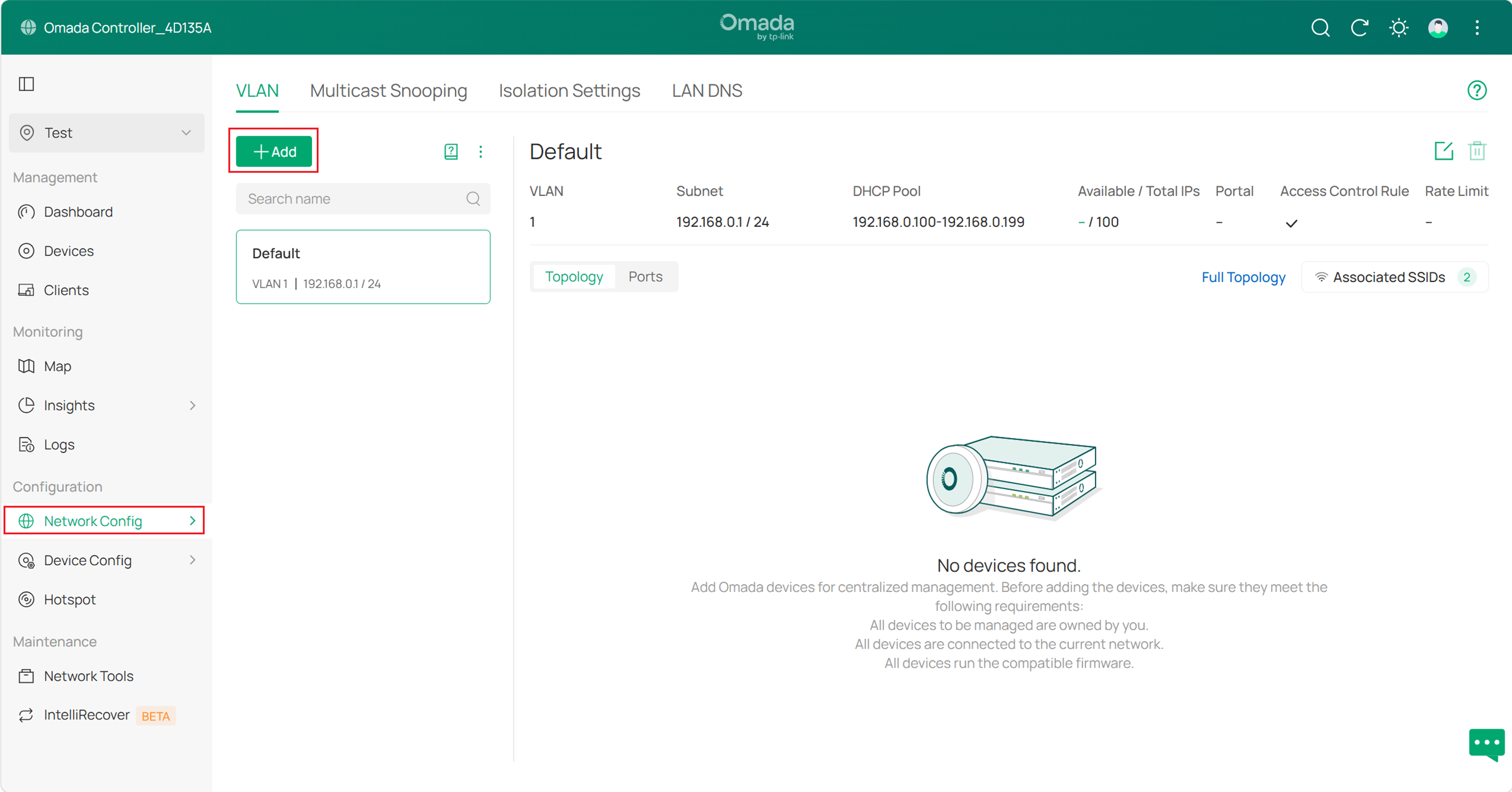
Log in Omada Controller. Go to Network Config > Network Settings > LAN > VLAN, click ‘+Add’ button.
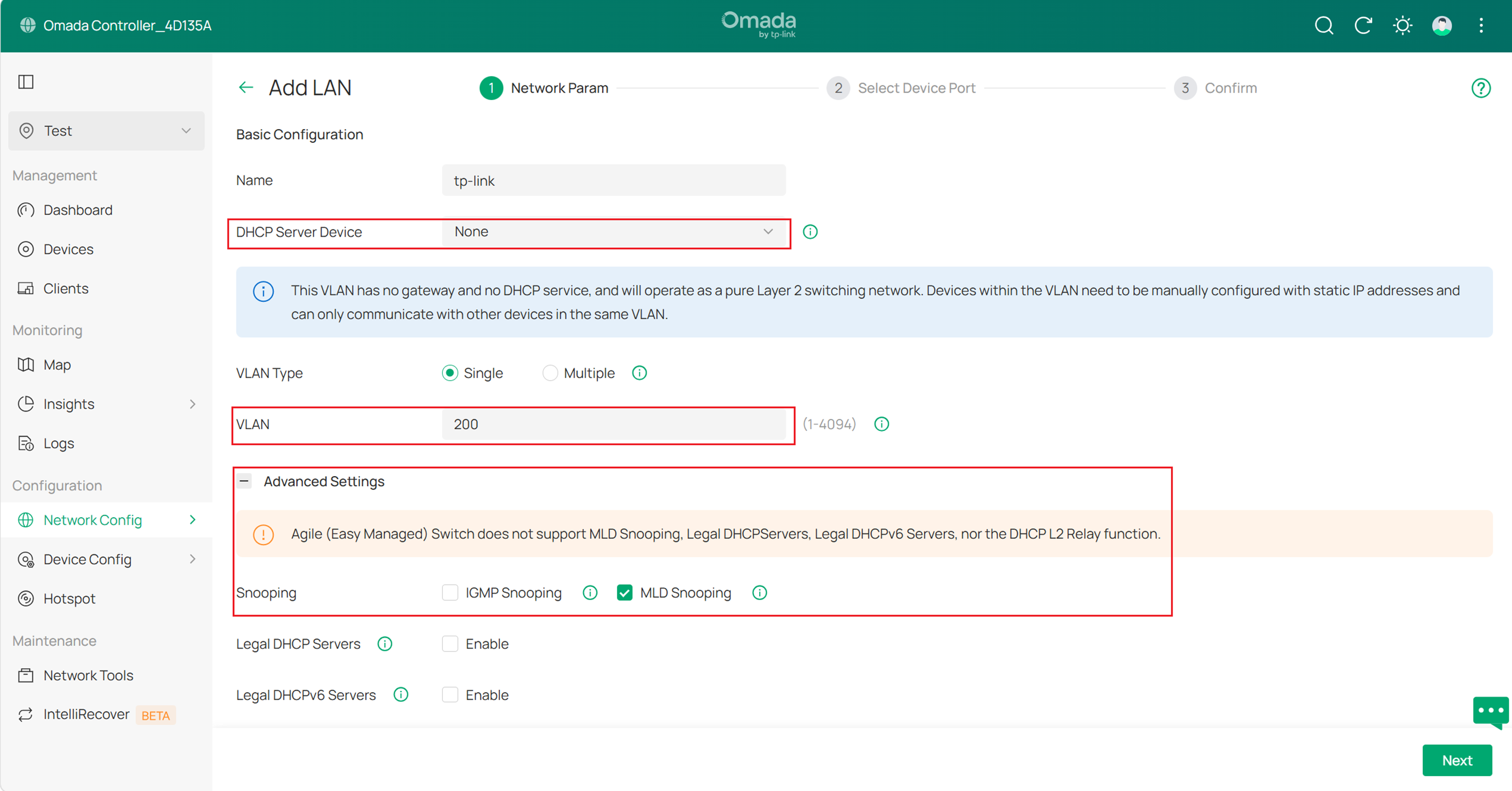
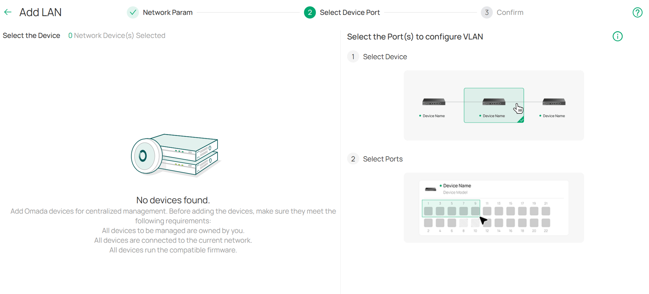
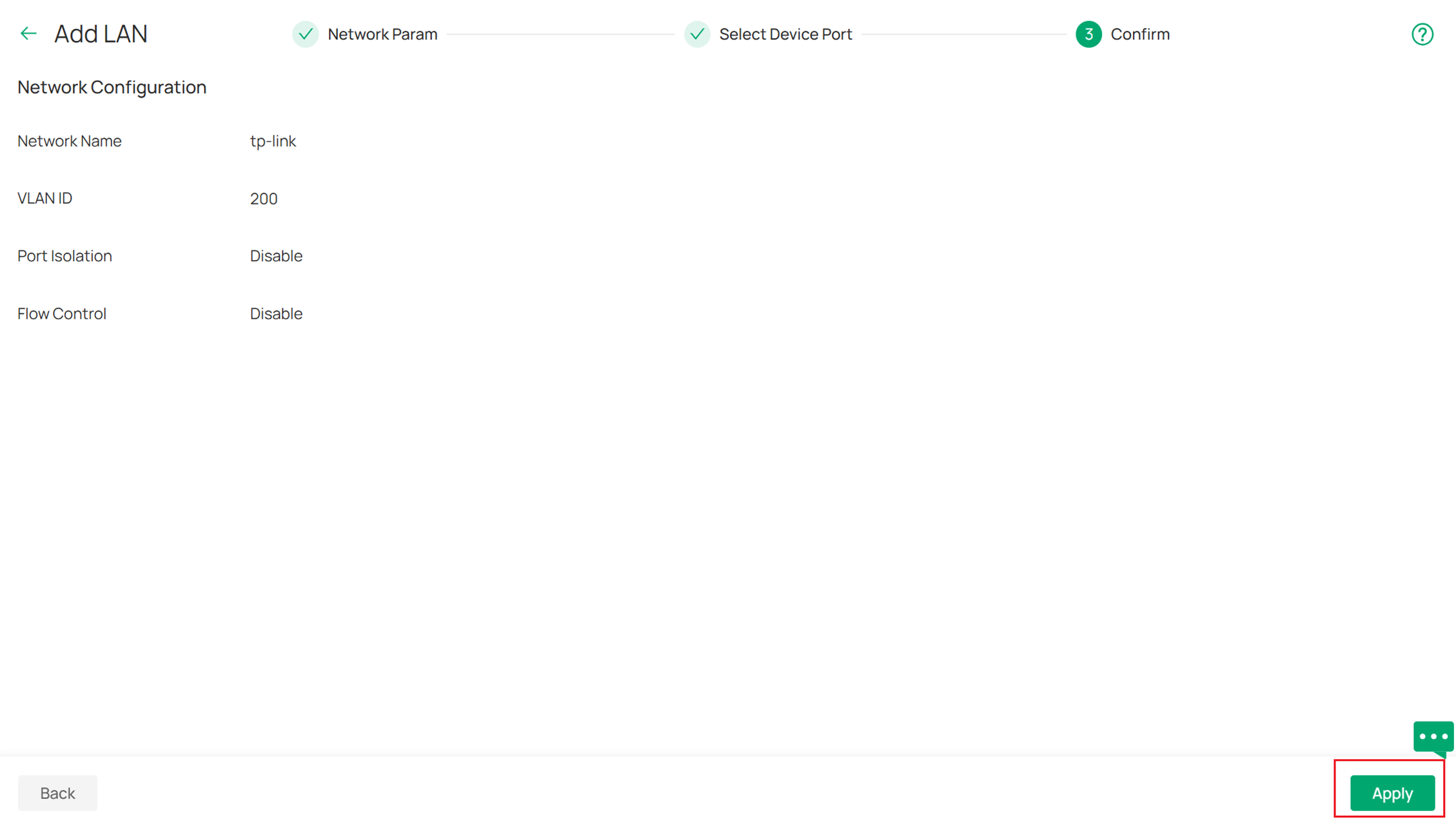
Configure the DHCP Server as None and then tick to enable the MLD Snooping in Advanced Settings. Then select the switches to apply and click Apply to save.
Step 2. Configure the rest parameters through CLI Template.
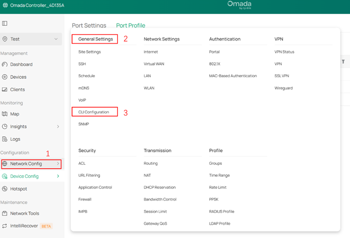
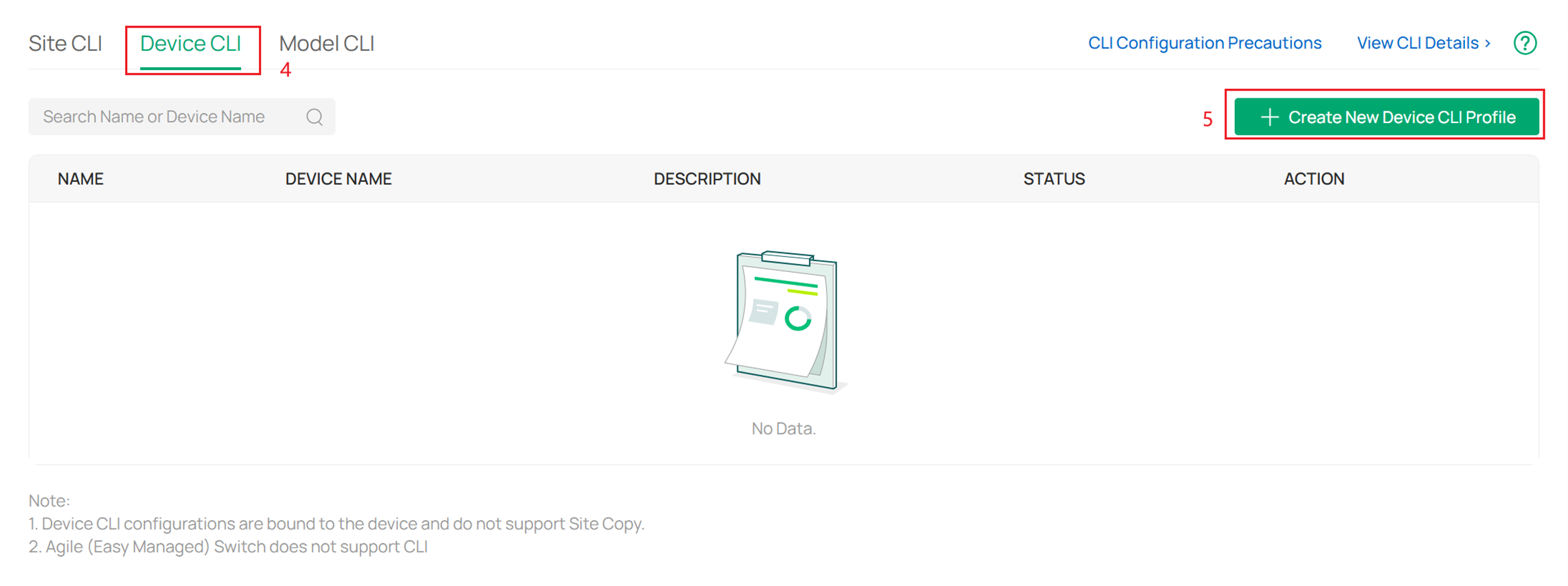
Go to Network Config > General Settings > CLI Configuration > Device CLI, click Create New Device CLI Profile.
Enter a name, description for it and then enter the CLI commands.
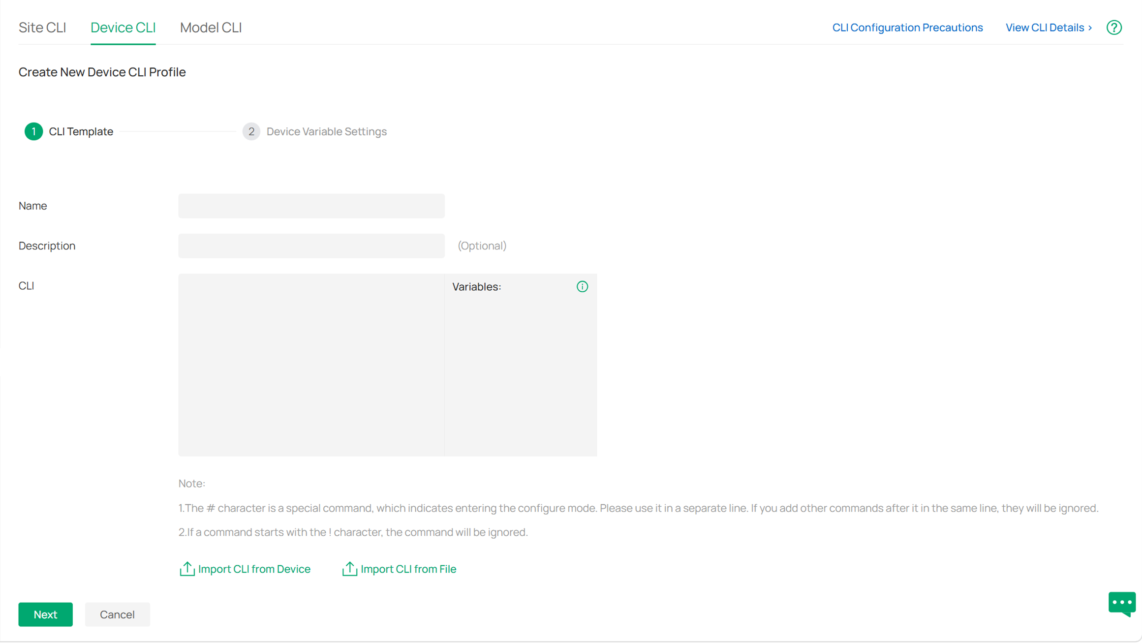
Please note that you can also choose to copy the CLI commands from the other switch configuration files here.
Below is the CLI commands on configuring MLD Snooping with reference to the topology shown in Application Scenario and the principles mentioned earlier (with IPTV VLAN ID=200):
Aggregation Switch:
ipv6 mld snooping drop-unknown
Access Switch to IPTVs:
ipv6 mld snooping drop-unknown
ipv6 mld snooping vlan-config 200 report-suppression
ipv6 mld snooping vlan-config 200 immediate-leave (If all the ports on this switch connect to only one IPTV, if not, don’t use this command and use the below command to enable it by port)
interface gigabitEthernet 1/0/1
ipv6 mld snooping immediate-leave
Access Switch to IPTV Source:
ipv6 mld snooping drop-unknown
ipv6 mld snooping vlan-config 200 querier
For more CLI commands used to configure more parameters, please check the CLI Guide on product’s support page.
Step 3. Apply the Device CLI Profile.
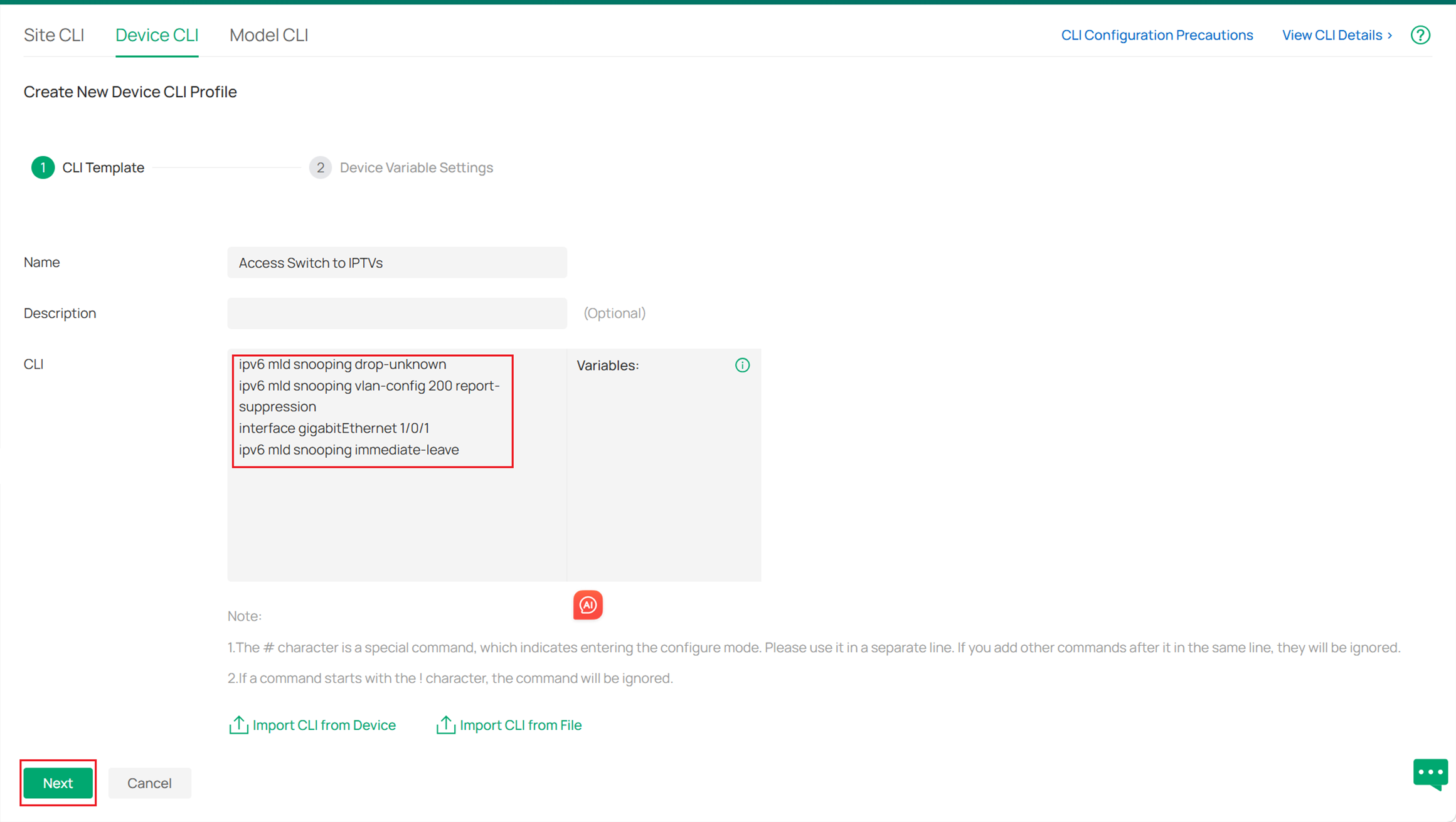
After finishing entering the commands, click Next, and choose the device you want to apply the CLI, here I don’t have any device.
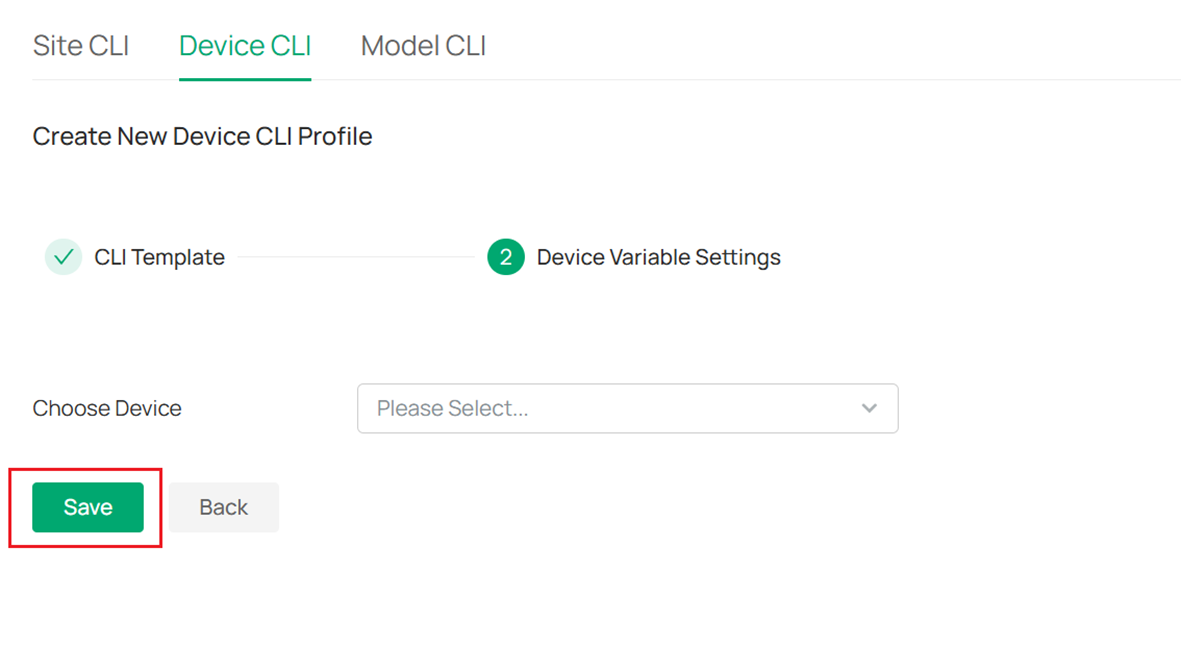
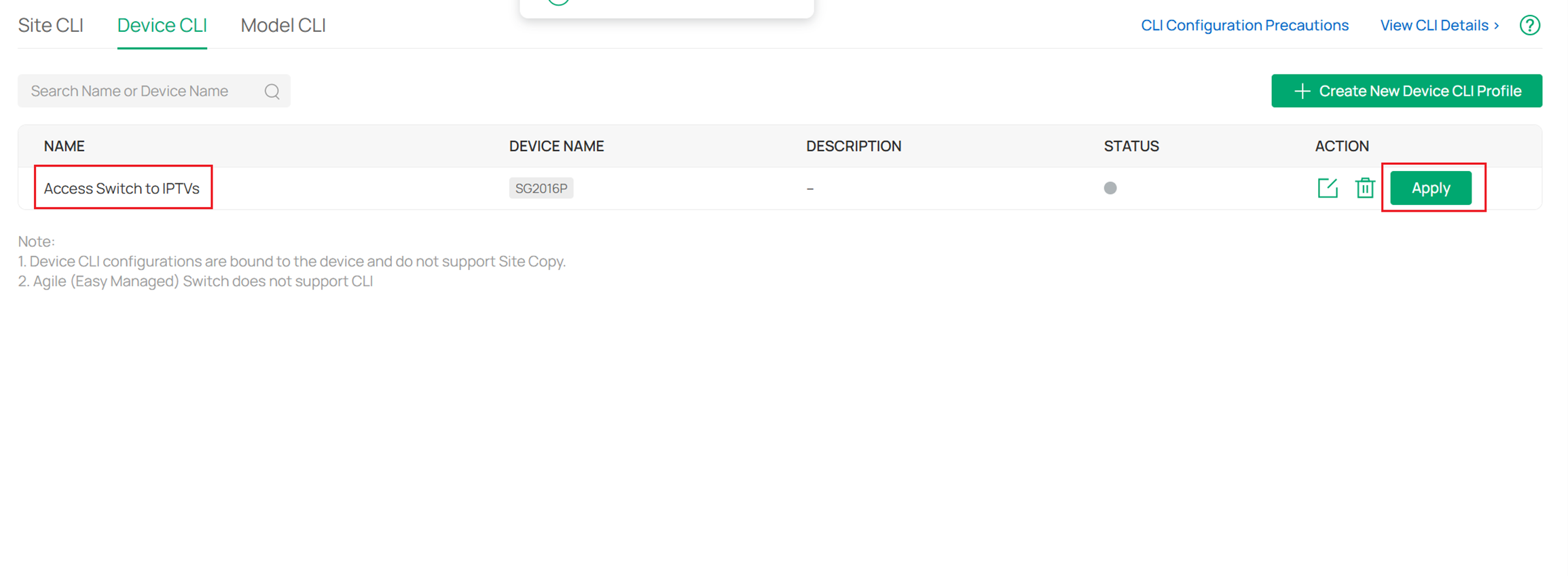
Click Save, and you will see this CLI Template you have just created, click Apply to apply it on the chosen devices.
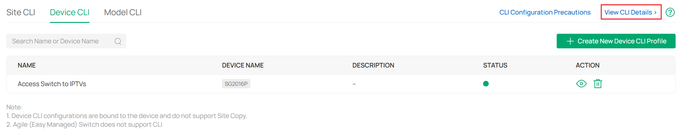
Then you can also check if it has successfully applied by clicking View CLI Details.
For more parameters you can configure, please check the CLI Guide on product’s support page. Also, remember to configure different parameters and features for switches in different positions of your topology following the priciple mentioned earlier.
Configuration on Web UI
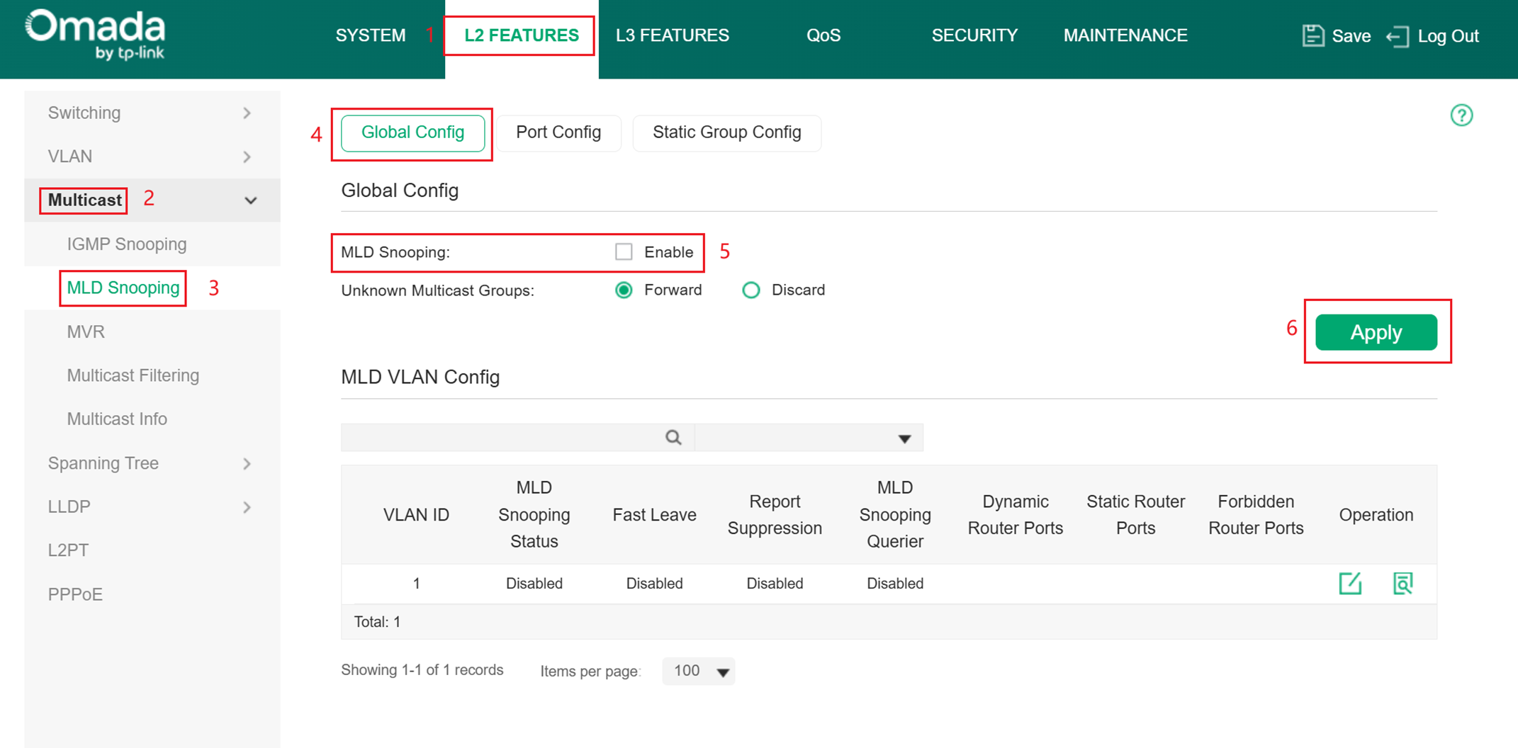
Step 1. Configuring MLD Snooping Globally.
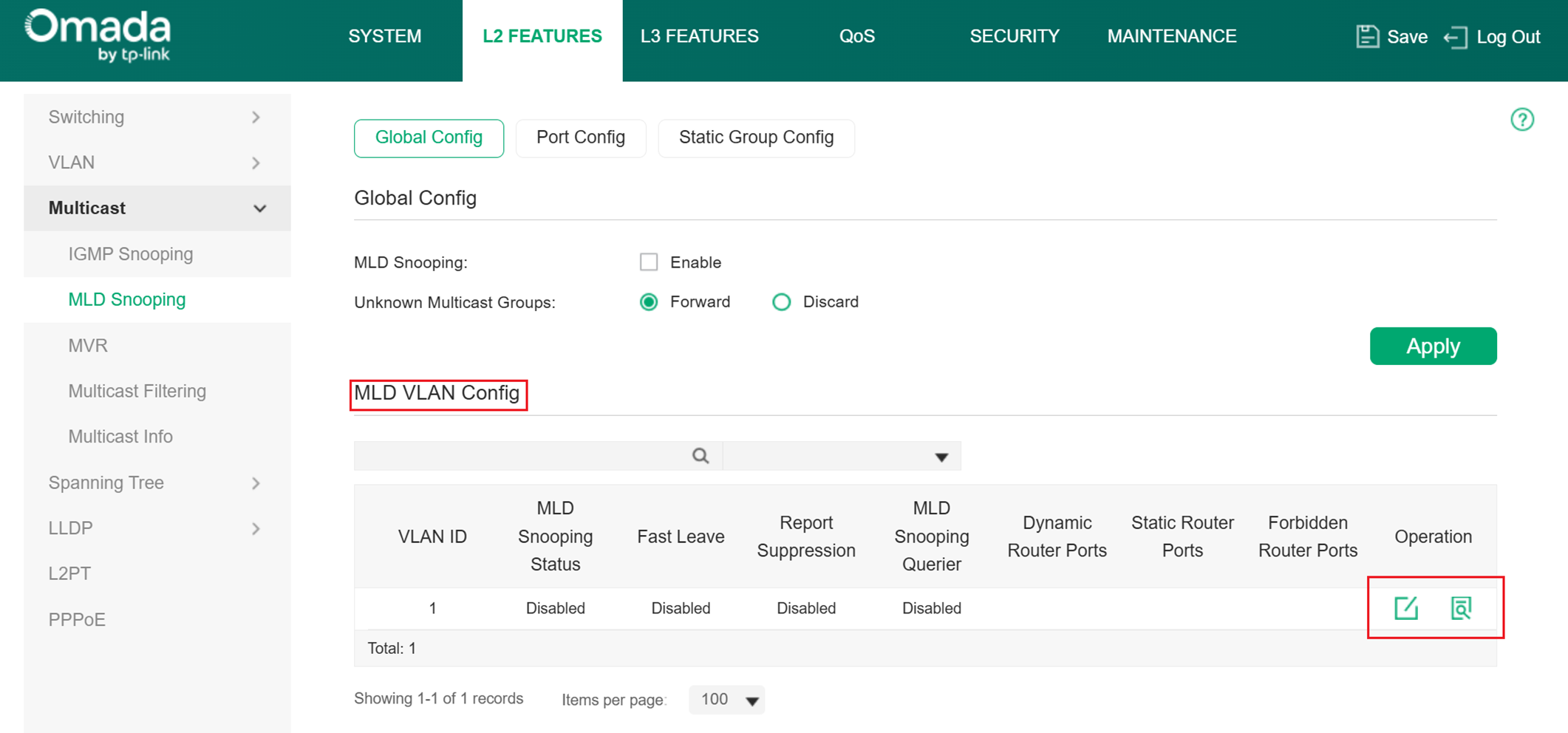
Choose the menu L2 FEATURES > Multicast > MLD Snooping > Global Config to enable the MLD Snooping feature configure the Unknown Multicast Groups feature globally.
Step 2. Configuring MLD Snooping for VLANs.
Before configuring MLD Snooping for VLANs, set up the VLANs that the router ports and the member ports are in. For details, please refer to Configuring 802.1Q VLAN. The switch supports configuring MLD Snooping on a per-VLAN supports configuring Snooping is enabled globally, you also need to enable MLD Snooping and configure the corresponding parameters for the VLANs that the router ports and the member ports are in.
Choose the menu L2 FEATURES > Multicast > MLD Snooping > Global Config > MLD VLAN Config and click in your desired VLAN entry in the MLD VLAN Config section.
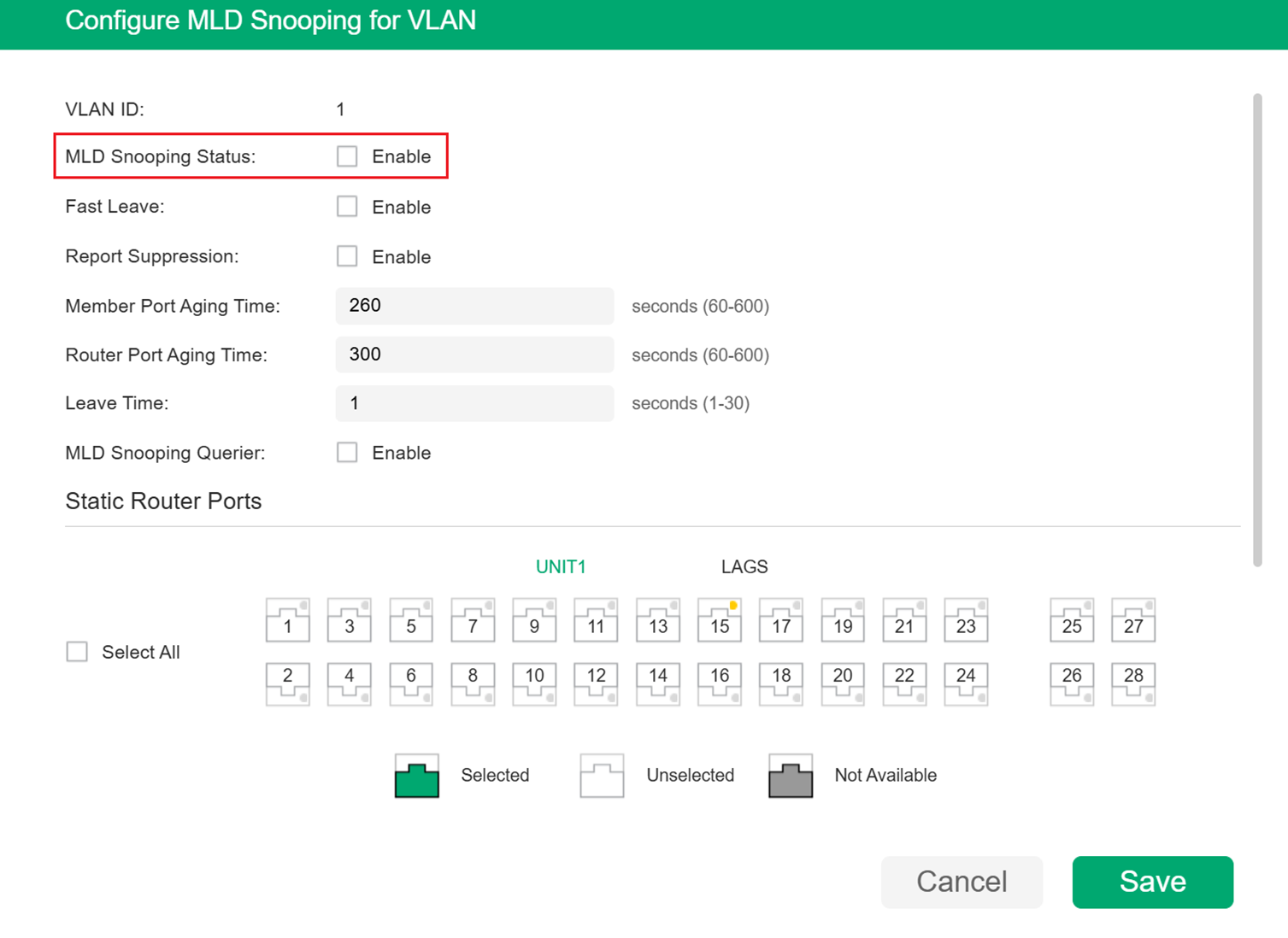
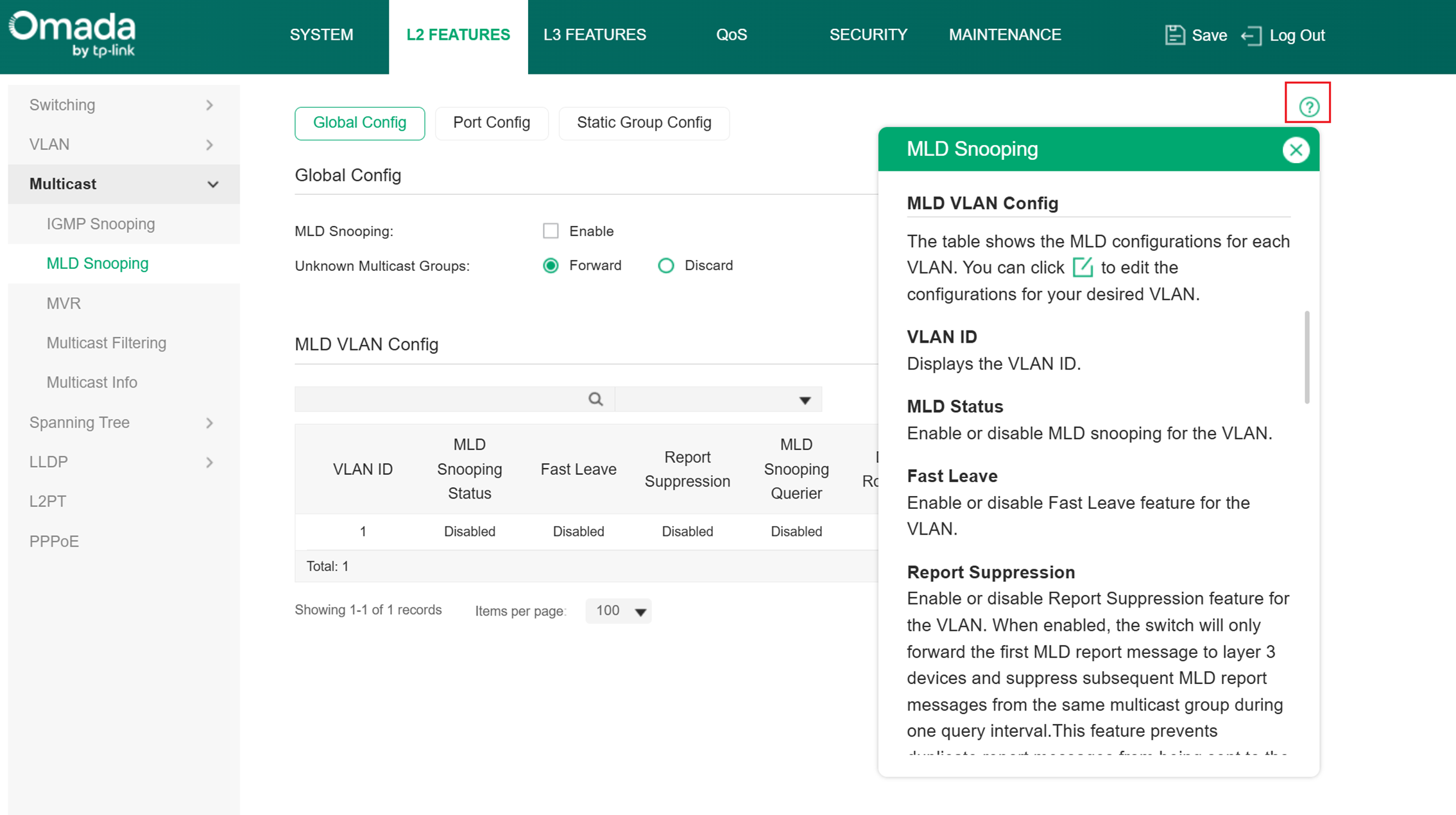
Enable MLD Snooping for the VLAN and configure the corresponding parameters. For the details of other features, please refer to the help center on the config page. After configuring all the features, click Save to save the configurations.
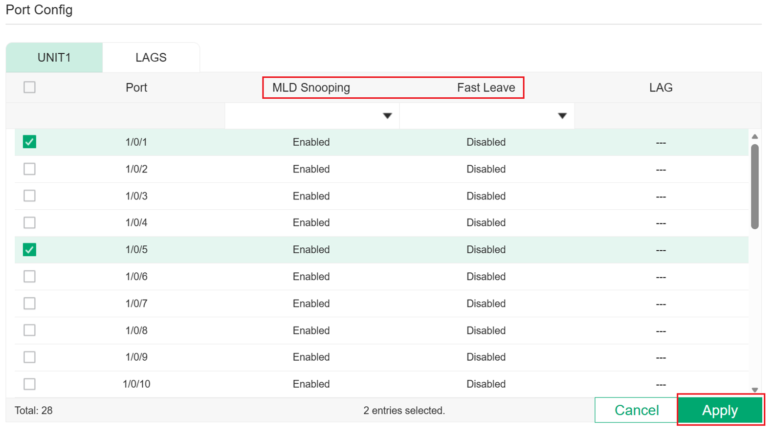
Step 3. Configuring MLD Snooping for Ports.
Go to L2 FEATURES > Multicast > MLD Snooping > Port Config to load the following page.
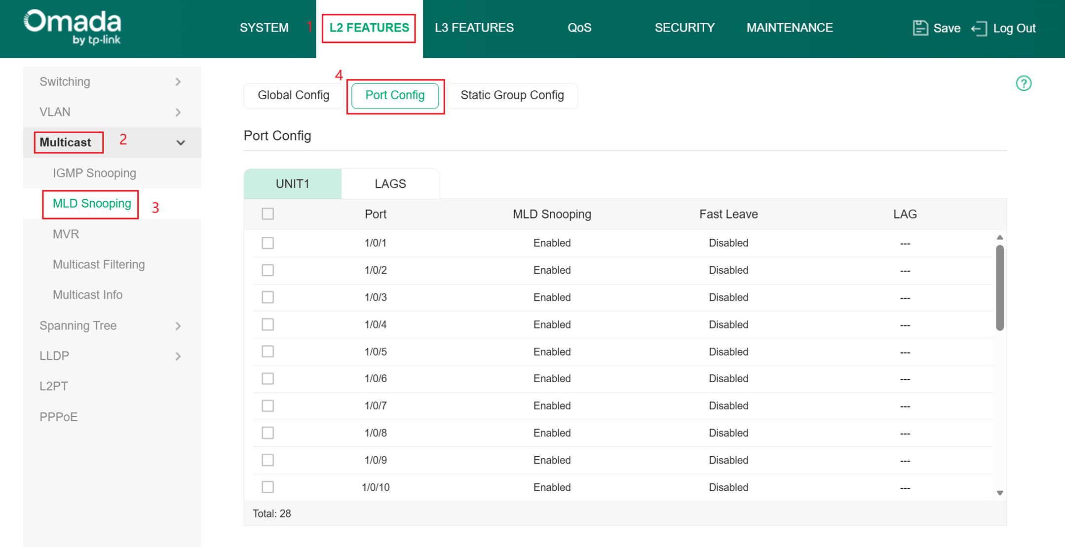
Enable MLD Snooping for the port and enable Fast Leave if there is only one receiver connected to the port.
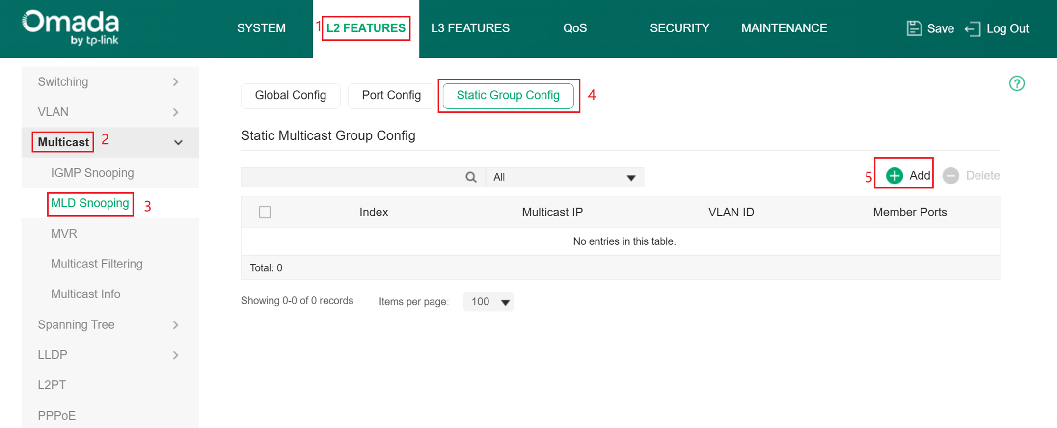
Step 4. Configuring Hosts to Statically Join a Group.
Hosts or Layer 2 ports normally join multicast groups dynamically, but you can also configure hosts to statically join a group.
Go to L2 FEATURES > Multicast > MLD Snooping > Static Group Config and click Add to load the configuration page.
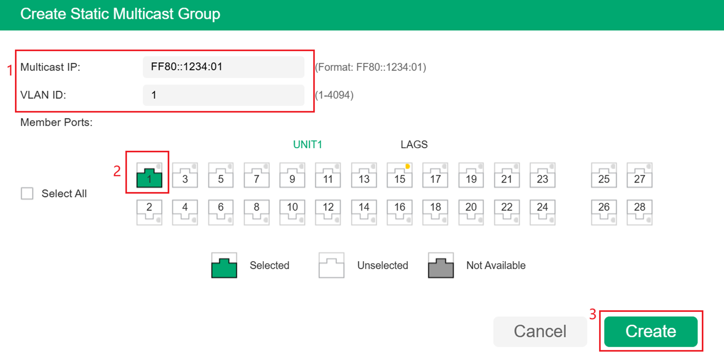
Specify the multicast IP address and VLAN ID. Select the ports to be the static member ports of the multicast group, then click Create to save the configuration.
For more parameters you can configure, please check the CLI Guide on the product’s support page. Also, remember to configure different parameters and features for switches in different positions of your topology following the principle mentioned earlier.
Conclusion
Here we have completed the introduction of configuring MLD Snooping on Omada switches with an example.
Get to know more details of each function and configuration please go to Download Center to download the manual of your product.
