This Article Applies to Omada SDN Controller (V5.1 and later versions)
Introduction
A Wi-Fi heat map is a visual representation of wireless signal coverage and strength.
It aids in pinpointing weak signal areas and enhancing wireless network coverage with simulations during various deployment phases.
The Omada SDN Controller has a built-in Heat Map feature, facilitating better wireless deployment and signal coverage monitoring. You can import a CAD file for automatic wall drawing when generating a heat map.
Procedure
Step 1 Prepare Your CAD File
Contact your layout designer to obtain a CAD file in .dxf format. If you use CAD software to draw the layout yourself, please refer to the relevant CAD software help to export a CAD file in .dxf format.
Step 2 Import Your CAD File to Generate a Map
- Launch your Omada Controller and enter the site view.
- Go to Map > Heat Map. A default map is displayed.

- Click the
 icon behind the Heat Map drop-down list to add a map.

-
- Enter a description for the map.
- Select the general layout of the map. This will make the simulation more accurate.
- Upload your CAD file and click Add. The controller will identify the layout and elements in the CAD file.
Tip: You can drag and drop to move the map, and use the  icons in the upper-right corner to fit/zoom in/zoom out the map. You can also use your mouse wheel to zoom in/out the map.

-
- Click
 to hide undesired layers of the CAD image. Their icons will changed to
  and these hidden layers will not be imported to the map.
 - Click the check box of each desired layer and choose the wall type according to your actual layout. Actual wall settings will make the simulation more accurate. If you are unsure of the wall type, contact your layout designer.
- Click

-
- After setting the wall type for layers, lines in the map will changed accordingly. Click Finish to generate the map.
- Layers with wall type specified will be imported to the map and identified as walls.
- Layers with
 but not specified with wall type will be imported to the map but not identified as walls.
 - Layers with
 will not be imported to the map.
- After setting the wall type for layers, lines in the map will changed accordingly. Click Finish to generate the map.

-
- Set the map scale. Draw a line on the map by clicking and dragging, and then define the distance of the line according to your actual layout.

Now the map is generated from your CAD file.
Tips:
-
-
- After setting the map scale, you can click the
 icon to draw a line on the map to measure the actual distance according to the map scale.
 - If you want to change the map scale, click the
 icon in the upper-right corner.
- After setting the map scale, you can click the
-

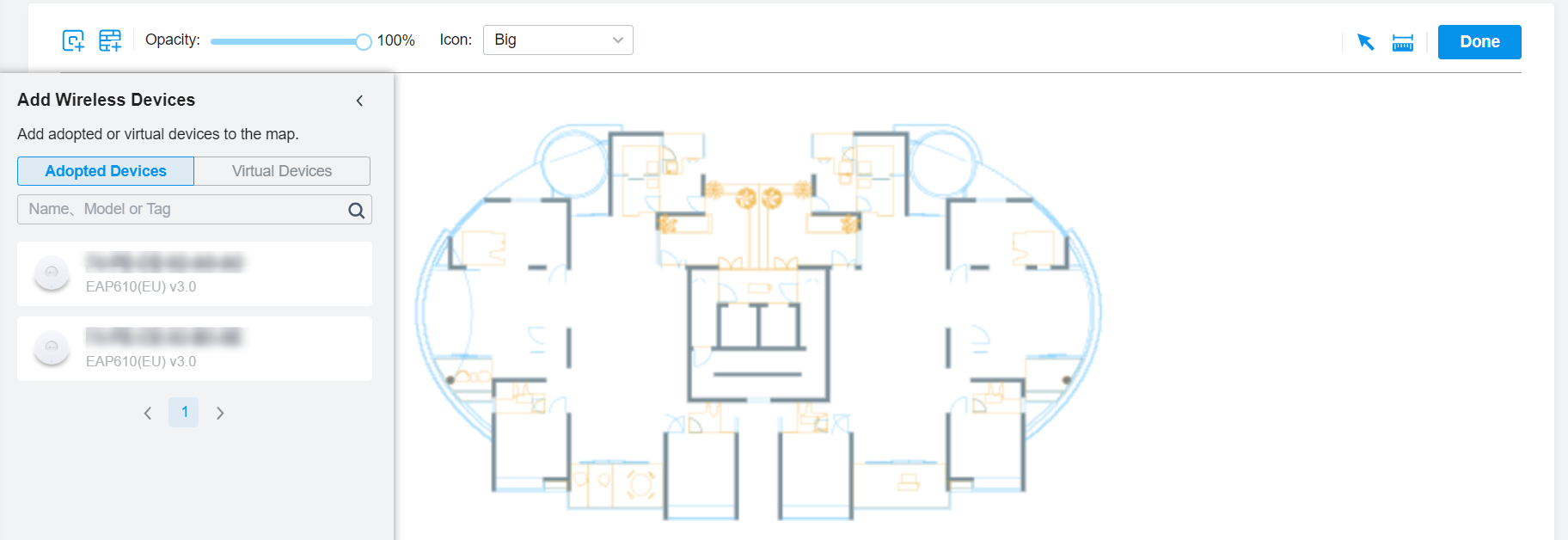
Step 3 Add Wireless Devices to the Map
- Click the
 icon in the upper-left corner. The list of adopted and virtual wireless devices will appear.

- Drag wireless devices to the desired place on the map, and click each device to configure map settings.
- If you add adopted devices, the controller will generate the heat map based on the actual state of the corresponding devices.
- If you add virtual devices, the controller will generate the heat map based on your settings.
Tips:
- You can use the search bar to quickly find the models or device types you want.
- For a virtual device, you can click Copy to Map to quickly copy it to the map.

- Adjust the opacity and icon size if needed. Then click Done.

Step 4 Simulate the Heat Map
Click Simulate to generate the heat map. You can switch each wireless band for heat map simulations. This may take some time, depending on your computer performance and the heat map scale.

Adjust the receiver sensitivity according to the wireless coverage required by the project, then the places that are not filled with “wireless signal” are the places where the wireless coverage does not meet the requirements, you can add or remove wireless devices or adjust device parameters according to the project requirements.
Click the  button to draw the area you want to evaluate, and click Start Calculation to view the signal coverage.

Step 5 Export the Heat Map Report
Click the  icon in the upper-right corner to generate a report, which includes information on the devices, layout, and heat map for the wireless bands you have simulated.


