


Como utilizar backup de link e roteamento baseado em políticas para manter dispositivos críticos online e economizar dados


Conteúdo
Configuração para o Modo Controller para Permitir Determinadas Redes Através da WAN de Backup
Configuração no Modo Controller para Permitir Endereços IP Específicos Através da WAN de Backup
Introdução
Em ambientes de WAN dupla (dual-WAN) onde uma conexão WAN é designada como link de backup, muitas vezes é necessário controlar quais dispositivos e redes têm permissão para usar a conexão de backup durante um evento de failover. Este guia demonstra como usar Roteamento Baseado em Políticas (Policy Routing) para permitir que apenas dispositivos, redes ou endereços IP específicos roteiem tráfego através da WAN de backup.
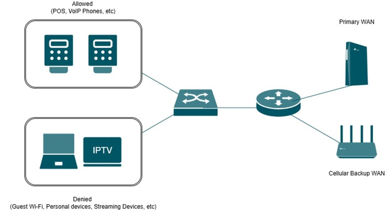
Por exemplo, em um ambiente de cafeteria, sistemas críticos como terminais POS podem ser priorizados para manter o processamento de pagamentos e operações comerciais, enquanto o tráfego não essencial, como o Wi-Fi de convidados, continua impedido de usar a WAN de backup. Essa abordagem ajuda a preservar o uso de largura de banda na conexão secundária, garantindo que os serviços essenciais permaneçam operacionais durante uma interrupção.
Requisitos
- Omada Gateway
Configuração
Este guia demonstra dois métodos comuns para permitir que apenas determinadas redes e dispositivos utilizem a WAN de backup através do Roteamento Baseado em Políticas (Policy Routing).
O primeiro cenário se aplica a ambientes onde os dispositivos são separados em diferentes VLANs ou sub-redes, permitindo que redes específicas sejam roteadas através da WAN de backup durante um evento de failover.
O segundo cenário se aplica a ambientes onde os dispositivos residem dentro da mesma sub-rede, exigindo o uso de Grupos de IP (IP Groups) para permitir seletivamente hosts ou dispositivos específicos através da WAN de backup.
Ambos os métodos fornecem maior controle sobre a utilização da WAN, garantindo ao mesmo tempo que dispositivos críticos mantenham conectividade durante uma interrupção.
Nota: Neste guia, a porta 2.5G WAN1 é a WAN Primária, e WAN/LAN3 é a WAN de Backup
Configuração para o Modo Controller para Permitir Determinadas Redes Através da WAN de Backup
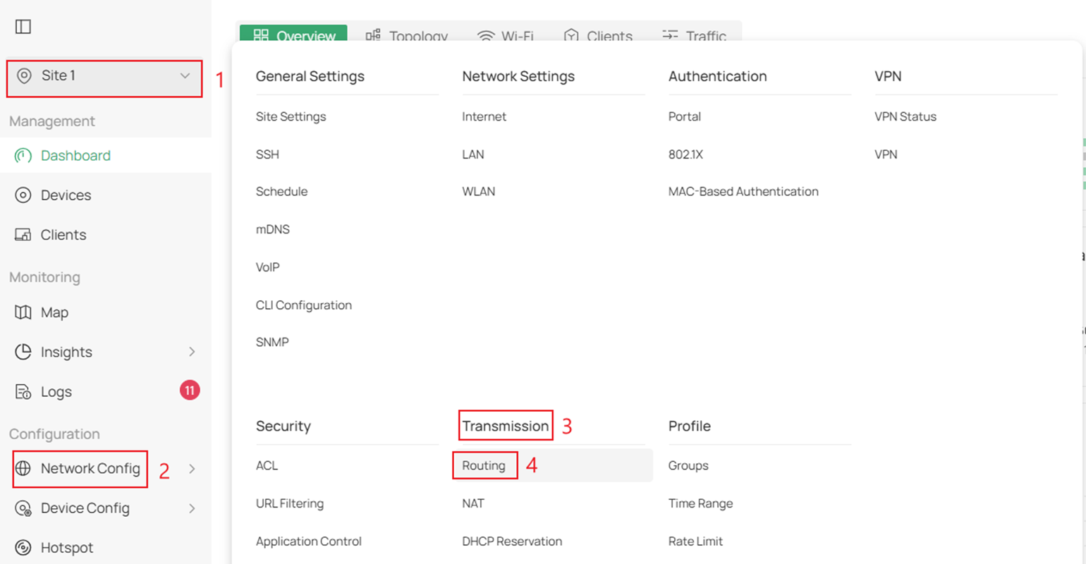
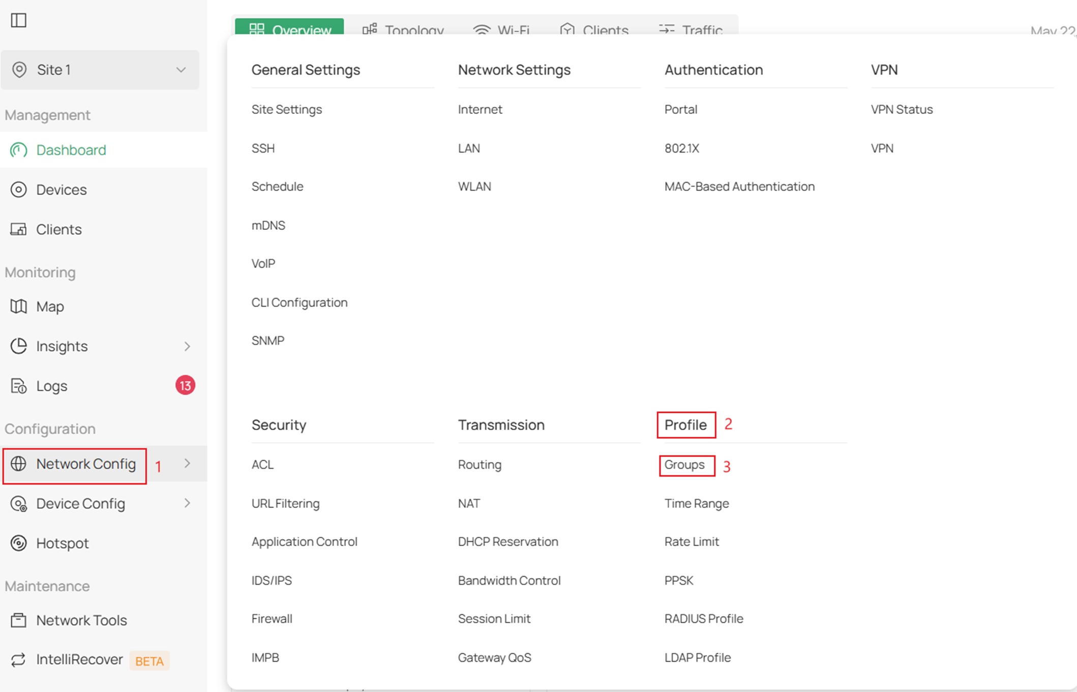
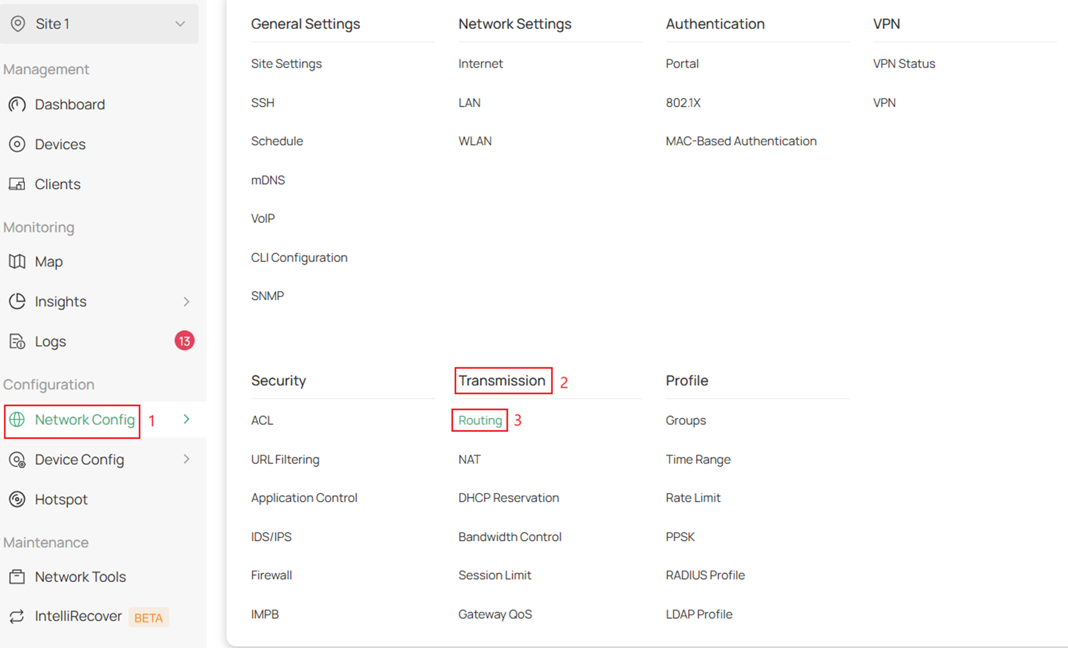
Passo 1. Faça login no seu controller e navegue até Site > Network Config (Configuração de Rede) > Transmission (Transmissão) > Routing (Roteamento).
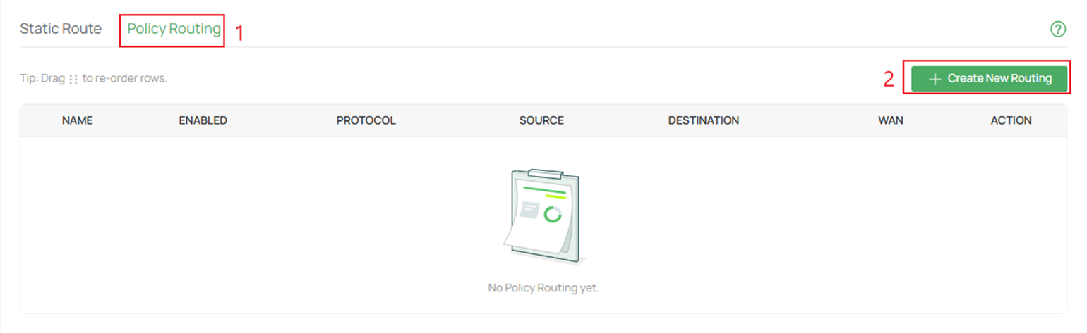
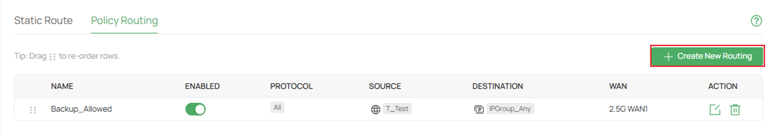
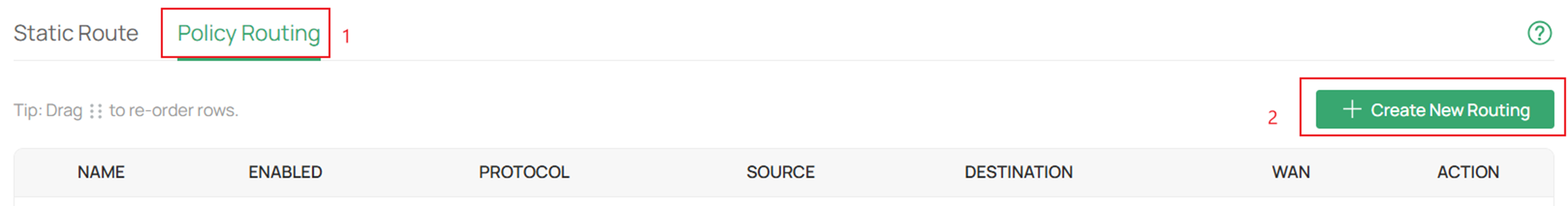
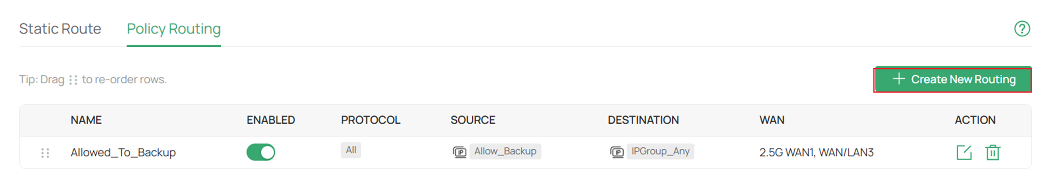
Passo 2. Vá até Policy Routing (Roteamento de Política) e clique em Create New Routing (Criar Novo Roteamento).
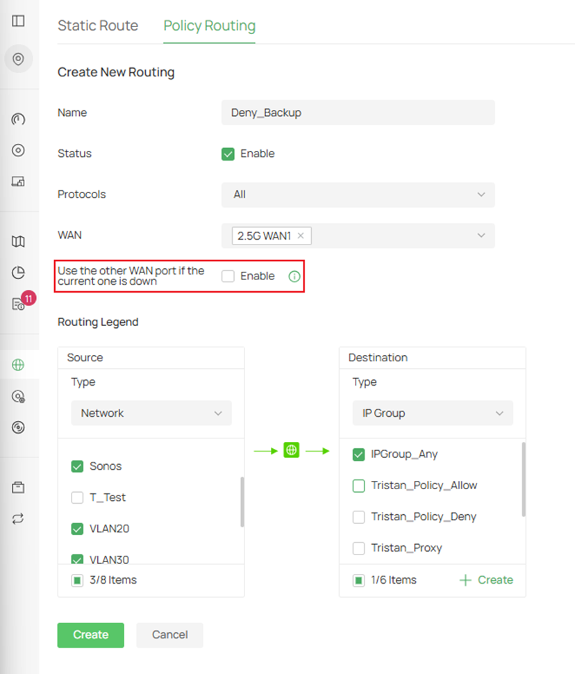
Passo 3. Crie a regra de permissão (Allow Rule).
Preencha os parâmetros para a rede com permissão para passar através da WAN de backup quando a WAN primária cair.
Certifique-se de habilitar a opção Use the other WAN port if the current one is down (Usar a outra porta WAN se a atual estiver inativa) para a regra de permissão.
Clique em Create (Criar) quando concluir.
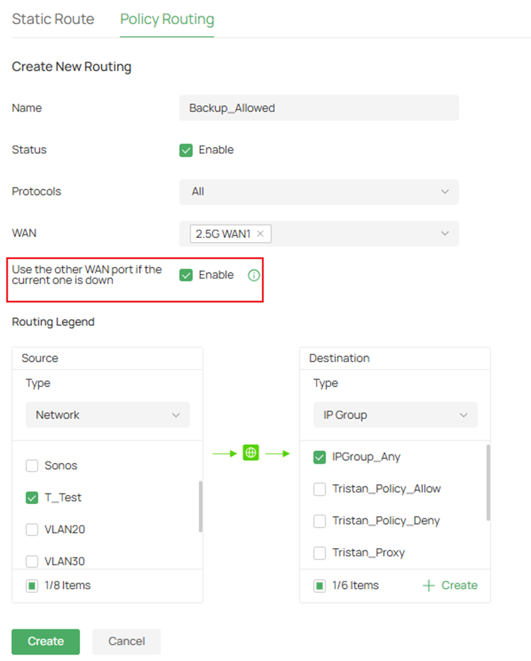
Name (Nome): Insira um nome para identificar a entrada de roteamento de política.
Status: Clique na caixa de seleção para habilitar a entrada de roteamento de política.
Protocols (Protocolos): Selecione os protocolos; a entrada de roteamento de política se aplicará ao tráfego quando este estiver em conformidade com os protocolos selecionados. A entrada só entra em vigor se o tráfego corresponder aos critérios, incluindo os protocolos.
WAN: Selecione a porta WAN Primária, e o tráfego será encaminhado através da porta selecionada. Selecione várias portas WAN para balanceamento de carga, se necessário. As opções de cliente VPN disponíveis são PPTP e L2TP.
Use the other WAN port if the current one is down (Usar a outra porta WAN se a atual estiver inativa): Com esse recurso habilitado, o tráfego será encaminhado através de outra porta WAN quando a porta WAN atual cair.
Routing Legend (Legenda de Roteamento): Especifique a origem e o destino do tráfego aos quais a entrada de roteamento de política se aplica. A entrada só entra em vigor quando o tráfego corresponde aos critérios, incluindo origem e destino.
Network (Rede): Selecione as interfaces de rede para a origem do tráfego.
IP Group (Grupo de IP): Selecione o Grupo de IP para a origem ou destino do tráfego. Você pode criar um novo Grupo de IP nesta página ou ir em Network Config > Profile > Groups para criar um.
IP Port Group (Grupo de Portas IP): Selecione o Grupo de Portas IP para a origem ou destino do tráfego. Você pode criá-lo nesta página ou em Network Config > Profile > Groups.
Location Group (Grupo de Localização): Selecione o Grupo de Localização para o destino do tráfego. Você pode criá-lo nesta página ou em Network Config > Profile > Groups.
Domain Group (Grupo de Domínio): Selecione o Grupo de Domínio para o destino do tráfego. Você pode criá-lo nesta página ou em Network Config > Profile > Groups.
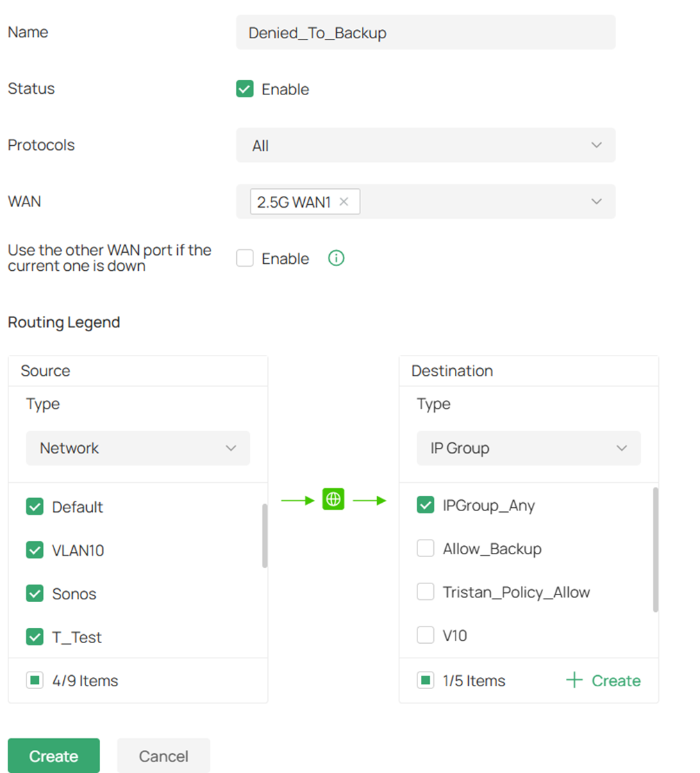
Passo 4. Clique em Create New Routing para criar a regra de negação (Deny Rule).
Passo 5. Preencha os parâmetros adequados para as redes não críticas que não utilizarão a porta WAN de backup quando a primária cair.
Não habilite Use the other WAN port if the current one is down.
Clique em Create quando concluir.
Configuração no Modo Controller para Permitir Endereços IP Específicos Através da WAN de Backup
Passo 1. Ao permitir que determinados hosts utilizem a WAN de backup, você precisará habilitar o Link Backup e criar um IP Group (Grupo de IP).
Siga este artigo para configurar o Link Backup no seu Omada Controller:
How to Configure Link Backup on Omada Gateway via Omada Controller | Omada Network Support
Passo 2. Em seguida, precisamos criar um Grupo de IP para especificar o endereço IP com permissão para trafegar pela WAN de backup.
Navegue até Network Config > Profile > Groups.
Em seguida, clique em Create New Group (Criar Novo Grupo).
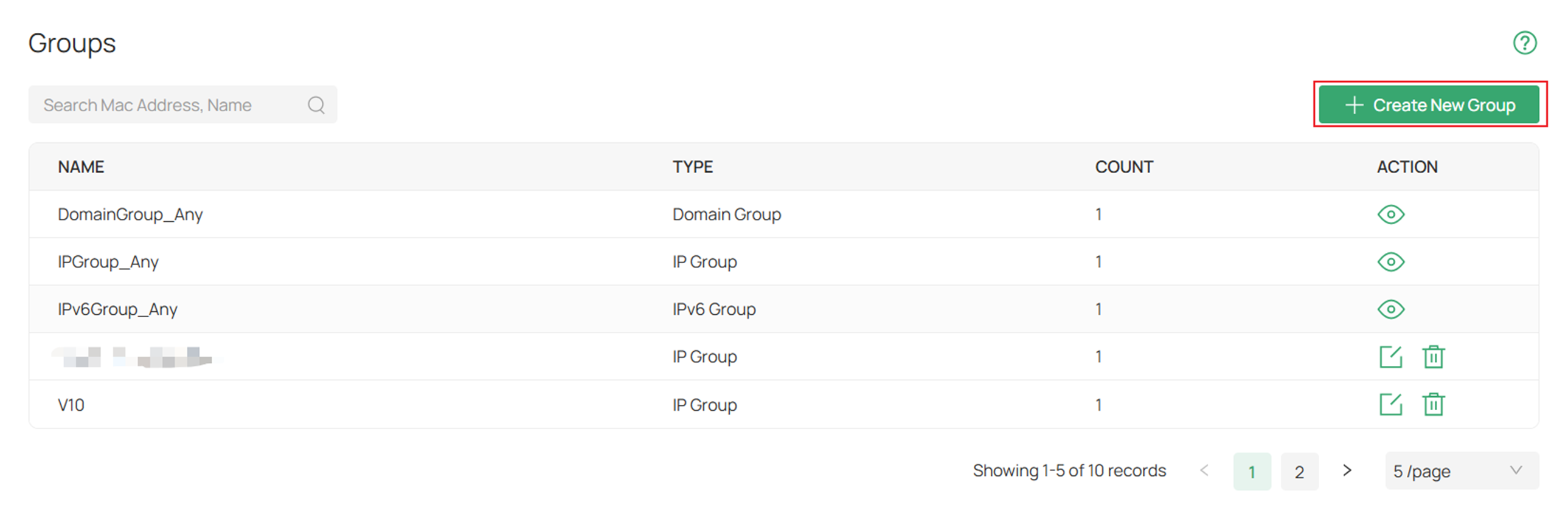
Preencha os parâmetros.
Em IP Subnet, especificamos 2 endereços IP diferentes com uma máscara de sub-rede de 32 bits para permitir apenas esses dispositivos específicos.
Após preencher os parâmetros, clique em Apply (Aplicar).
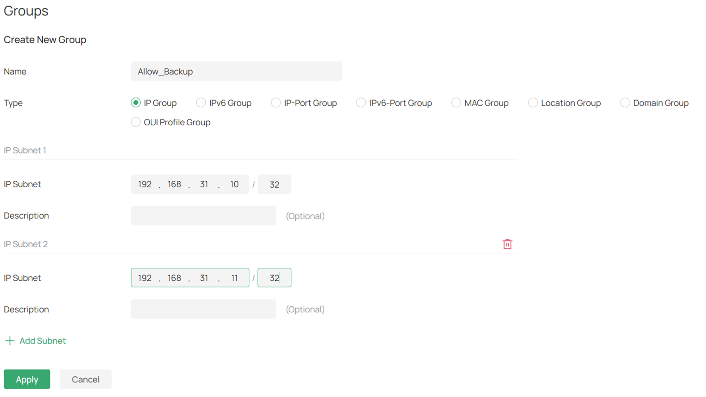
Name (Nome): Insira um nome para identificar o perfil de grupo criado.
Type (Tipo): Selecione o tipo de grupo para o perfil e especifique os parâmetros correspondentes.
IP Subnets (Sub-redes IP): Especifique os endereços IP e as sub-redes do grupo.
Passo 3. Em seguida, crie uma regra de permissão. Navegue até Network Config > Transmission > Routing.
Vá em Policy Routing > Create New Routing.
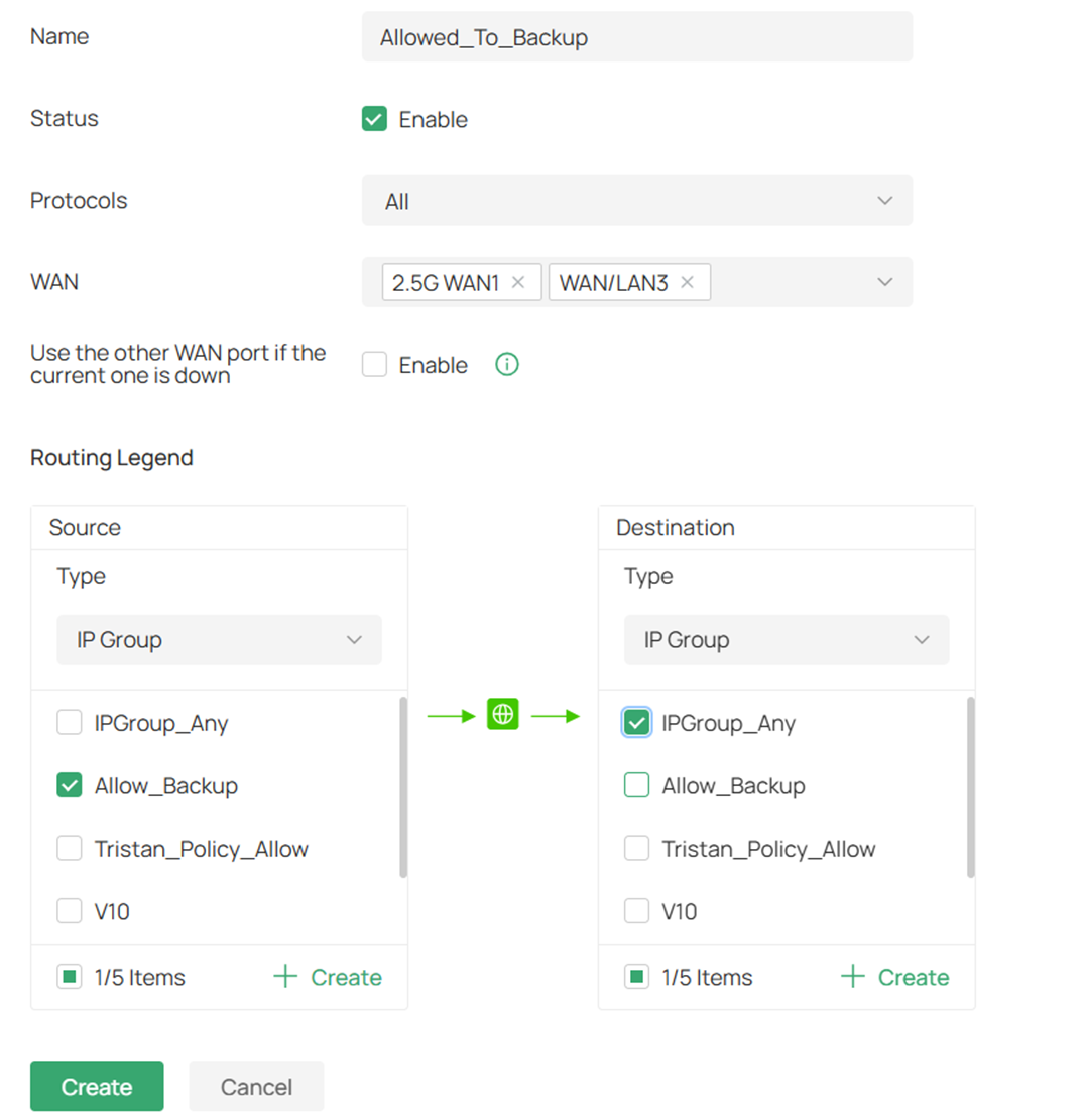
Preencha os parâmetros.
Estes são os parâmetros para os dispositivos com permissão para utilizar a WAN de backup.
Habilitamos ambas as portas WAN e, para o Tipo de Origem (Source Type), selecionamos IP Group.
Clique em Create quando terminar.
Passo 4. Clique em Create New Routing para criar a rota da política de roteamento negada.
Crie o roteamento para a regra negada.
Preencha os parâmetros para as redes ou grupos de IP negados.
Nesta configuração de negação, apenas a WAN primária é especificada e o Source Type (Tipo de Origem) é Network com as redes selecionadas.
Clique em Create ao concluir.
Configuração no Modo Standalone para Permitir Redes e Endereços IP Específicos Através da WAN de Backup
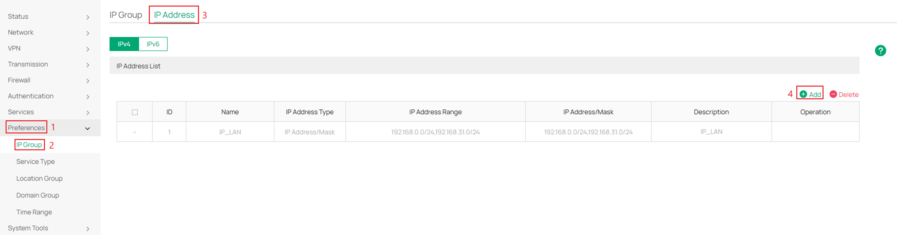
Passo 1. Crie o grupo de IP para a sub-rede ou endereço específico.
Após fazer login na interface local do roteador, navegue até Preferences (Preferências) > IP Group > IP Address > e clique em Add (Adicionar).
Passo 2. Aqui, especifique os endereços IP que participarão da política.
Neste exemplo, os endereços IP permitidos e negados estão na mesma sub-rede.
Se a regra rotear redes diferentes, escolha a opção IP Address/Mask para cada LAN.
Clique em OK quando concluir.
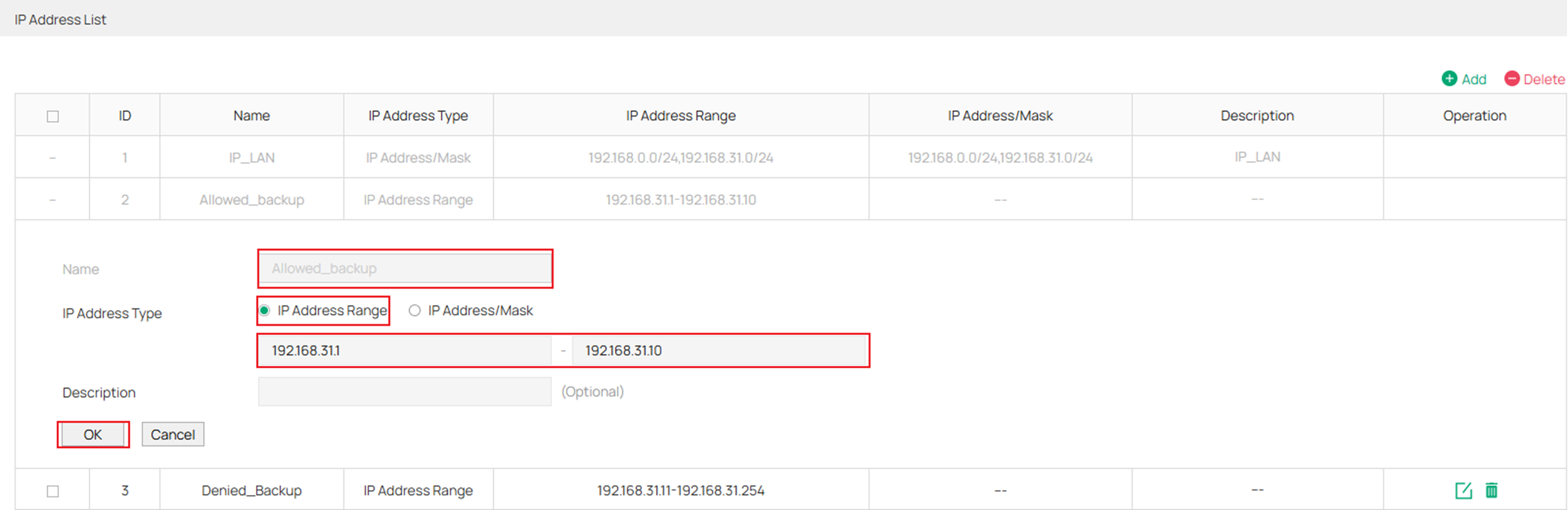
Name (Nome): Insira o nome da entrada de endereço IP.
IP Address Type (Tipo de Endereço IP):
IP Address: Range (Intervalo de IPs): Especifique um endereço IP inicial e um endereço IP final. A regra que referenciar esta entrada será aplicada aos IPs dentro do intervalo.
IP Address/Mask (Endereço IP/Máscara): Especifique um endereço de rede e uma máscara de sub-rede. A regra será aplicada aos IPs contidos nessa faixa.
Description (Descrição): Insira uma breve descrição para facilitar o gerenciamento (máximo de 50 caracteres).
Passo 3. Vá em IP Group, clique em Add e preencha os parâmetros.
O exemplo abaixo mostra um grupo para Allowed_backup. Após concluir este grupo, crie outro grupo para os endereços IP negados especificados no passo anterior.
No total, deve haver dois grupos de IP.
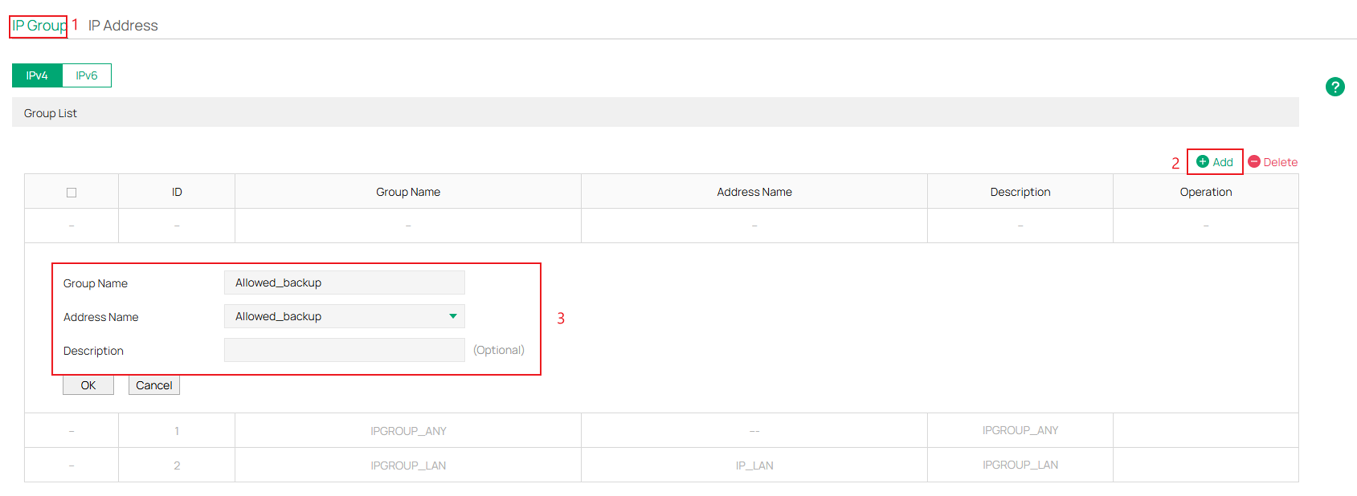
Group Name (Nome do Grupo): Insira o nome do grupo de IP.
Address Name (Nome do Endereço): Selecione a entrada de endereço IP (você pode selecionar mais de uma para o mesmo grupo).
Description (Descrição): Insira uma breve descrição para o grupo de endereços (máximo de 50 caracteres).
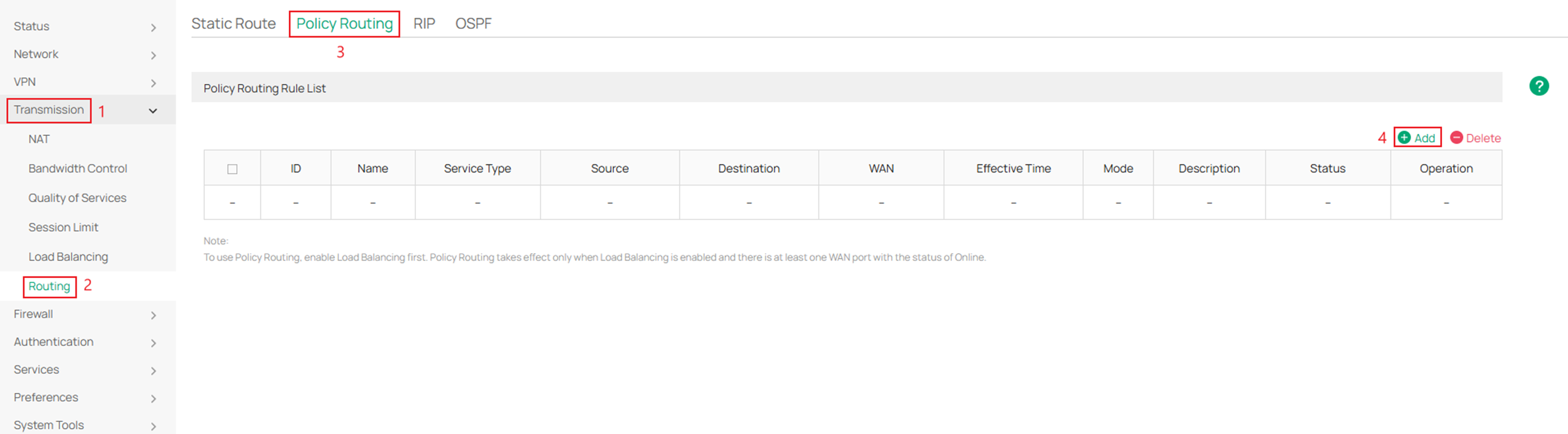
Passo 4: Em seguida, navegue até Transmission > Routing > Policy Routing > e clique em Add.
Passo 5. Preencha os parâmetros para o grupo de IP com permissão para passar pela WAN de backup.
Para o Mode (Modo), certifique-se de escolher Priority (Prioridade) para que, quando a WAN especificada falhar, ocorra a troca para a próxima WAN disponível.
Clique em OK quando concluir.
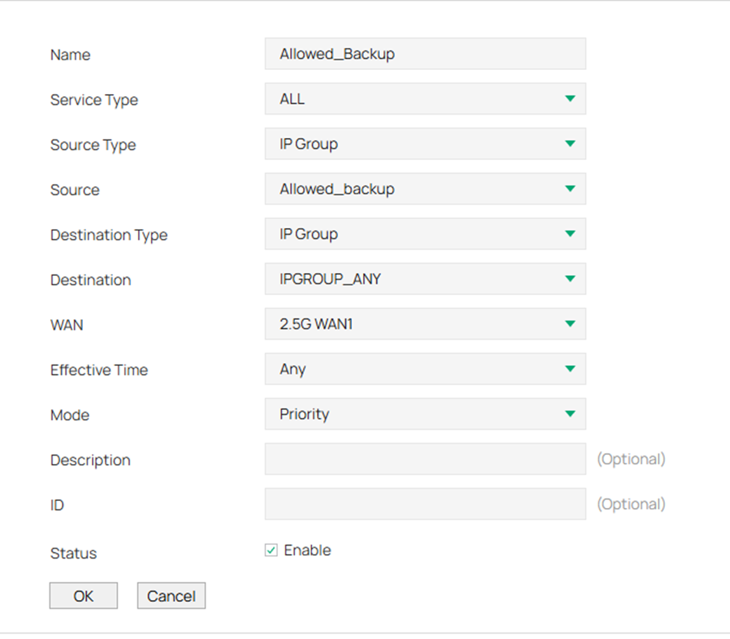
Name (Nome): Insira um nome para identificar a regra de roteamento de política.
Service Type (Tipo de Serviço): Especifique o tipo de serviço para a regra.
Source Type (Tipo de Origem): Apenas IP Group pode ser selecionado. Em seguida, especifique a regra de grupo de IP para a origem.
Source (Origem): Especifique a faixa de IP de origem selecionando os grupos de IP criados.
Destination Type (Tipo de Destino): Você pode selecionar IP Group, Location Group ou Domain Group.
Destination (Destino):
Select IP Group (Selecionar Grupo de IP): Na lista suspensa, selecione um Grupo de IP criado em Preferences > IP Group.
Select Location Group (Selecionar Grupo de Localização): Selecione um ou múltiplos Grupos de Localização criados em Preferences > Location Group.
Select Domain Group (Selecionar Grupo de Domínio): Selecione um ou múltiplos Grupos de Domínio criados em Preferences > Domain Group.
WAN: Selecione a porta WAN para o encaminhamento do tráfego. Selecione várias portas WAN para balanceamento de carga, se necessário.
Effective Time (Tempo Efetivo): Especifique o horário de vigência da regra, criado em Preferences > Time Range.
Mode (Modo): Especifique o modo de roteamento de política para a regra.
Priority (Prioridade): No modo de prioridade, a regra depende do resultado da detecção online. Se qualquer WAN especificada estiver online, a regra entrará em vigor.
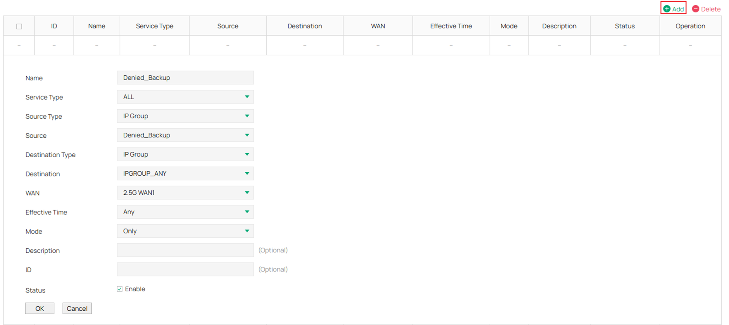
Only (Apenas): No modo "Only", a regra sempre entra em vigor, independentemente do status da porta WAN.
Description (Descrição): Insira uma breve descrição para a regra.
ID: Atribua um número para reordenar a lista (números menores indicam maior prioridade).
Status: Marque a caixa para habilitar a entrada de roteamento de política.
Passo 6: Em seguida, crie uma nova rota de política para o grupo de IP negado.
Clique em Add e preencha os parâmetros.
Ao criar a rota para o grupo de IP negado, certifique-se de que o Mode esteja definido como Only.
Clique em OK quando concluir.
Verificação
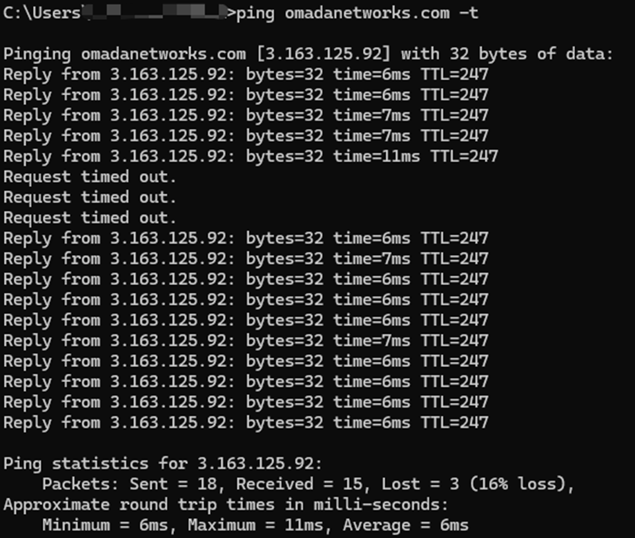
A verificação é realizada usando dois dispositivos: um com permissão para utilizar a WAN de backup e outro com acesso negado.
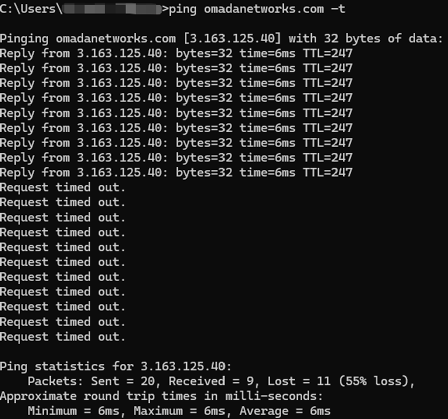
Durante o teste de ping, a mensagem "Request timed out" indica que o dispositivo perde conectividade temporariamente enquanto o processo de failover da WAN ocorre. O dispositivo permitido começará a receber respostas novamente assim que a WAN de backup estiver ativa, enquanto o grupo de IP negado permanecerá em estado de tempo limite (timed-out).
Para o grupo de IP negado, é possível receber brevemente de 3 a 4 respostas bem-sucedidas durante o período de transição. No entanto, assim que a regra de Roteamento de Política for totalmente aplicada e inicializada, o dispositivo retornará ao estado de tempo limite.
Grupo de IP Permitido:
Grupo de IP Negado:
Conclusão
Este guia demonstrou como configurar o failover seletivo de WAN usando Link Backup e Roteamento Baseado em Políticas (Policy Routing). Ao permitir que apenas redes ou dispositivos críticos utilizem a WAN de backup, os administradores podem manter a conectividade essencial enquanto conservam o uso de largura de banda na conexão secundária.
Para conhecer mais detalhes de cada função e configuração, acesse o Centro de Download para baixar o manual do seu produto.
FAQ (Perguntas Frequentes)
Q1: O que devo fazer se minha rota de política não estiver funcionando?
A1: Certifique-se de que o dispositivo que você está testando esteja na sub-rede da regra de roteamento de política configurada.
