


Contents
Introduction
In outdoor scenarios where wired networks are difficult to deploy, you can use the mesh function of EAP to extend the coverage of the wireless network. Currently, the mesh function is only supported on APs managed by a controller. This article mainly introduces how to use the APP to operate the controller and complete mesh networking. Depending on the type of controller you are using, the following requirements apply:
- If you are using a Cloud-based Controller, the APP only needs to be able to connect to the internet.
- If you are using a Local Controller (software controller or hardware controller) and cloud access is enabled, the APP must meet one of the following conditions: either connect to the internet or connect to a local Wi-Fi network that can communicate with the controller.
- If you are using a Local Controller and cloud access is not enabled, the APP needs to be able to connect to a local Wi-Fi network and communicate with the controller.
For a detailed introduction to the mesh mechanism and usage considerations, you can refer to the following article: https://www.omadanetworks.com/support/faq/4307/.
Requirements
- Omada Controller (Software Controller / Hardware Controller / Cloud-based Controller, v5.9 and above)
- At least two EAPs (using EAP610 and EAP613 as examples)
- Omada APP (using V5.0 as an example)
Configuration
Step 1. Build the topology
First, ensure that one EAP is adopted by the controller (in this article, the EAP610 is used as an example), while the other EAP is only powered on without connecting to an upstream device (in this article, the EAP613 is used as an example). This will cause the EAP613 to enter the isolated state, and you can see that the indicator light of the EAP613 is blinking continuously.
On the APP login page, if your Controller has MSP mode enabled, there will be three views: the MSP view, the customer view, and the site view. If MSP mode is not enabled, only the latter two views will be available.
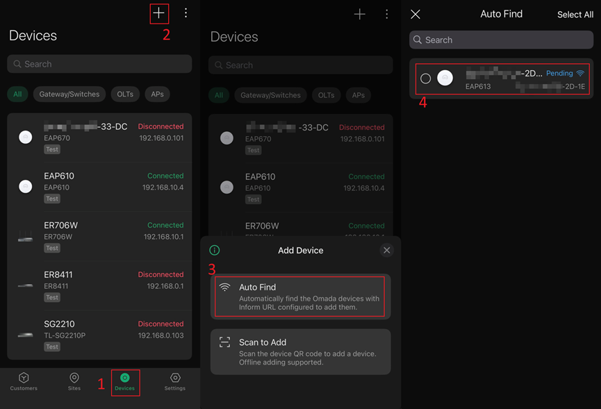
a. In the MSP view, the Devices tab does not automatically display the downstream APs waiting to form a mesh. You need to click the + in the upper right corner to add them manually (using Auto Find as an example here):
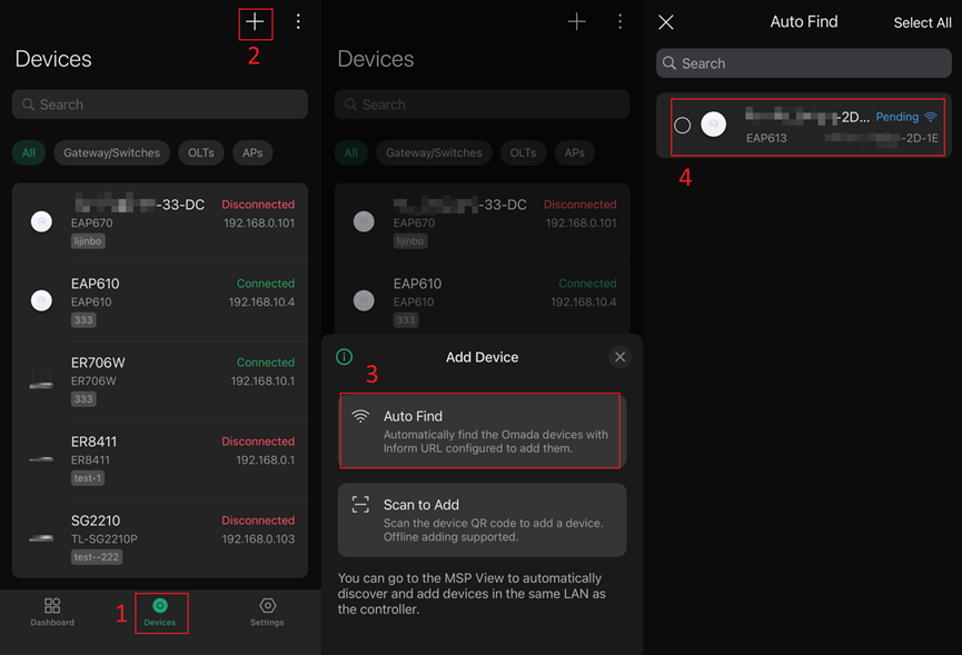
b. In the customer view, the Devices tab does not automatically display the downstream APs waiting to form a mesh. You need to click the + in the upper right corner to add them manually (using Auto Find as an example here):
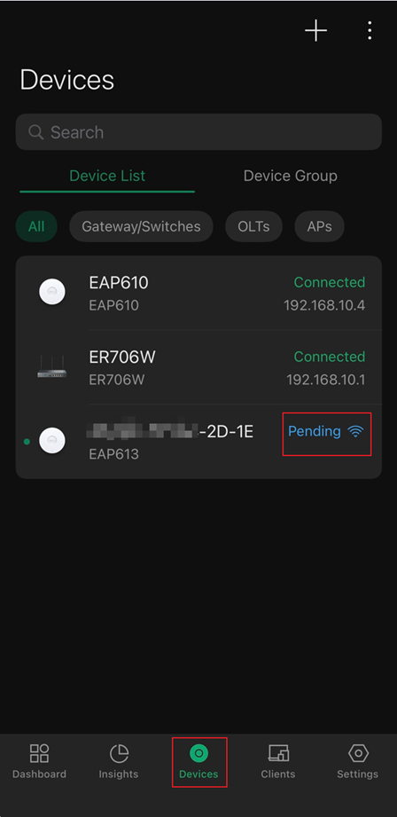
c. In the site view, the Devices tab automatically display the downstream APs waiting to form a mesh. You will see that the EAP610 is displayed as Connected, while the EAP613 is displayed as Pending with a wireless icon.
Step 2. Select the uplink device for the mesh AP
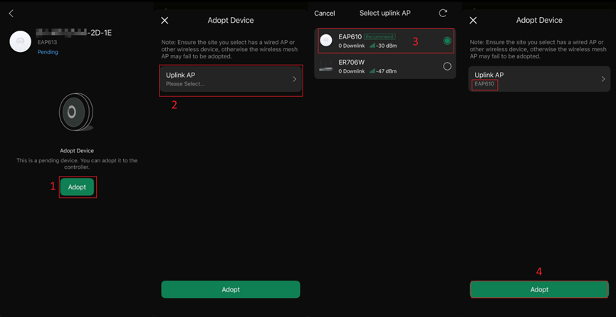
Since the process of forming a mesh is largely the same across the three views, the following steps will use the site view as an example for easier observation and demonstration. Access the private configuration interface of the EAP613, follow the steps sequentially, select EAP610 as the Uplink AP, and click Adopt.
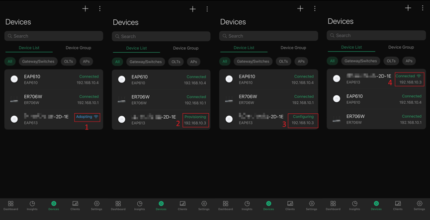
Step 3. Observe the mesh process
On the Devices page of the APP, you can observe that the meshed EAP613 goes through four statuses: Adopting, Provisioning, Configuring, and Connected. This process typically completes within about a minute. Additionally, you may notice a wireless icon next to the Connected status of the EAP613, indicating that it is connected to the controller via mesh.
Step 4. Check the mesh result
Access the private configuration interface of EAP610, click on the Linked Devices section, and you will see EAP613 listed in the Downlinks along with its signal strength.
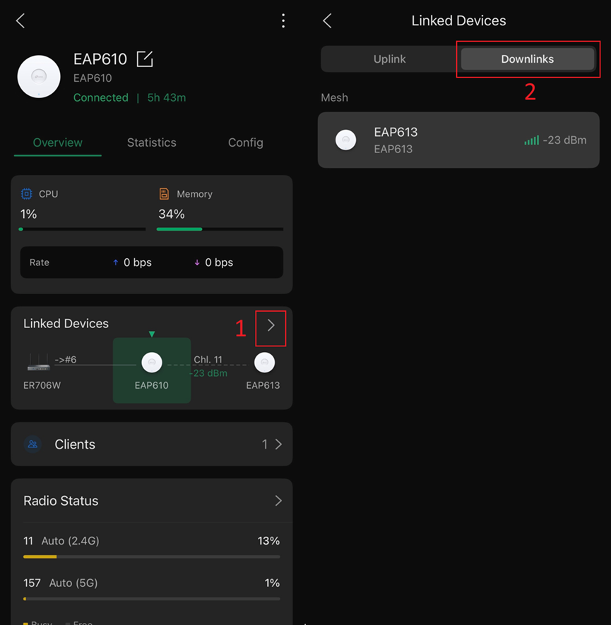
Of course, you can also check the Uplink option in the private configuration interface of EAP613:

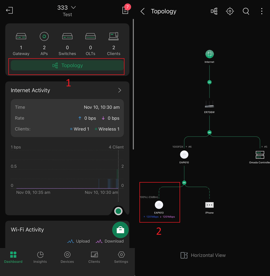
Step 5. View the network topology
You can check the current network topology in the Dashboard tab at the bottom of the APP. There, you will see the two EAPs connected by a dashed line, indicating that the EAP613 is connected to the EAP610 via mesh. Additionally, information such as the mesh connection signal strength and uplink/downlink rates is displayed for the EAP613.
Conclusion
This article provides a detailed step-by-step demonstration of how to configure the mesh function via the APP, allowing you to check the status of the mesh connection upon completion.
Get to know more details of each function and configuration please go to Download Center to download the manual of your product.
QA
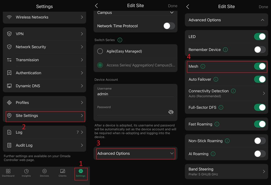
Q1: What should I do if I cannot form a mesh?
A1: Find the Mesh option in Settings > Site Settings > Advanced Options and ensure it is enabled.
Q2: How to troubleshoot if mesh setup fails?
A2: We currently have a detailed troubleshooting guide available. You can refer to the following FAQ: https://www.omadanetworks.com/support/faq/4078/
