


Contents
Introduction
VRF is short for Virtual Routing and Forwarding. By configuring VRF, we could create multiple VRF instances (also known as VPN instances) on a single router or layer 3 switch, each instance will have their own separated routing table, so the same physical device could be split into multiple virtual devices and they could handle IP forwarding independently. This means the entries within different VRF instance routing tables will be completely independent and not related to each other. By creating interfaces and assigning them to different VRF instances, we could use the same IP address and subnet address for different interfaces and networks on the same VRF device. This significantly improves network efficiency and resiliency following the growing demands for campus network.
Currently VRF is only supported on Omada Campus switches (Excluding SG5xxx Switches), and it is limited to a single device, which means the different VRF instances created will only separate the network on this single device, the VRF information will not be transmitted to other connected devices. VRF on Omada Campus switches supports both IPv4 and IPv6 network, this could be configured via IPv4 or IPv6 address family added to a VRF instance after the instance is created.
Requirements
- Omada Campus Switches (Excluding SG5xxx Switches)
- Omada Controller V6.1 and above
Configuration
In the following part, we will give a simple example on how to configure VRF based on this topology:
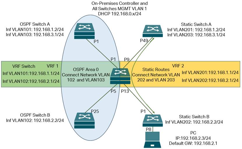
In this network, the On-Premises Controller and all switches will be handling management traffic within default MGMT VLAN 1, with subnet 192.168.0.x/24, this will ensure the management of all switches on controller uninterrupted.
Based on this, we create two VRF instances on the VRF Switch in the middle of the topology, VRF1 and VRF2, create four VLANs with their interfaces: 101, 102, 201, 202, for both VLAN 101 and 201, the IP addresses and subnets are the same: 192.168.1.1/24, for both VLAN 102 and 202, the IP addresses and subnets are the same: 192.168.2.1/24. The interface VLAN 101 and 102 will be joined in VRF1, interface VLAN 201 and 202 will be joined in VRF2, so they could use the same IP address and subnet address on the same switch.
For the two interfaces: interface VLAN 101 and 102 on VRF Switch, they belong to VRF1 and will then connect to OSPF Switch A and OSPF Switch B. By default, there is no route between network VLAN 102 on OSPF Switch B and network VLAN 103 on OSPF Switch A. To solve this, we enable OSPF on OSPF Switch A, OSPF Switch B and the VRF1 of VRF Switch, so the routes between VLAN 101, 102 and 103 networks could be established via OSPF, and we should be able to communicate between the network VLAN 103 on OSPF Switch A and the network VLAN 102 on OSPF Switch B.
For the two interfaces: interface VLAN 201 and 202 on VRF Switch, they belong to VRF2 and will then connect to Static Switch A and Static Switch B. By default, there is no route between network VLAN 202 on Static Switch B and network VLAN 203 on Static Switch A. To solve this, we configure static routes on Static Switch A and the VRF2 of VRF Switch, so the routes between network VLANs 202 and 203 can be established. We then configure port 8 on Static Switch B as an access port of VLAN 202 and connect a PC to it, configure the PC’s IP address as 192.168.2.3/24, which is within network VLAN 202, and set the default gateway as 192.168.2.1, which is the interface of VLAN 202 on VRF2 of VRF Switch. After this, we should be able to communicate between the network VLAN 203 on Static Switch A and the PC.
Basically, what we need to do is to create the VLANs on all devices. On VRF Switch, create the VRF instances, after that, create the interfaces accordingly and assign them to correct VRF instances, then configure the IP addresses for these interfaces. On all other switches, create the interfaces accordingly and configure IP addresses for them. After configuring the port VLAN status on all switches, all interfaces should be up and running. We then enable OSPF and static routes as mentioned above, so the connectivity will be fully established while keeping the topology as two separate parts.
Step 1. Connect the cables as shown in topology, including the controller, by default, the controller and all switches should be within the same default subnet, adopt all the switches.
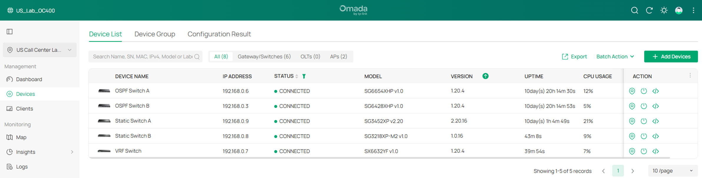
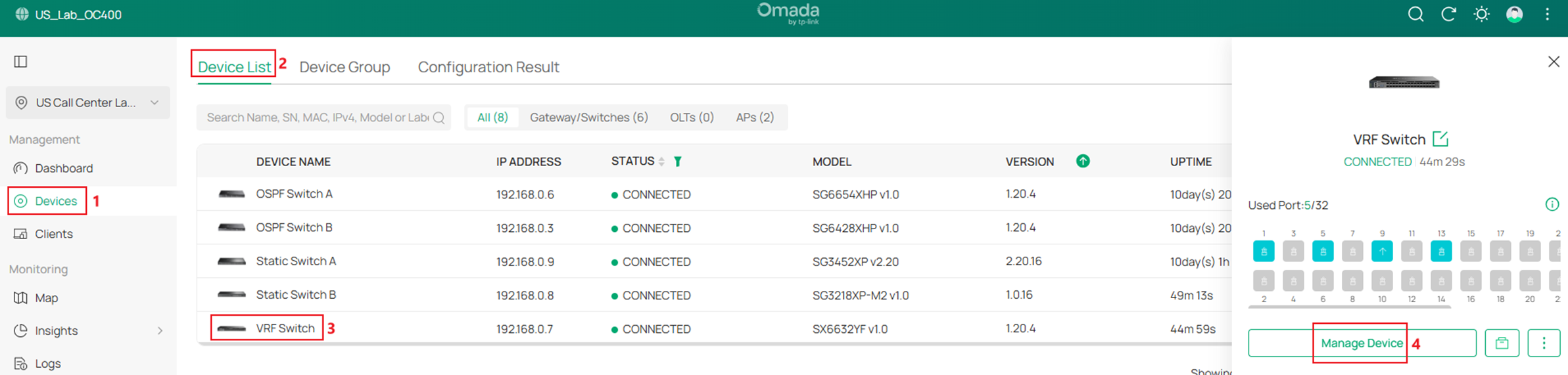
Step 2. Create two VRF instances named VRF1 and VRF2 on the VRF Switch. Go to Devices -> Device List, click on the VRF Switch, on the pop out page, click Manage Device.

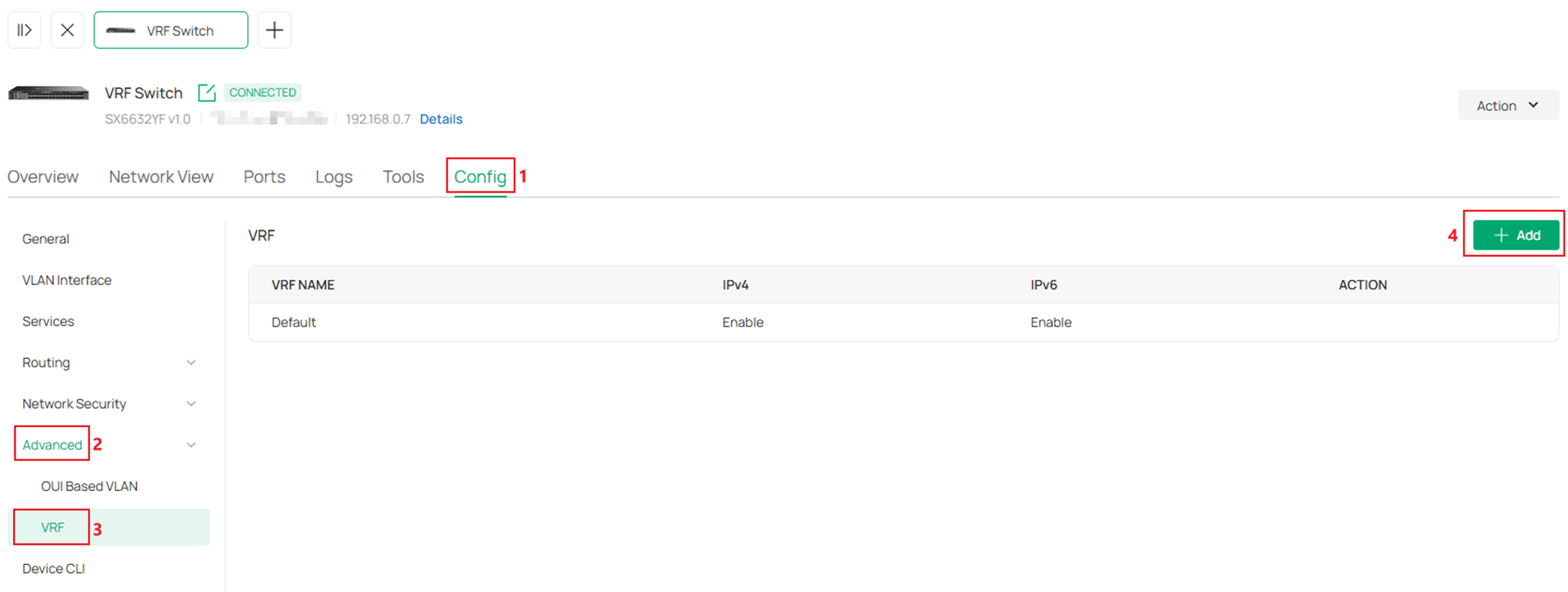
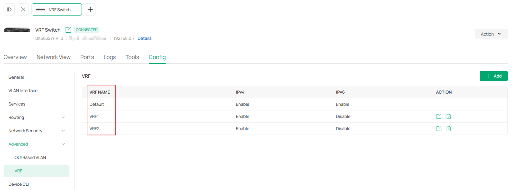
In the switch configuration page, go to Config -> Advanced -> VRF, click Add.
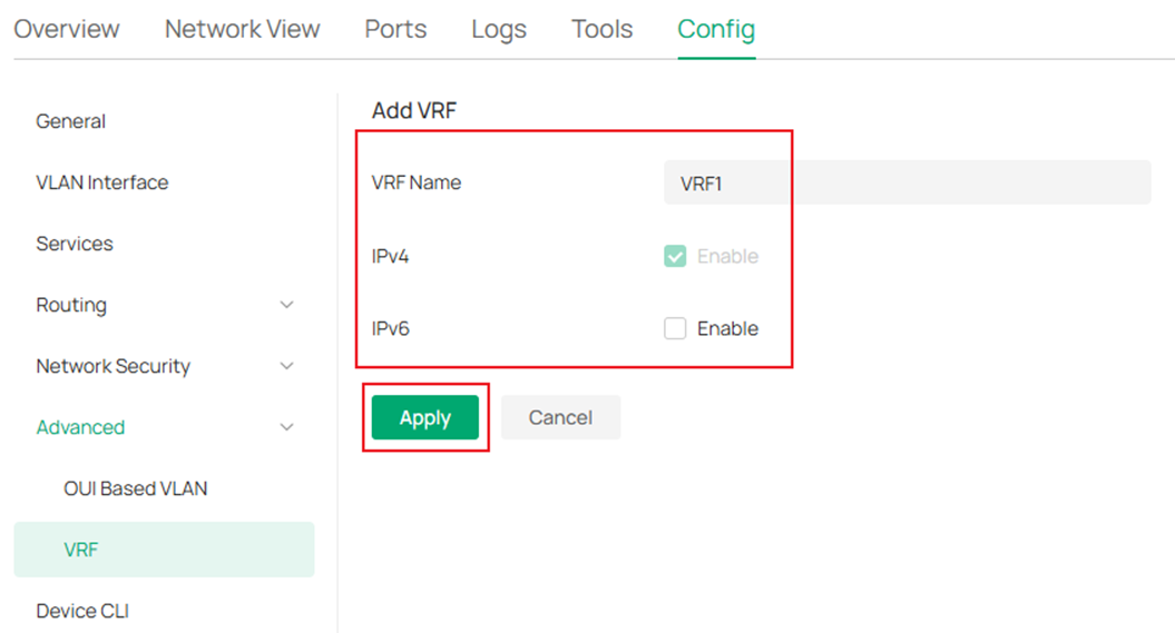
Enter the name of VRF instance, choose whether to enable IPv4 and IPv6 on the instance, click Apply to create.
Create VRF 2 as the same process. The result should be:
Step 3. Create the VLANs and interfaces involving the VRF instances on VRF switch, which are VLAN 101, 102, 201 and 202.
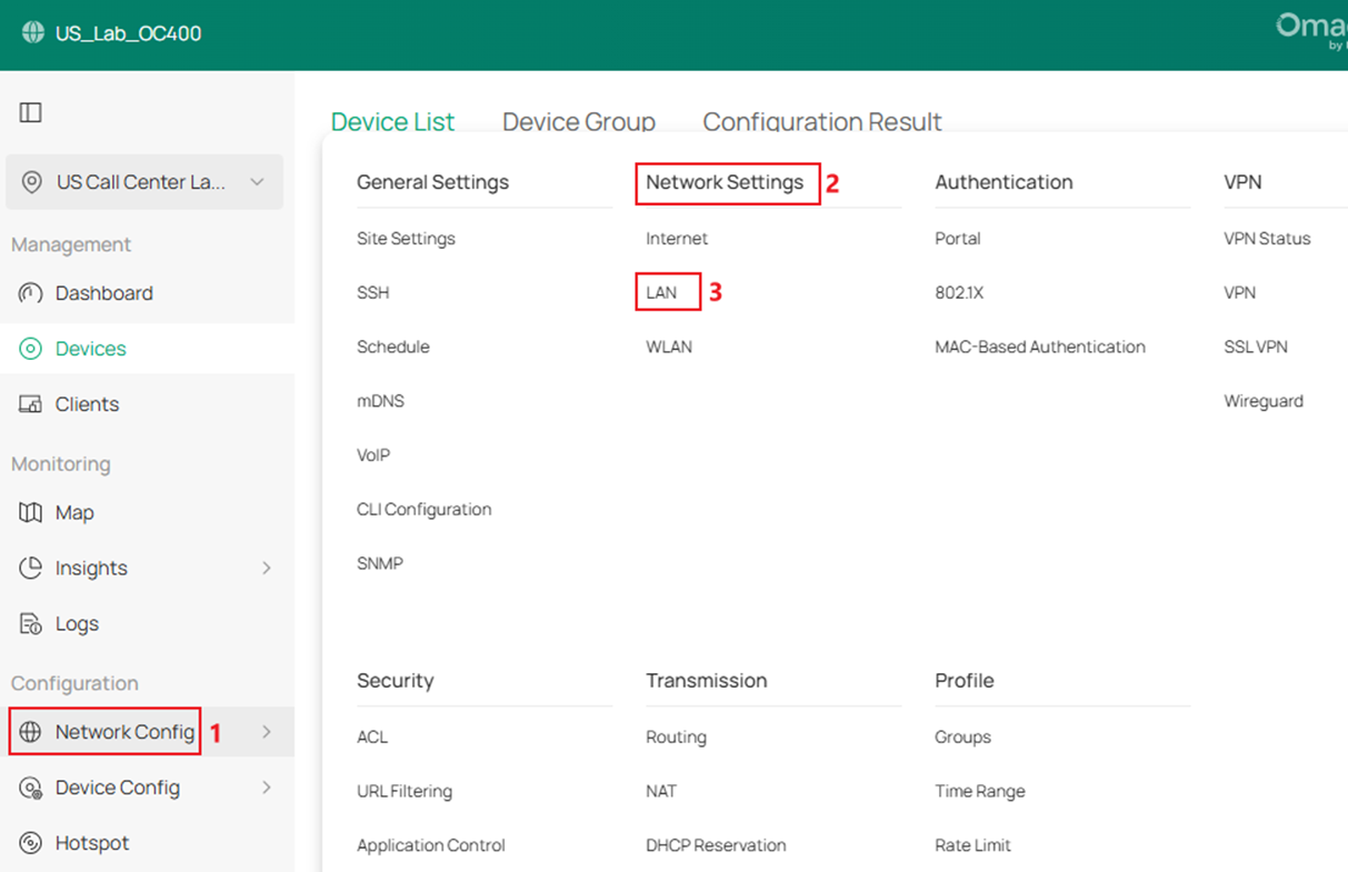
Go to Network Config -> Network Settings -> LAN.
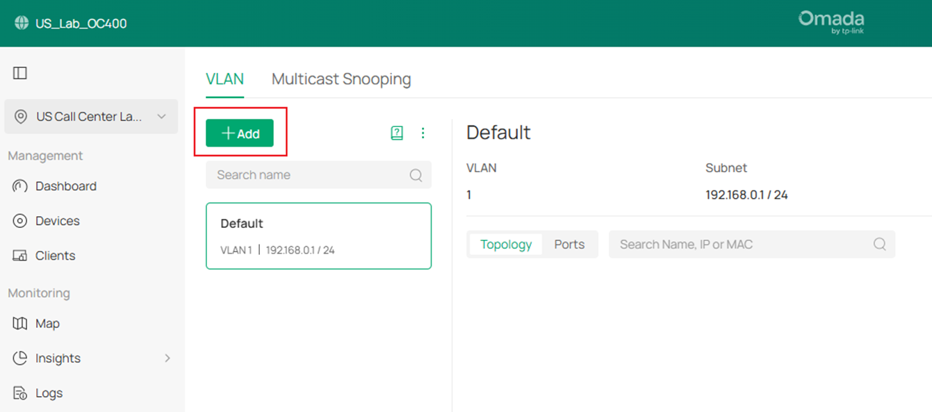
Click Add to create a new LAN.
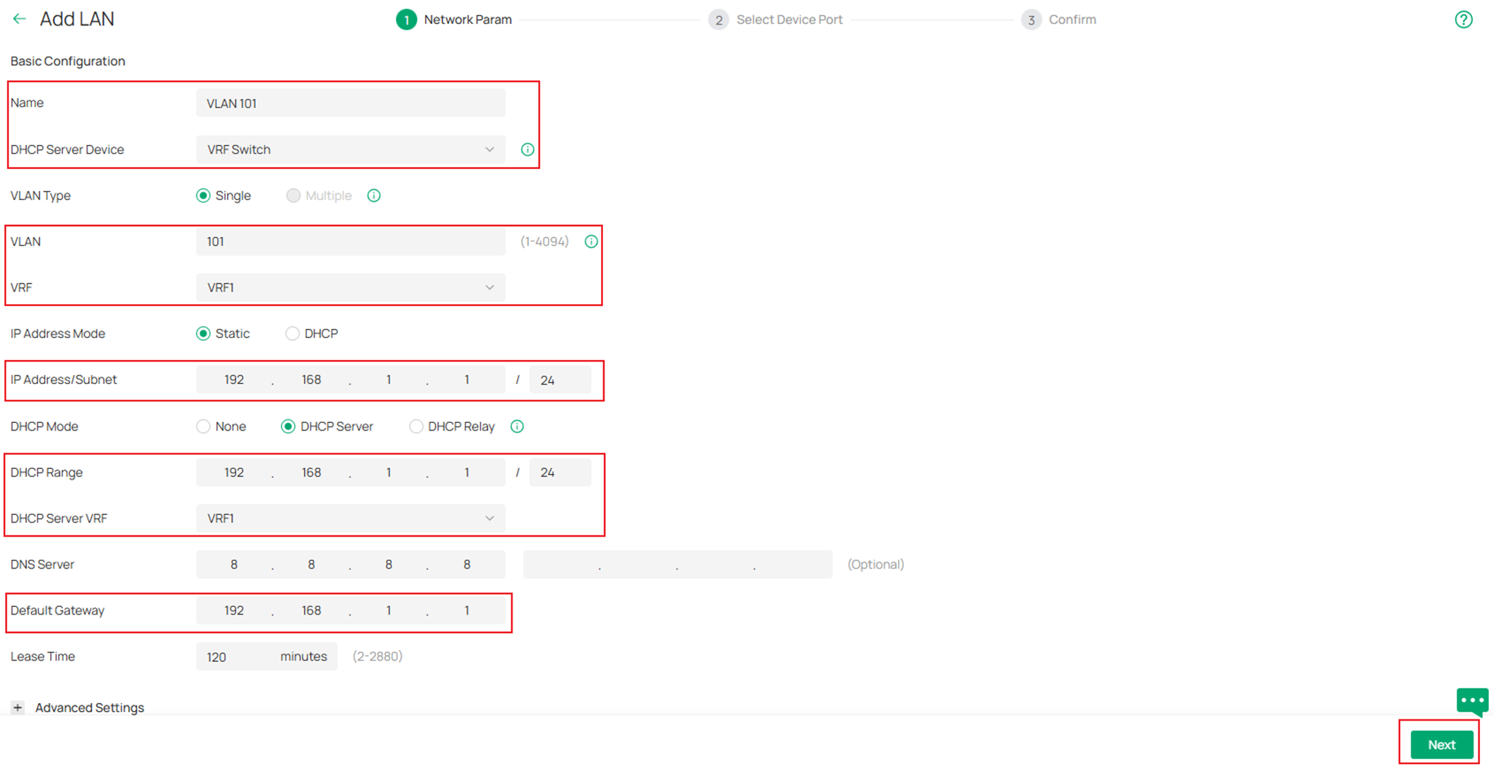
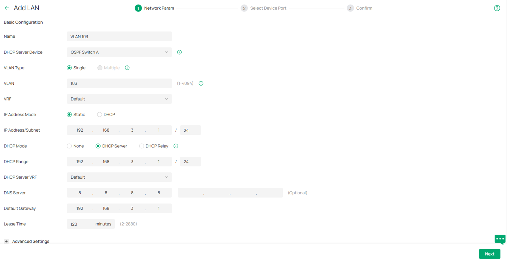
Obviously, we will be using the VRF Switch as the default gateway for these networks, while creating these networks, we could select the VRF Switch as the DHCP Server Device, this way, the corresponding VLAN interfaces will be created together on the VRF Switch along the VLANs. Here we could just set the VRF Switch as DHCP server for these networks by setting DHCP Mode as DHCP Server. If you wish to use other devices as the DHCP server, set the DHCP Mode as None. Enter or select the Name, VLAN ID, VRF and other necessary parameters. Click Next to proceed.
On the Select Device Port page, select the access ports as you need and click Next.
On the Confirm page, double check if all the information is correct and click Apply to finish the configuration.
Repeat the steps above and finish creating VLAN 101, 102, 201 and 202.
Step 4. Create the rest VLANs and corresponding interfaces, including VLAN 103 and VLAN 203, select the corresponding switch as the DHCP Server Device.
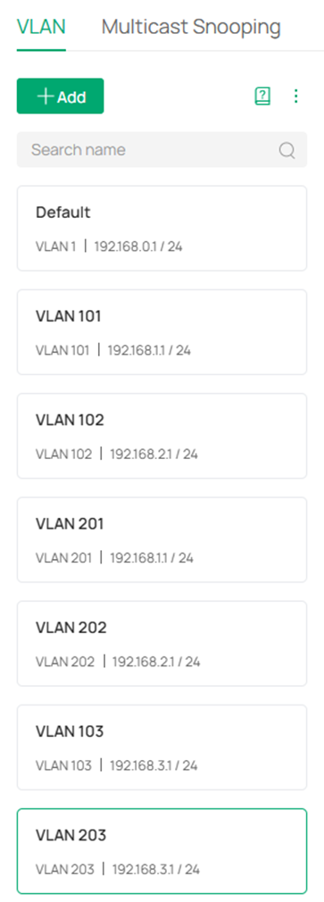
After finish creating all the networks, the VLAN list should be like this:
Step 5. Configure the port VLAN status on all switches, according to the topology, the VLANs should only be existed on certain switches, apart from VLAN 1 is used for management and needs to be existed on all switches, the other VLAN status will be:
On OSPF Switch A: VLAN 101 and 103.
On OSPF Switch B: VLAN 102.
On VRF Switch: VLAN 101, 102, 201 and 202.
On Static Switch A: VLAN 201 and 203.
On Static Switch B: VLAN 202.
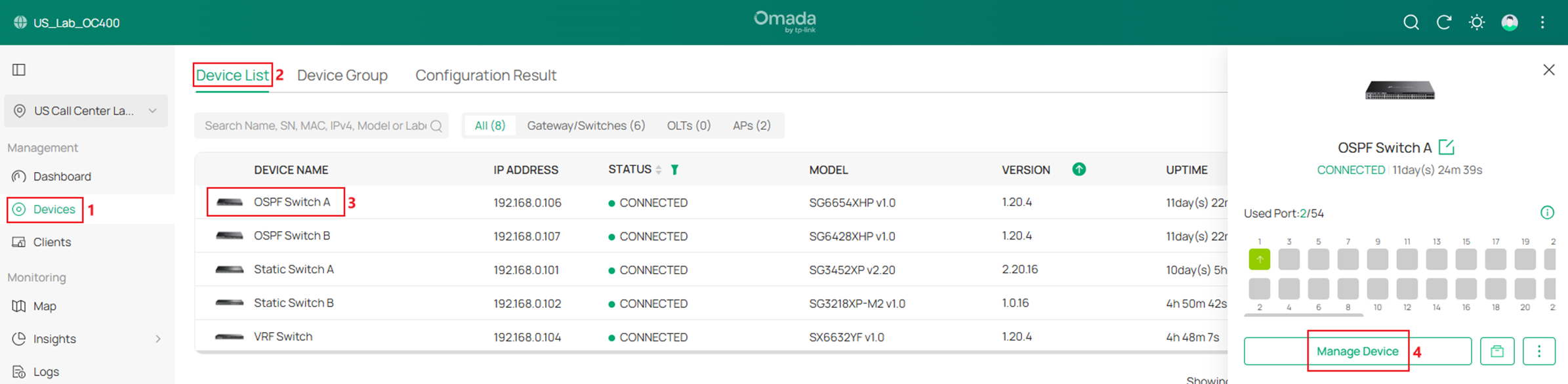
Go to Devices -> Device List, click on a switch, on the pop out page, click Manage Device.
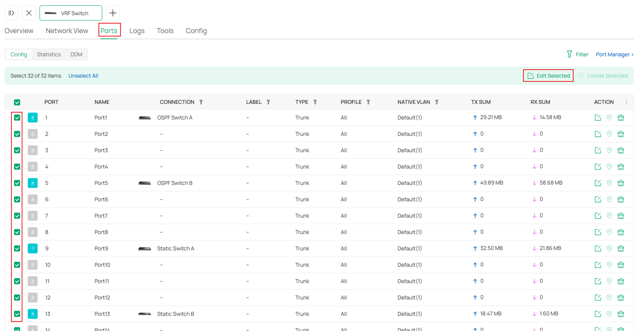
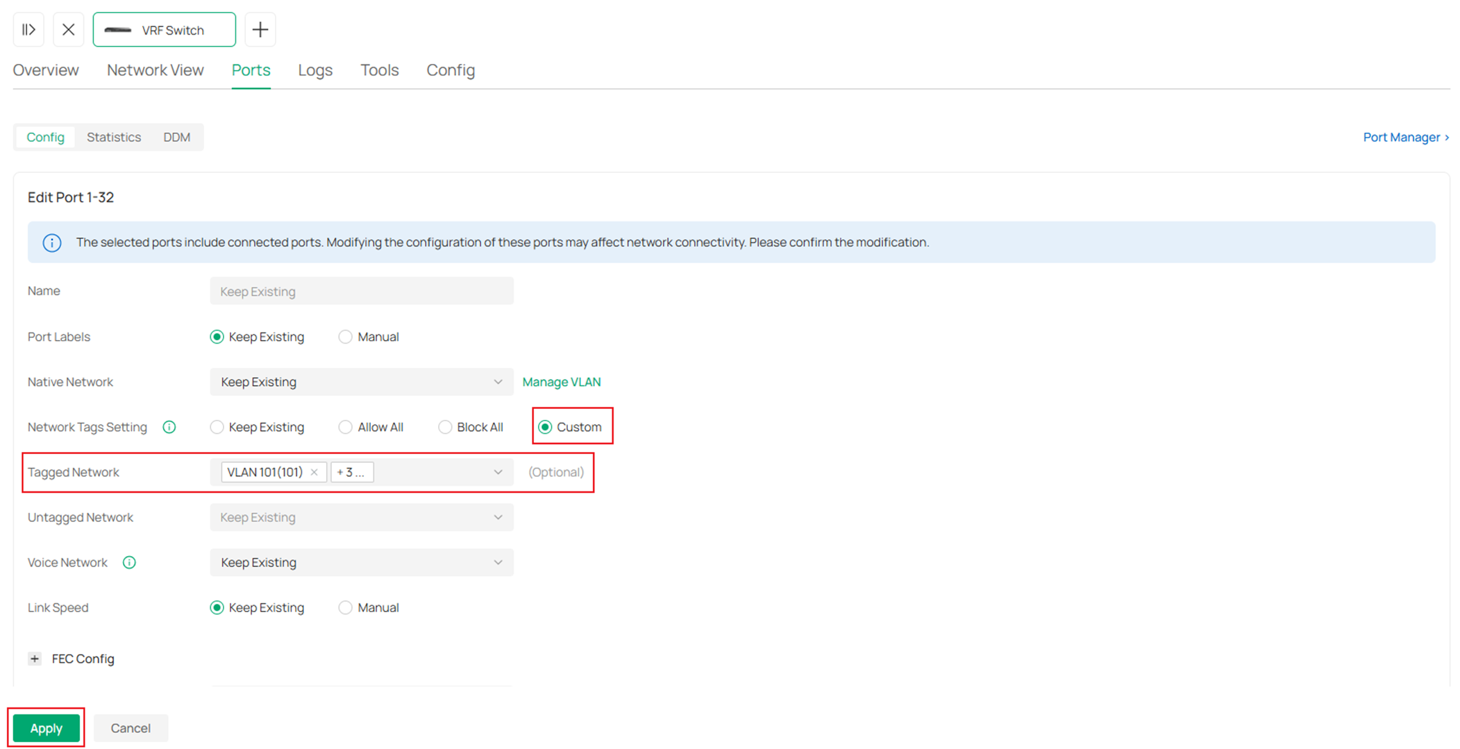
In the switch configuration page, go to Ports, select all the ports except the access ports which have been configured while creating VLANs, click Edit Selected to batch edit the port VLAN status.
In the port configuration page, select Custom for Network Tags Setting, by default, the Native Network should be default VLAN 1, so leave it as Keep Existing here, for Tagged Network, select the VLANs we have listed above for each switch. Click Apply to save.
Repeat the steps above and finish configuring all the port VLAN status for all switches.
Step 6. Enable the other VLAN interfaces. Till now, we have enabled all interfaces on the VRF switch while creating the networks, also, the VLAN 103 on OSPF Switch A and VLAN 203 on Static Switch A have been enabled. Next, we need to enable the other interfaces on other switches according to the topology.
Go to Devices -> Device List, click on a switch, on the pop out page, click Manage Device.
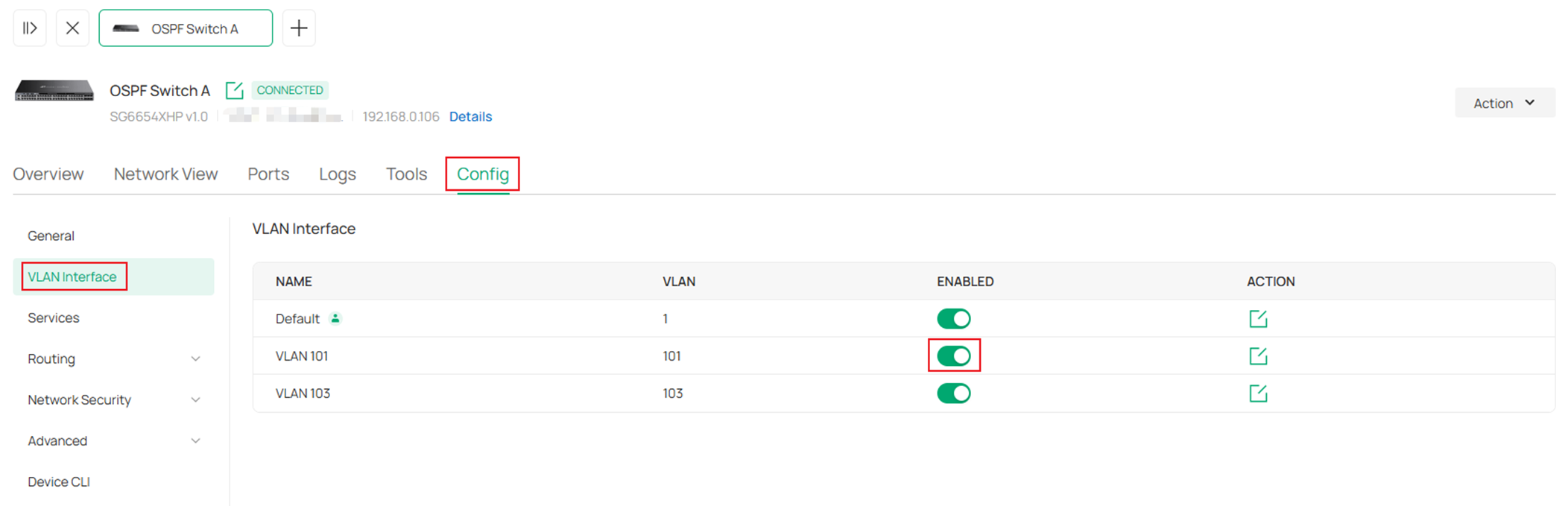
In the switch configuration page, go to Config -> VLAN Interface, click to enable the corresponding VLAN interfaces.
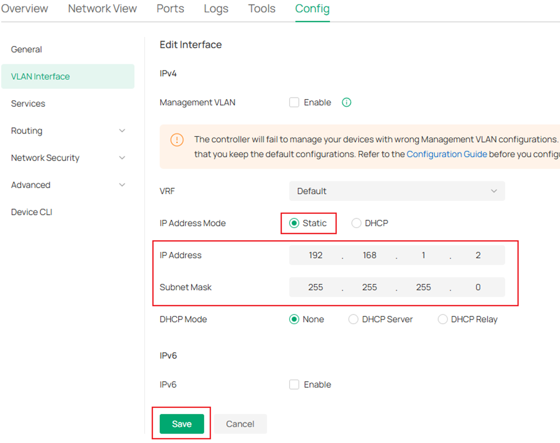
We have enabled DHCP server for these VLAN networks, so we do not need to configure the IP addresses, however, if specific IP addresses were needed, click the Edit button on the right side and set the static IP address, click Save to finish the configuration.
Repeat the steps above and finish configuring VLAN interfaces on all switches according to the topology.
Step 7. Enable OSPF on OSPF Switch A, OSPF Switch B and VRF1 of VRF Switch, we will configure all the networks in area 0, which area ID is 0.0.0.0. Add the corresponding networks into the OSPF process for each switch:
OSPF Switch A: 192.168.1.0/24, 192.168.3.0/24.
OSPF Switch B: 192.168.2.0/24.
VRF Switch: 192.168.1.0/24, 192.168.2.0/24.
Go to Devices -> Device List, click on a switch, on the pop out page, click Manage Device.

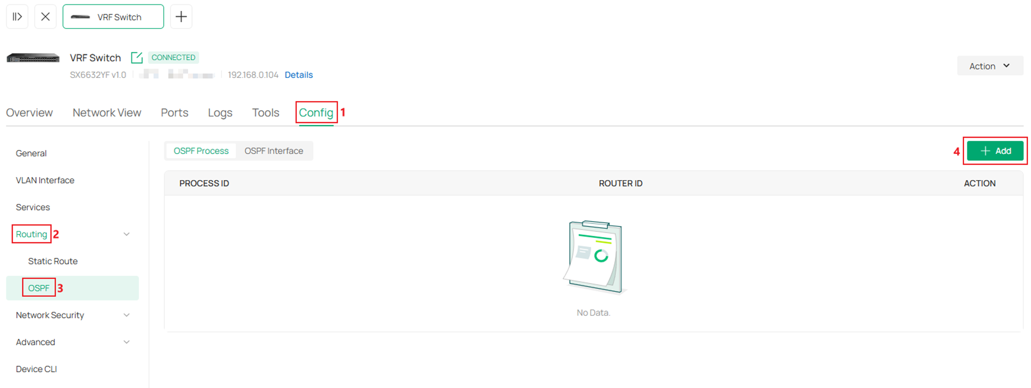
In the switch configuration page, go to Config -> Routing -> OSPF, click Add.
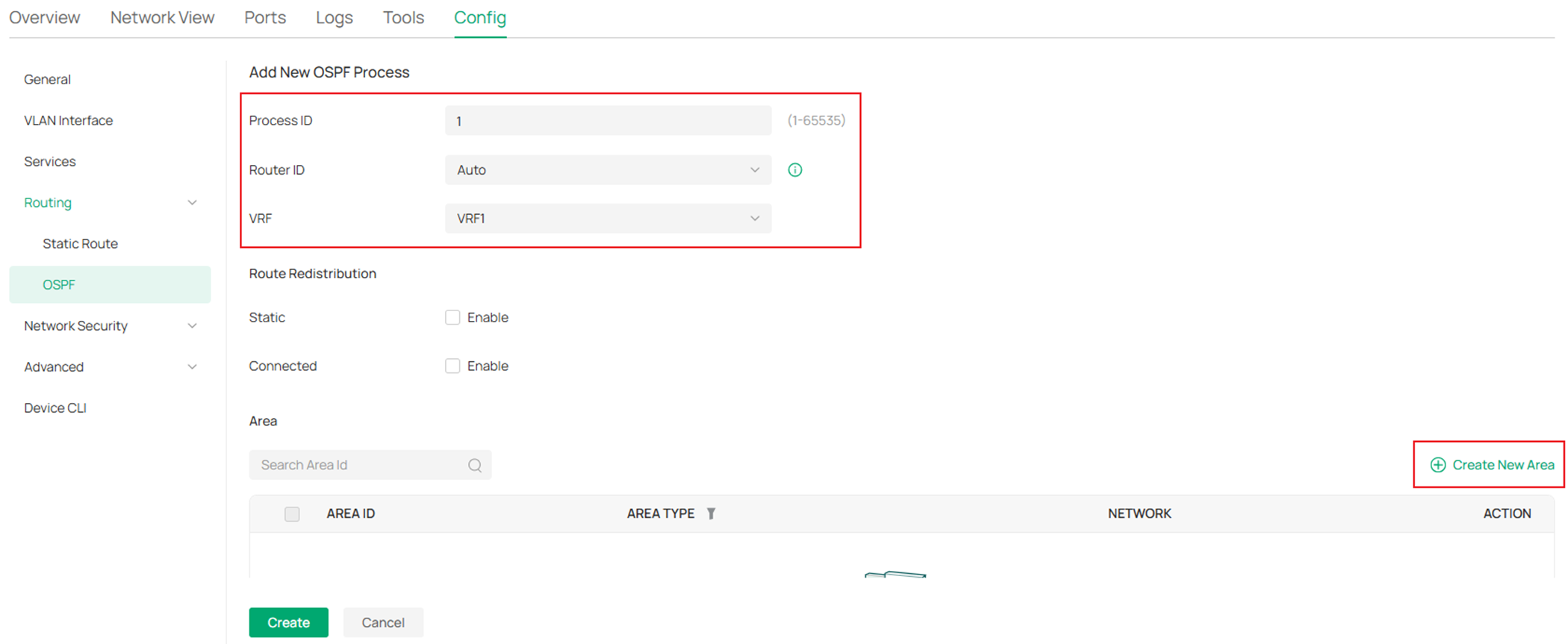
In the Add New OSPF Process page, enter a Process ID, for Router ID, select Auto, as we are configuring on the VRF Switch, we need to select VRF 1 as the option for VRF, for the other two OSPF switches with no multiple VRF instances created, leave this option as default. In the Area section, click Create New Area.
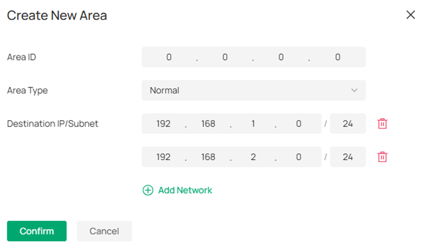
In the Create New Area page, enter the Area ID 0.0.0.0, click Add Network and enter the subnet information, click Confirm to finish the configuration.
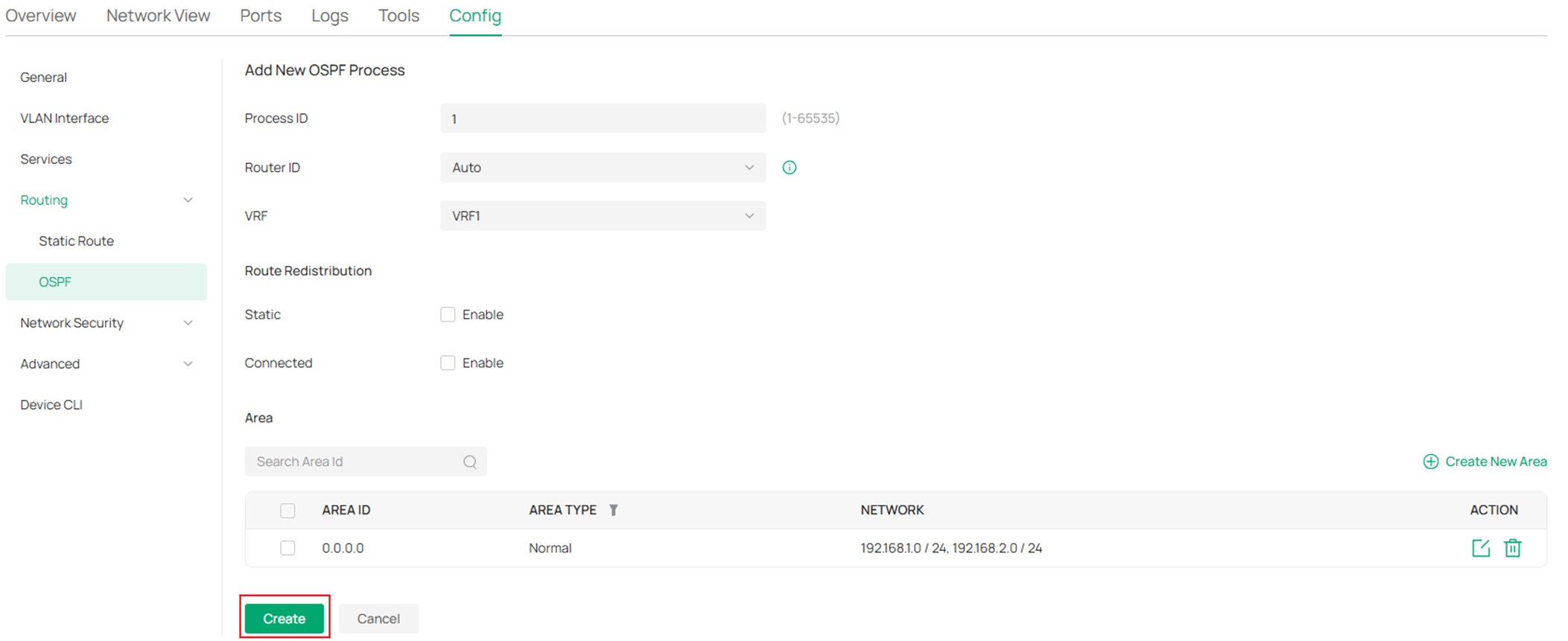
Finally, click Create to finish configuring OSPF on the switch.
Repeat the previous steps and finish configuring OSPF on the other two OSPF switches.
Step 7. Configure a pair of static routes between Static Switch A and VRF2 of VRF Switch to establish the routes between network VLAN 202 and 203:
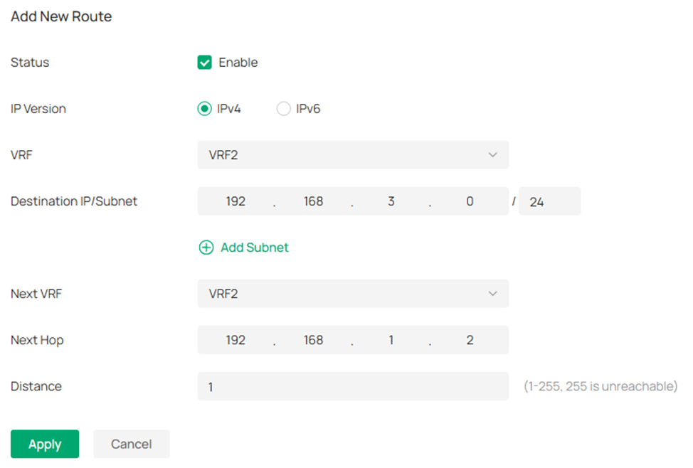
VRF Switch: Destination 192.168.3.0/24, next hop 192.168.1.2 (VRF2)
Static Switch A: Destination 192.168.2.0/24, next hop 192.168.1.1
Go to Devices -> Device List, click on a switch, on the pop out page, click Manage Device.

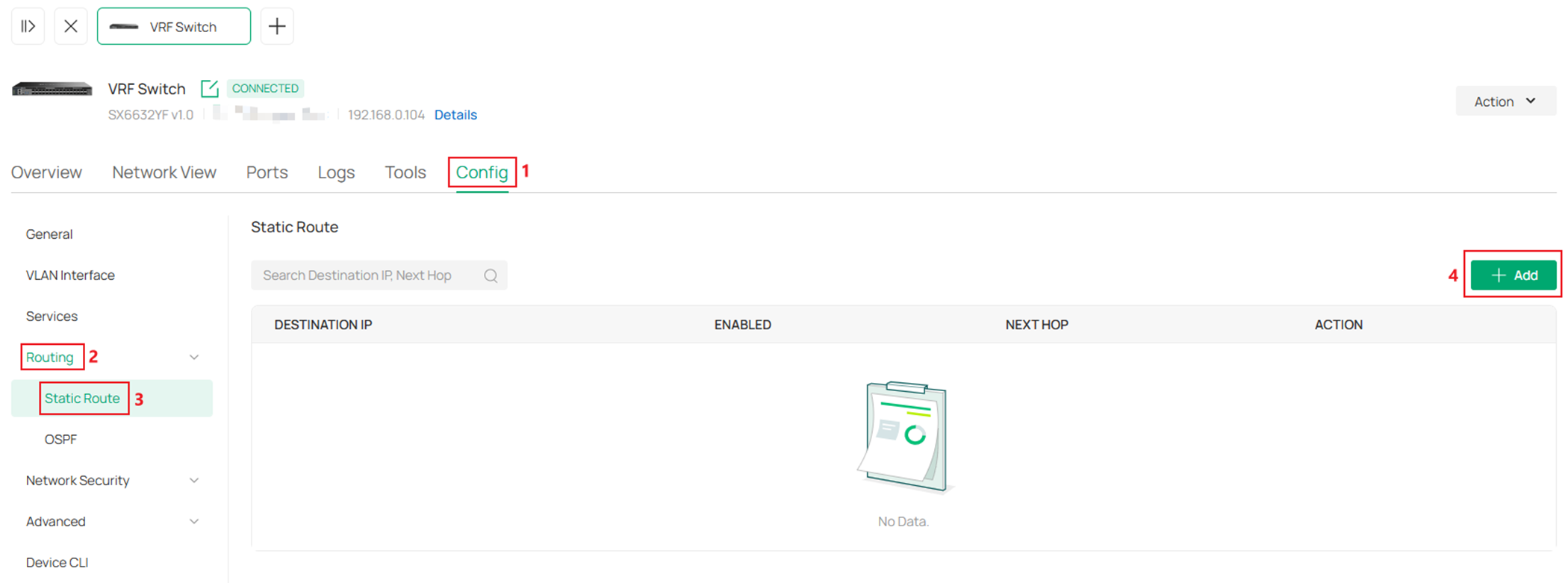
In the switch configuration page, go to Config -> Routing -> Static Route, click Add.
Click to Enable the Status, select VRF2 for VRF option, enter the Destination IP/Subnet, Next VRF and Next Hop, click Apply to finish the configuration.
Repeat the previous steps and configure static route on the other switch.
Here we have finished the configuration of VRF based on the given example topology, there are different VLAN interfaces and networks using same IP address and subnet address without causing any conflict within the topology. Also, VRFs are able to carry static and dynamic routings across the network, so the networks in the same VRF instance could communicate with each other via IP routes but will not be able to communicate with networks in different VRF instances due to the independent routing tables.
Verification
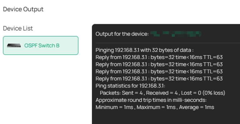
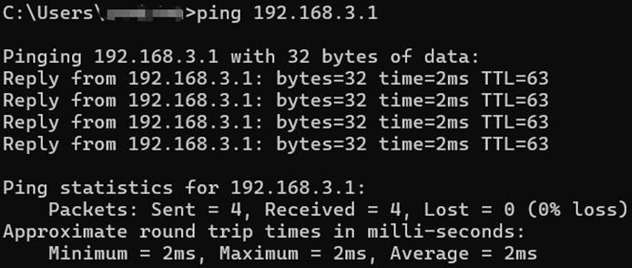
After finishing the configuration, we should be able to ping the interface VLAN 103 on OSPF Switch A from OSPF Switch B and ping the interface VLAN 203 on Static Switch A from the PC connecting to Static Switch B.
As we have introduced, the VRF instances will operate independent routing tables, we could go to the switch configuration page, in Network View -> Routing Table to check the different routing tables on a single device.
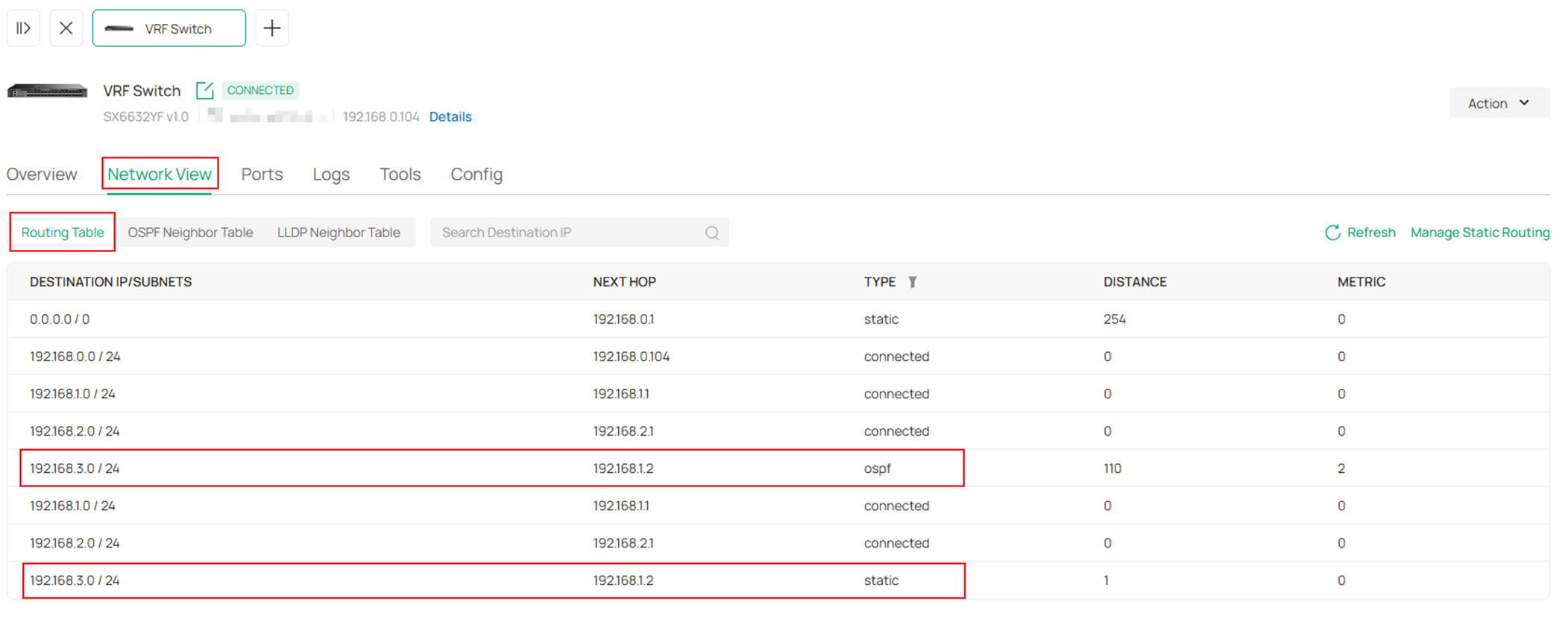
As we could see here, there are routes towards the same destination with same next hop, they are not duplicated because they are formed within differnet VRF instances.
There are two routes which destination is 192.168.3.0/24 and next hop is 192.168.1.2. For the first route which destination is 192.168.3.0/24, the Type is ospf, which means this route is formed by OSPF, For the first route which destination is 192.168.3.0/24, the Type is static, which means this route is a static route manually created.
These results is expected from the example topology and configuration, indicating the VRF is operating without a problem and we could also configure other features in different VRF instances.
Conclusion
In this article, we briefly introduced what VRF is and gave an example on how to configure VRF to realize the feature of separating networks on the same device based on a simple topology.
Get to know more details of each function and configuration please go to Download Center to download the manual of your product.
