


Contents
Configuration for Stacking in Standalone Mode - GUI
Configuration for Stacking in Standalone Mode - CLI
Configuration for Stacking in Controller Mode – Adopt to Controller First then Stack
Configuration for Stacking in Controller Mode – Stack First then Adopt to Controller
Introduction
Stack is a device virtualization technology that connects two and above switches supporting stack features via cables through their stack ports, which logically virtualize them as one device to forward data in the network in Layer 2 and Layer 3 protocols. Through this feature, switches can be stacked to improve reliability, expand port numbers, increase bandwidth, simplify networking, etc.
There will be one Master Unit in the stacking group, which acts as the primary control plane and the logical leader, or more vividly, the “brain” of this stacking group. Even though all member units contribute ports and forwarding capacity, the stack is managed as one device, and the Master is the unit that represents the whole stacking group to the outside world. Only one unit is Master at a time, the other members operate as Member.
Currently, all Omada stackable switches use uplink port as stacking port, also, there is a limit on which models could be stacked together. The basic principle is that the maximum stacking port (uplink port) speed needs to be the same, but there are also some exceptions, the current status of models which could be stacked together are as follows:
- All SG5 series could be stacked together, including SG5428X, SG5428XF, SG5428XMPP, SG5452X, SG5452XMPP.
- All SG6 series could be stacked together except SX6632YF, including SG6428X, SG6428XHP, SG6654X, SG6654XHP.
- All models in S6500 series could be stacked together starting from firmware version v1.20.1(to configure on controller, controller v6.2.10 or higher is required), including: S6500-24G4XF, S6500-24GP4XF, S6500-24M4Y, S6500-24MPP4Y, S6500-48G6XF, S6500-48GP6XF, S6500-48M6Y, S6500-48MPP6Y. If firmware version is lower than v1.20.1, only the models with same maximum stacking port (uplink port) speed could be stacked together. For example, S6500-24GP4XF could stack with S6500-48GP6XF but could not stack with S6500-24MPP4Y.
- SX6632YF, S7500-26XF6Y, S7500-24Y4C, S7500-48XF4C, S7500-32C and S7500-48Y8C could only stack with the same model of themselves.
Apart from the restriction on models, the following restrictions must be followed as well:
- When stacking, the stacking ports must be operating at highest port speed available, take SG6428X and SG6654X as example, although their uplink ports speed could be set as 1G, they could only stack while uplink ports speed set as 10G. For the mix stacking between 10G and 25G S6500 models, the stacking ports will be operating at 10G.
- For SG5 series switches, the maximum stacking unit quantity in the stacking group is 4 for both standalone mode and controller mode.
- For SG6 series switches, the maximum stacking unit quantity in the stacking group is 8 for standalone mode and 4 for controller mode.
- For S6500 and S7500 series switches, the maximum stacking unit quantity in the stacking group is 12 for standalone mode and 4 for controller mode.
- The firmware version of all units in the stacking group must be the same.
We will use the following topology as an example to introduce the stacking configuration:
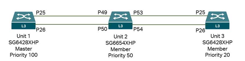
We will introduce the configuration process of stacking in standalone mode and controller mode. For stacking in controller mode, there are two methods: first is to finish the stack in standalone mode and then adopt to the controller, second is to adopt all devices to controller first and then configure stacking on the controller.
Requirements
- Omada SG5, SG6, S6500 and S7500 Series Switches
- Omada Controller
Configuration
Configuration for Stacking in Standalone Mode - GUI
To avoid broadcast storms during the configuration process, it is recommended not to connect the switches using cables at the beginning, only after finished configuring stack info on each device, connect the stacking ports between them and the stack process will auto start.
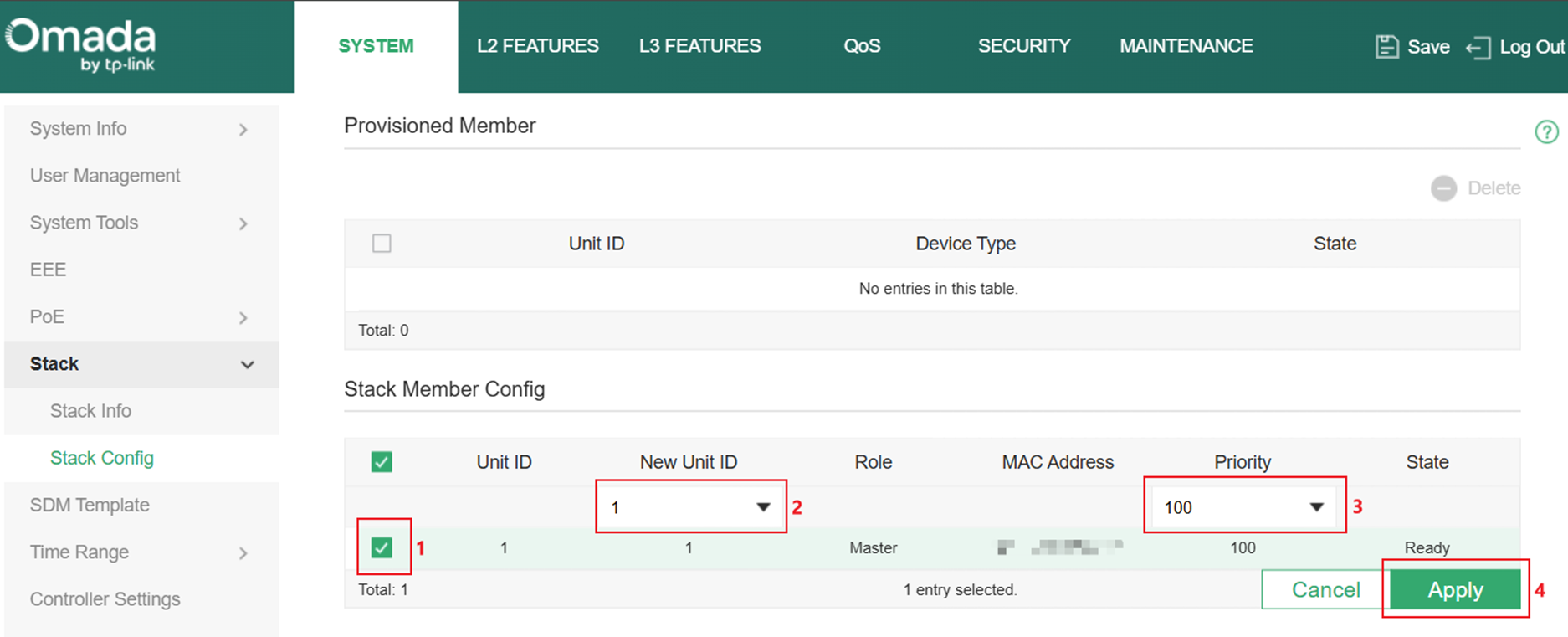
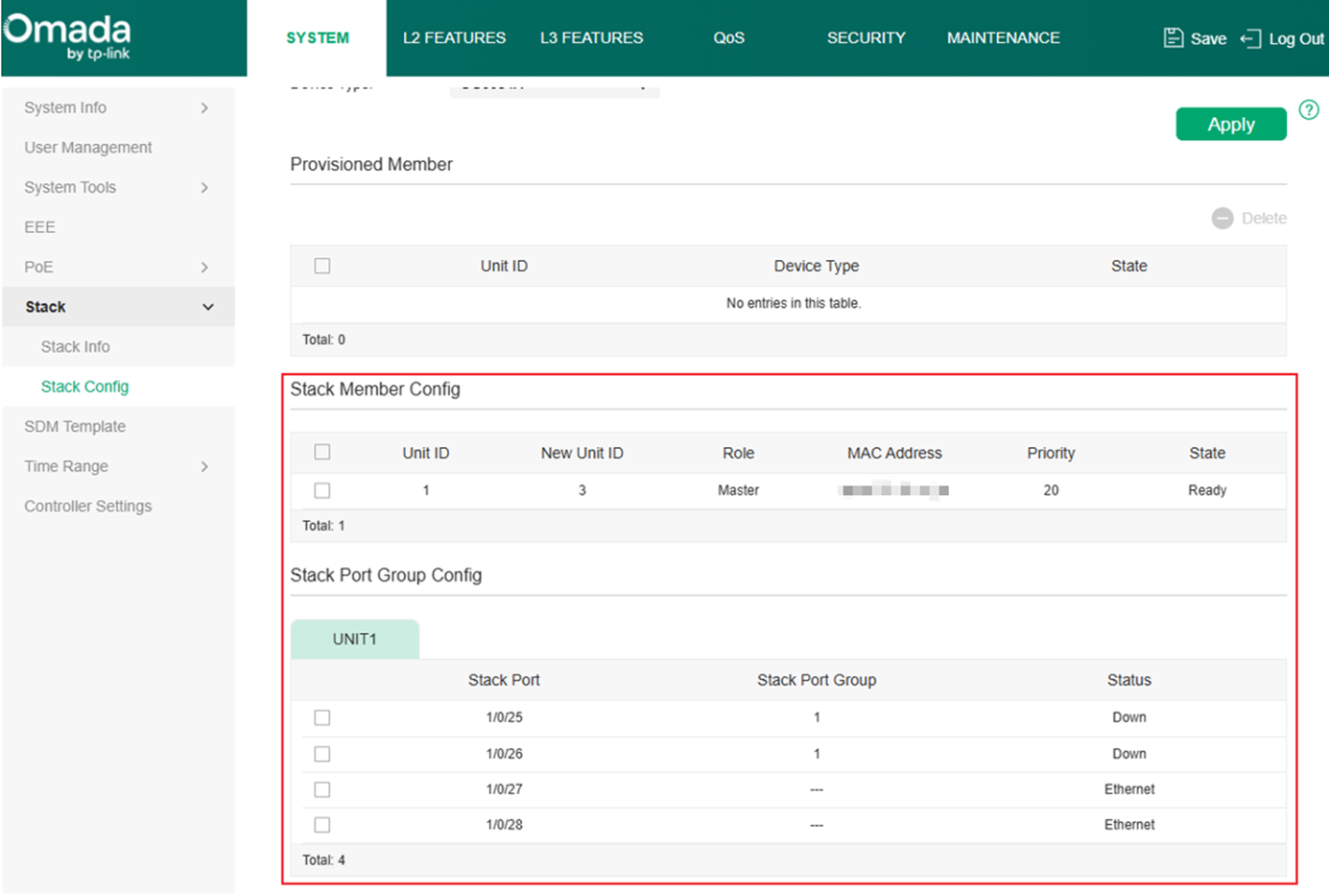
Step 1. Go to SYSTEM > Stack > Stack Config, in Stack Member Config section, setup the New Unit ID and Priority according to the example topology.
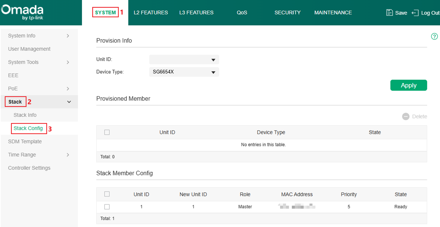
When not stacked with another switch, each switch considered as “solo stack”, so the default Unit ID is always 1, we need to override it with New Unit ID based on the network plan. If Unit ID is keep default on all units, the Member Units will be assigned new Unit ID by the Master Unit. The default Priority is 5, it could be set as a value between 1-255, larger the number, higher the priority, which then results in Master Unit election, so the Priority needs to be configured based on user’s network plan. Take the SG6428XHP in the topology as example, it will be Unit 1 and Priority set to 100, click Apply to save the configuration. Configure the parameters accordingly on the other units accordingly.
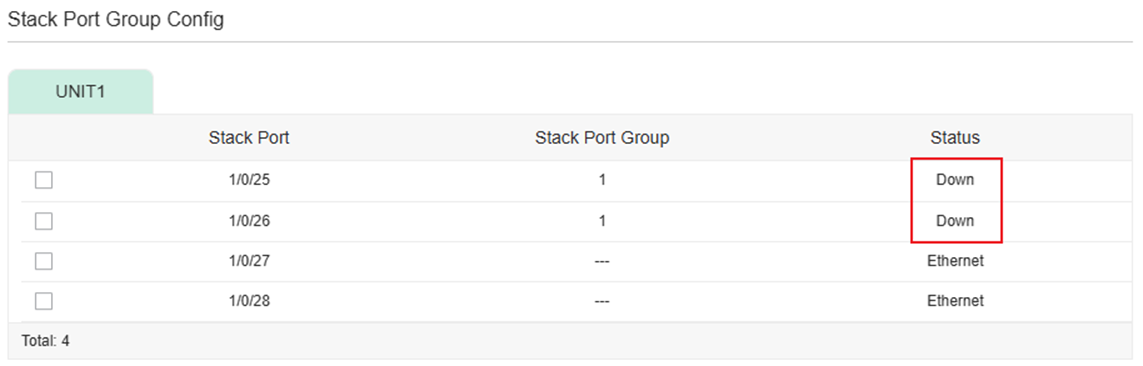
Step 2. Set the uplink ports to stacking mode. In Stack Port Group Config section, the uplink ports will be displayed, by default, their Status are Ethernet, which means they are acting as uplink ports and not ready for stacking. To change the Status, the port must be linked down. Select the ports which will be used to stack with the same unit and assign them a Stack Port Group ID, this ID is only used on the local unit to identify which ports are being used together to stack to a same unit, the ID on peer side unit could be different, as long as the ID is same across ports stacking with same unit. Take the SG6428XHP in the topology as example, select port 25 and 26 and set Stack Port Group ID as 1. Click Apply to save. Configure the parameters accordingly on the other units accordingly.
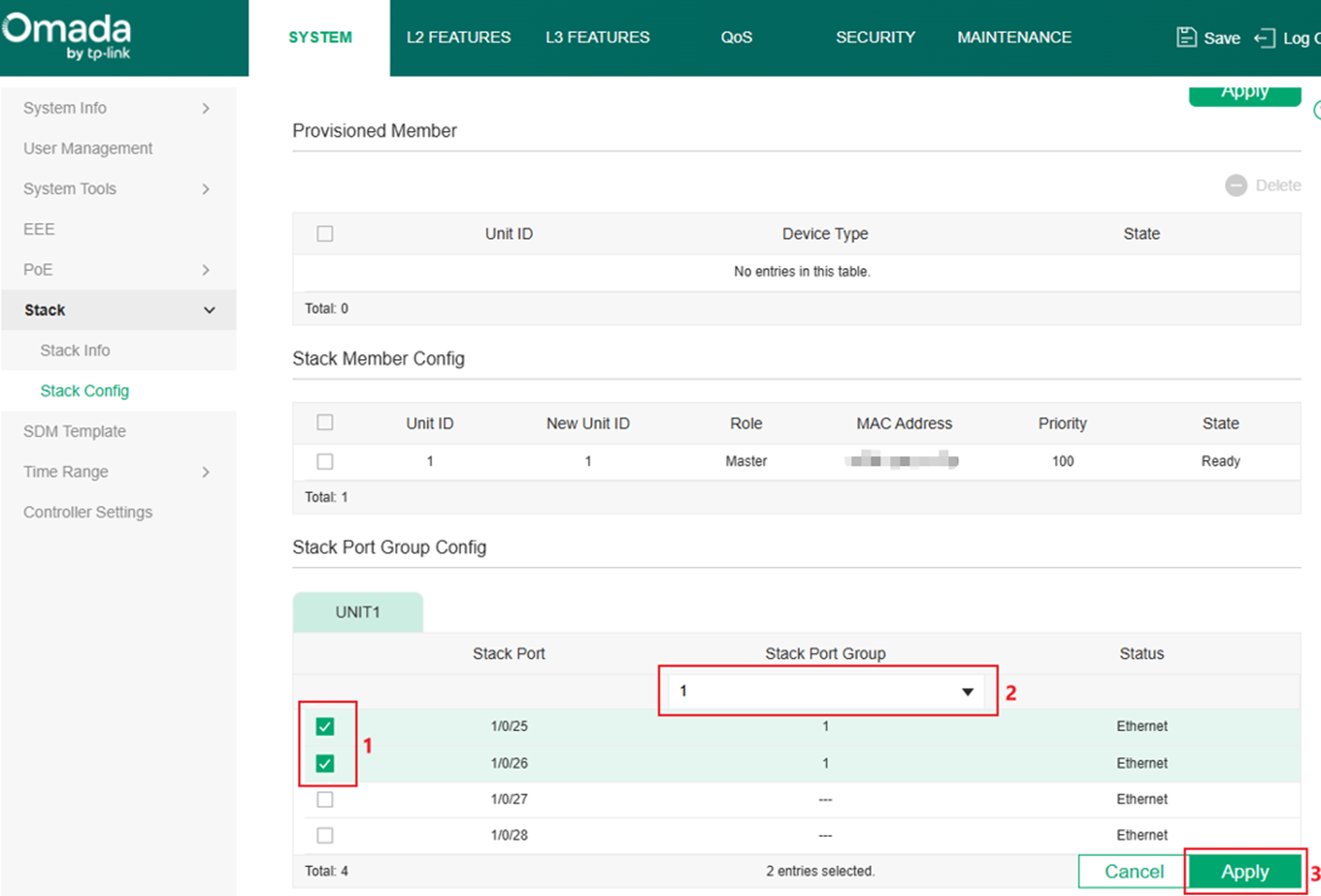
After this configuration, the Status of ports should change to Down, which means the ports have been changed to stacking mode and is not currently stacking to another unit.
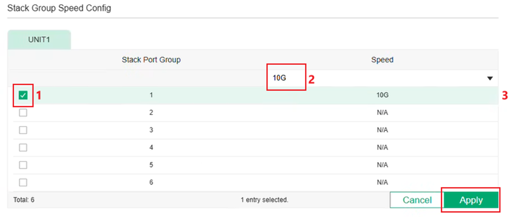
Step 3 (Optional). If stacking between S6500 models with 10G and 25G stacking port, the 25G port needs to adjust speed and operate at 10G speed to stack with 10G models.
- Using 10G cables (Recommended): Auto speed adjustment will be conducted, no additional action needed.
- Using 25G cables: The Stack Group Speed Config in Stack Config page of 25G model needs to be modified, change the Speed to 10G. No additional action needs to be taken on the 10G side.
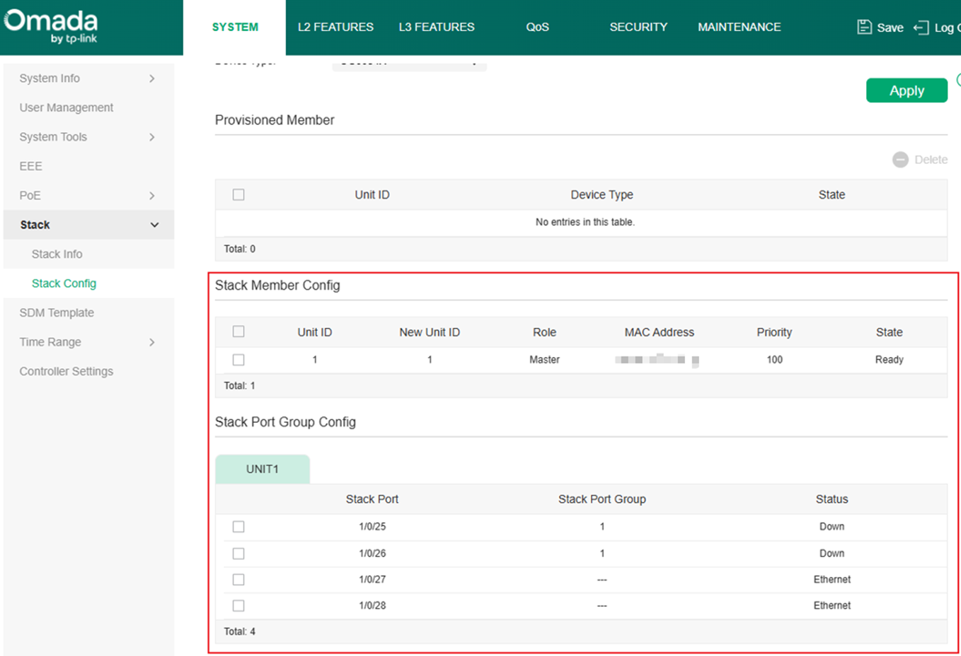
Step 4. After finished the configuration shown in Step 1 and 2, the Stack Config of Unit 1 should be:
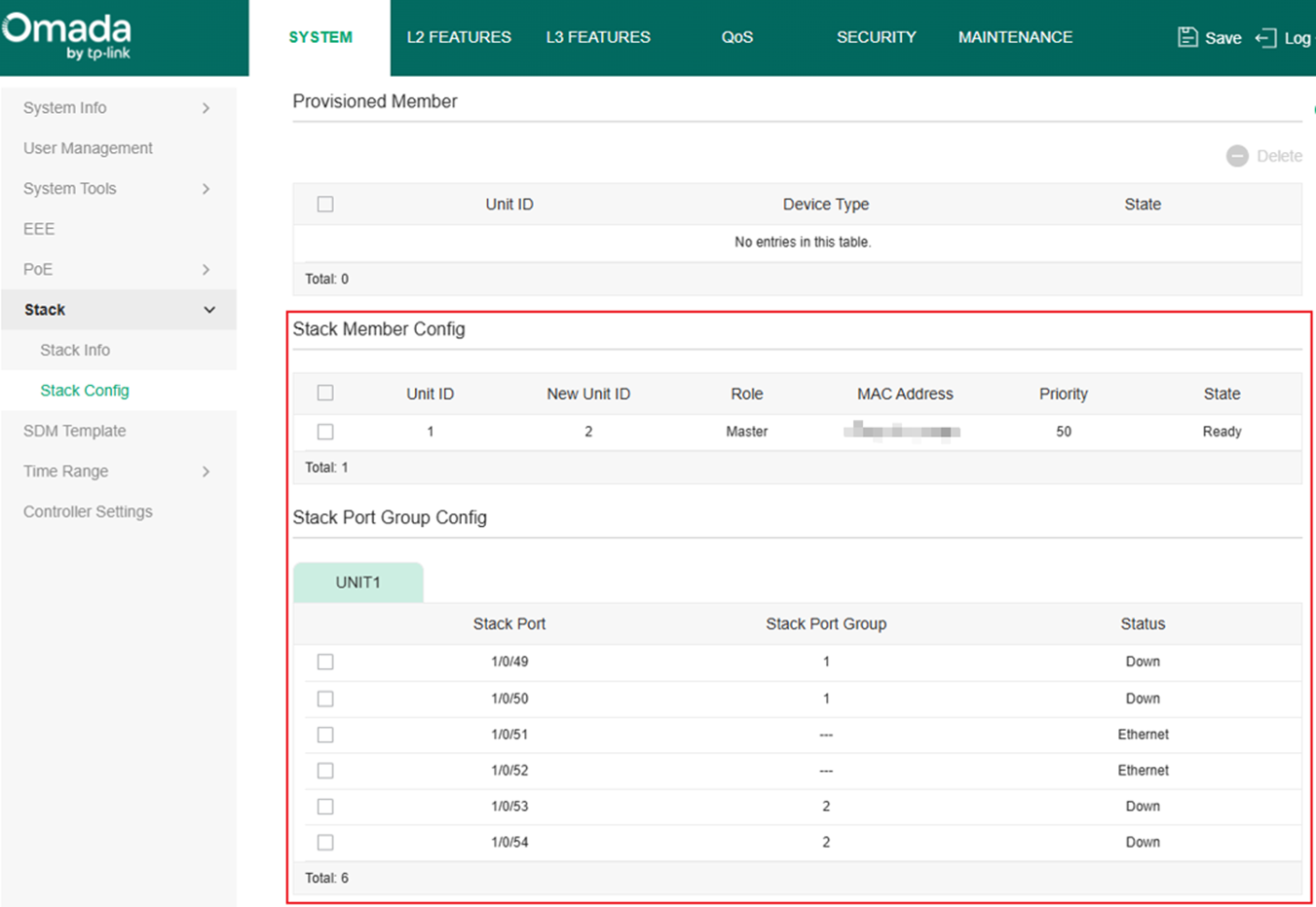
For Unit 2:
For Unit 3:
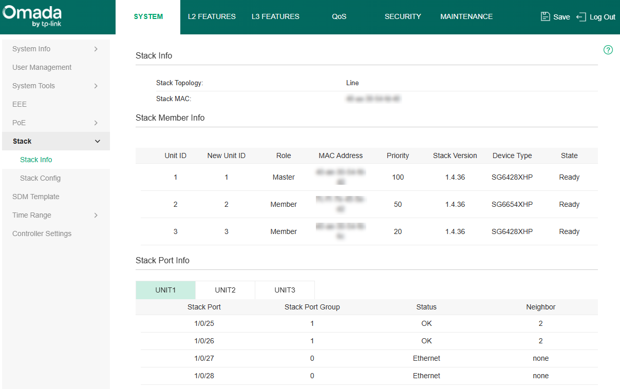
Step 5. Connect the stacking ports configured on units according to the example topology, the stacking process will automatically start. After finished, the three devices will run as a single logical device, login to the IP address of this logical device, the stacking group info could be checked in SYSTEM > Stack > Stack Info.
Configuration for Stacking in Standalone Mode - CLI
To avoid broadcast storms during the configuration process, it is recommended not to connect the switches using cables at the beginning, only after finished configuring stack info on each device, connect the stacking ports between them and the stack process will auto start. All CLI commands shown in this chapter needs to be executed under Global Config View unless specifically stated.
Step 1. Configure the Stack Priority and Unit ID of the unit. Command as follows:
switch <Unit ID> priority <Stack Priority>
Take Unit 1 as example, the command will be:
switch 1 priority 100
Step 2. Create the Stack Group ID and add stacking ports into this group, after this configuration, the ports added will be turned from uplink ports to stacking ports, this could only be done when the ports are in link down state. Please note that the Stack Group ID is only used on the local unit to identify which ports are being used together to stack to the same unit, the ID on peer side unit could be different, as long as the ID is same across ports stacking with same unit. Commands as follows:
switch <Unit ID> stack-group <Stack Group ID>
interface <port>
Take Unit 1 as example, the command will be:
switch 1 stack-group 1
interface 1/0/25
interface 1/0/26
Step 3 (Optional). If stacking between S6500 models with 10G and 25G stacking port, the 25G port needs to adjust speed and operate at 10G speed to stack with 10G models. When 10G intermediate (fiber, DAC, RJ45 transceiver) inserted, the port will detect the intermediate and automatically adjust speed to 10G, no additional procedure is required. If using 25G intermediate, the 25G port will not adjust speed automatically and stack could not be proceeded, port speed needs to be manually adjusted. This action only needs to be taken on 25G model, adjust the stack-group speed to 10G, command as follows (under stack-group view):
speed 10000
If you need to recover it back to 25G, use:
speed 25000
Please note that this action only needs to be done on 25G model side, no additional action required on 10G model side. Also, this command needs to be executed under stack-group view, which is the same view as commands in Step 2 while adding ports into a stack-group.
Step 4. In conclusion, the full set if commands for the three units are as follows.
Unit 1:
switch 1 priority 100
switch 1 stack-group 1
interface 1/0/25
interface 1/0/26
exit
Unit 2:
switch 2 priority 50
switch 2 stack-group 1
interface 1/0/49
interface 1/0/50
exit
switch 2 stack-group 1
interface 1/0/53
interface 1/0/54
exit
Unit 3:
switch 3 priority 20
switch 3 stack-group 1
interface 1/0/25
interface 1/0/26
If using S6500 model with 25G port under the scenario requiring manual port speed adjustment:
switch 1 priority 100
switch 1 stack-group 1
interface 1/0/25
interface 1/0/26
speed 10000
exit
Step 5. Connect the stacking ports configured on units according to the example topology, the stacking process will automatically start.
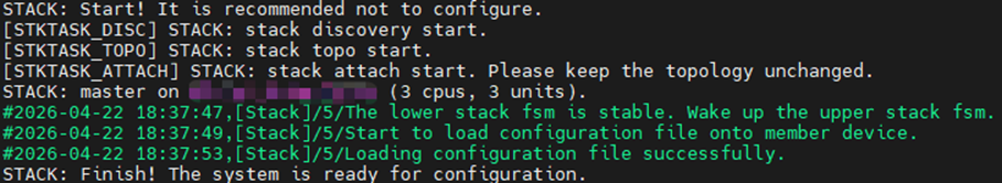
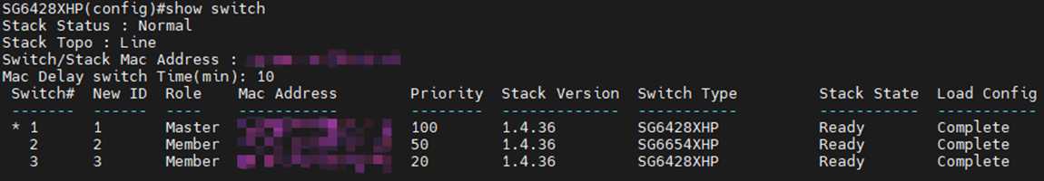
After finished, the three devices will run as a single logical device. Connect to the console of Master Unit or SSH into this logical device, use the following command to check current stacking status:
show switch
To control this device through console, you must be connected to the console of Master Unit.
Configuration for Stacking in Controller Mode – Adopt to Controller First then Stack
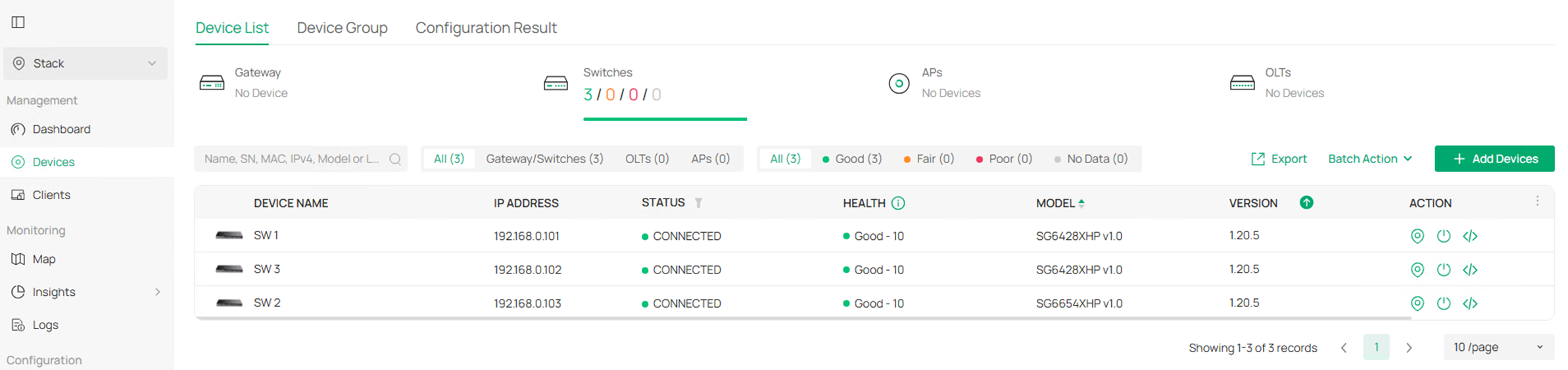
Step 1. Adopt all the switches to controller, if you need to connect the switches together, do not use the uplink ports which are going to be used for stacking as they could not be configured for stacking while linked up.
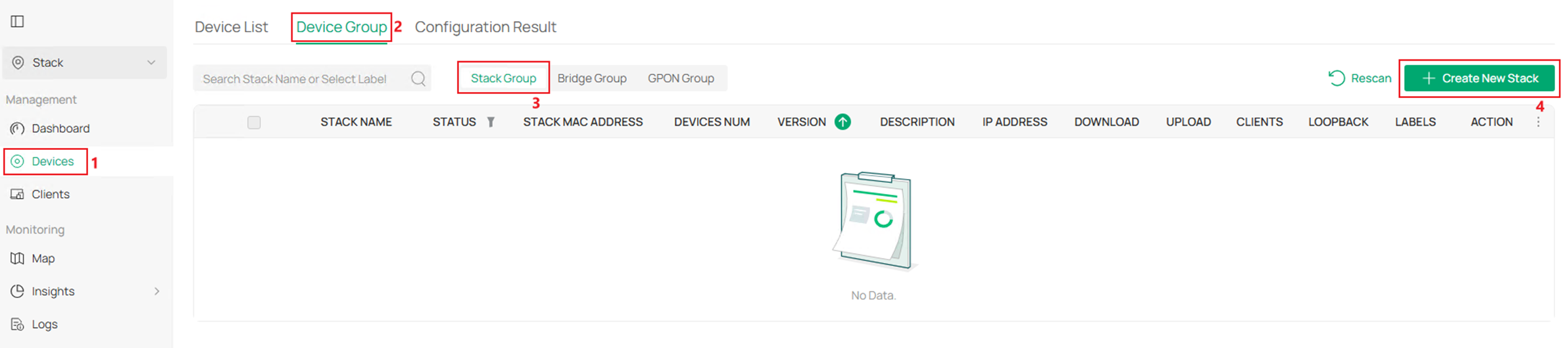
Step 2. Go to Devices > Device Group > Stack Group, click Create New Stack.
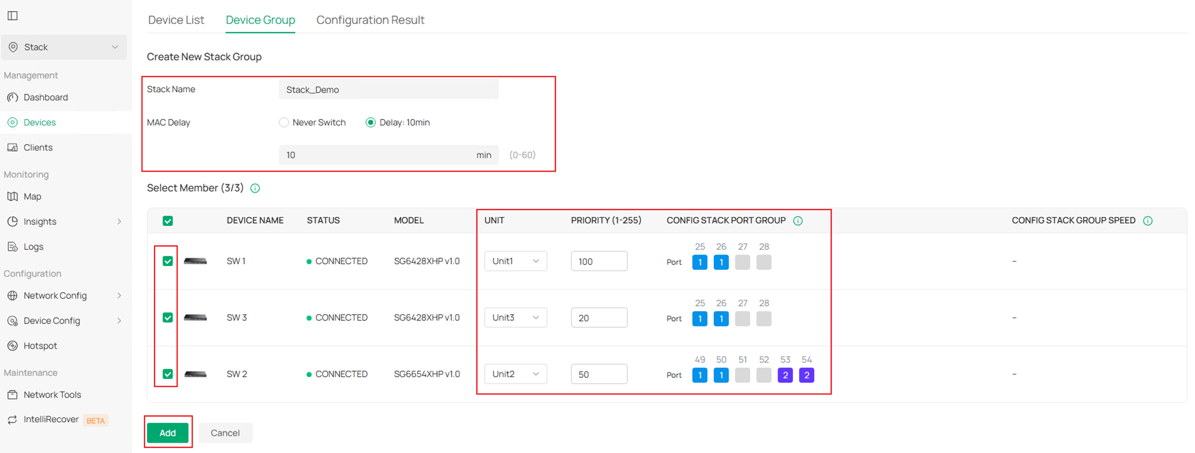
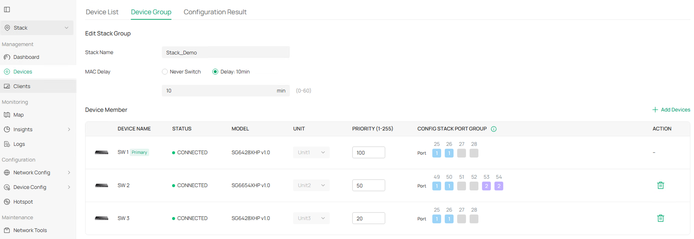
Step 3. Enter the Stack Name, configure MAC Delay as needed, tick all the members ready to stack, assign UNIT ID, configure PRIORITY and CONFIG STACK PORT GROUP. Click Add to finish creating the stacking group.
The PRIORITY could be set as a value between 1-255, larger the number, higher the priority, which then results in Master Unit election, so the PRIORITY needs to be configured based on user’s network plan. Please note that the STACK GROUP ID is only used on the local unit to identify which ports are being used together to stack to the same unit, the ID on peer side unit could be different, as long as the ID is same across ports stacking with same unit.
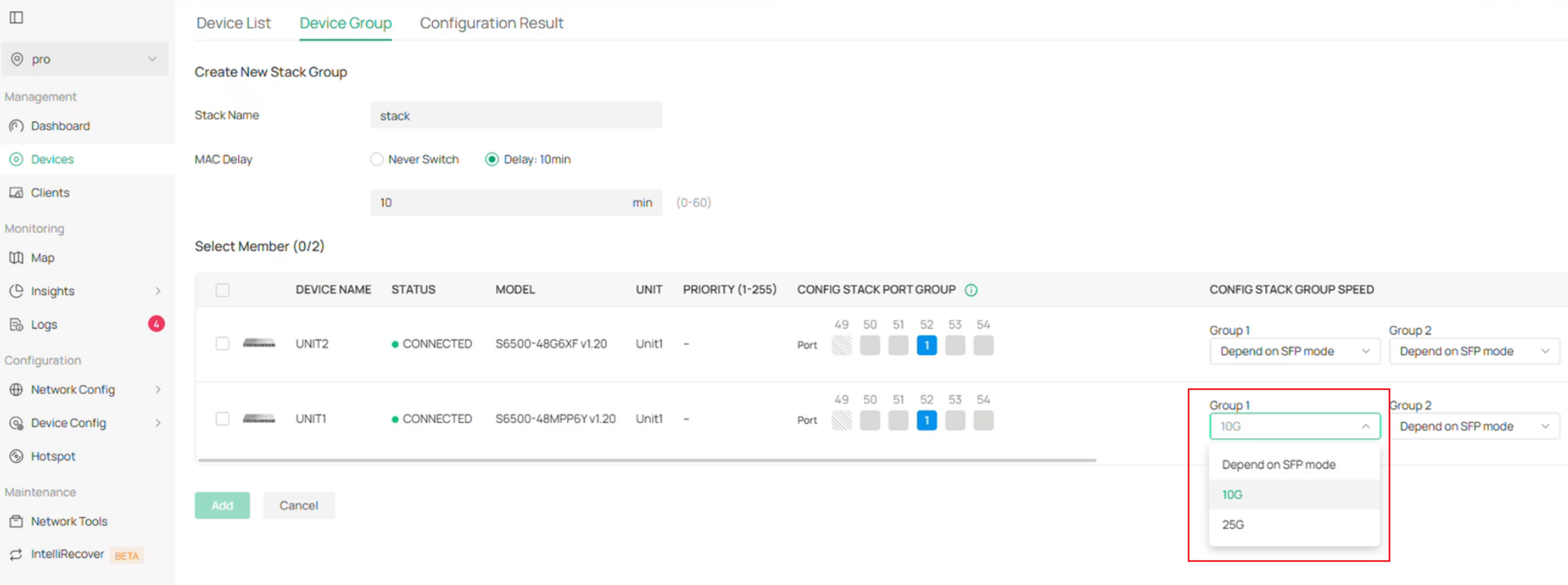
Step 4 (Optional). If stacking between S6500 models with 10G and 25G stacking port, the 25G port needs to adjust speed and operate at 10G speed to stack with 10G models.
- Using 10G cables (Recommended): Auto speed adjustment will be conducted, no additional action needed.
- Using 25G cables: Click to expand the CONFIG STACK GROUP SPEED option on 25G model and set the STACK GROUP SPEED to 10G, this action only needs to be done on 25G side
Step 5.After created, the stacking group is in ABNORMAL status as the stack link is not yet connected.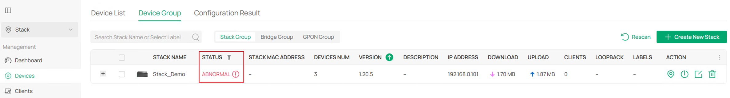
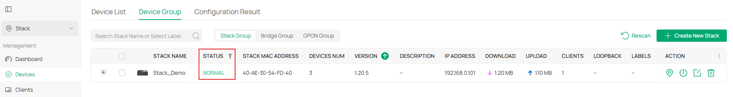
Connect the stacking ports configured on units according to the example topology. After finished, the stacking group should turn to NORMAL status.
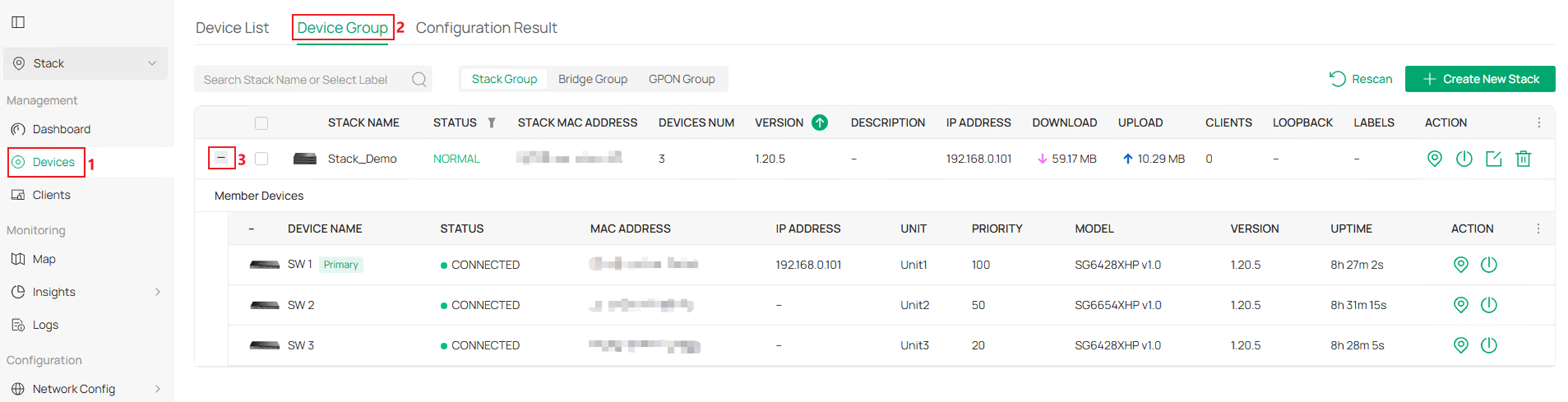
Step 6. To check the stacking group info, go to Devices > Device Group, click to expand the stacking group.
Step 7. To make configuration on the stacking logical device, click on the stacking group in Device Group page, it could not be configured via the units in Device List.

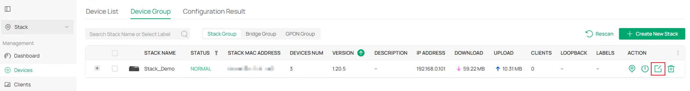
Step 8. To edit the stack status, click the Edit button on the stacking group.
As the stacking group is already formed, the UNIT ID and existed Stack Port Group cannot be modified. To modify existed Stack Port Group on controller, it’s recommended to configure another idle uplink port as stack port for transfer, then cancel the original stack port configuration.

Configuration for Stacking in Controller Mode – Stack First then Adopt to Controller
For this chapter, we will stack the devices in standalone mode first and then adopt to controller as a whole. Please refer to previous chapter for how to stack devices in standalone mode. Then follow the steps listed below:
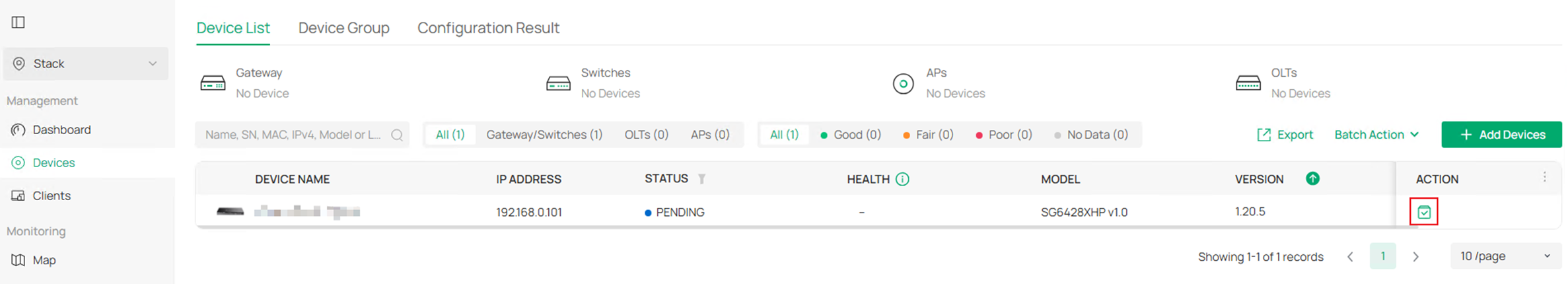
Step 1. After stacked, the Master Unit will show on controller on behalf of the stacking group. Click the Adopt button to adopt this stacking group.
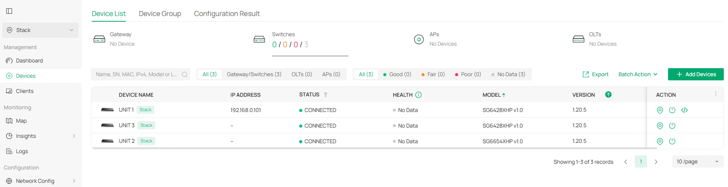
After adopted, the member units will be detected and shown on controller:
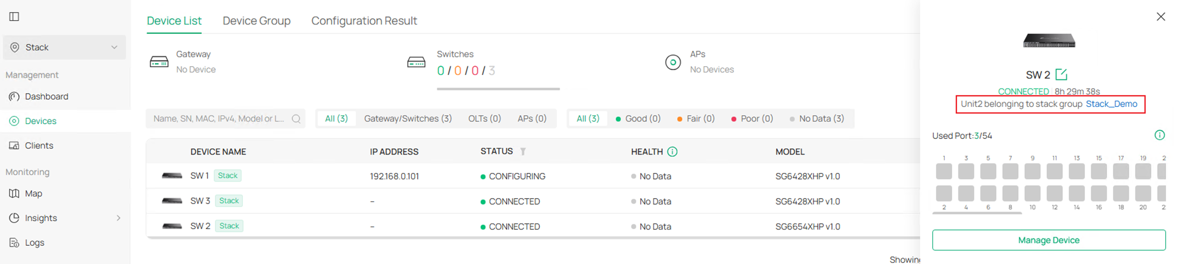
Click into one of the units, the Unit ID will be displayed in the detail page.
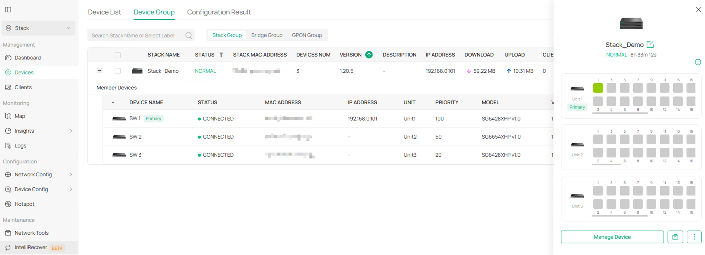
Step 2. To check the stacking group info, go to Devices > Device Group, click to expand the stacking group.

Step 3. To make configuration on the stacking logical device, click on the stacking group in Device Group page, it could not be configured via the units in Device List.
Step 4. To edit the stack status, click the Edit button on the stacking group.

As the stacking group is already formed, the UNIT ID and existed Stack Port Group cannot be modified. To modify existed Stack Port Group on controller, it’s recommended to configure another idle uplink port as stack port for transfer, then cancel the original stack port configuration.
Conclusion
Briefly summarize the configuration results in one or two sentences.
Get to know more details of each function and configuration please go to Download Center to download the manual of your product.
QA
Q1: What should I do if fail to connect to the internet.
A1: Check if the cable is properly connected.

