


How to Configure Voice VLAN on Omada Switches


Contents
Introduction
As IP phones are being widely used these days, configurations on switches are needed to ensure a good experience when using IP phones to avoid lags, quality degradation, jitter, or noise. The voice traffic is time sensitive, that’s why we need to configure a voice VLAN for the specific usage of voice traffic and set a priority for the packets to make sure they are forwarded in time, therefore, the quality of phone calls could be assured.
Voice VLAN uses OUI to match the packets sent by the IP phones and tags them with a designated VLAN ID and 802.1p priority, which results in all the voice traffic running in a separate VLAN and could be forwarded prior to other traffic.
Requirements
- Omada Smart, L2+ and L3 switches
- Omada Controller (Software Controller / Hardware Controller / Cloud-Based Controller v5.9 and above)
Configuration
Managed by Omada Controller
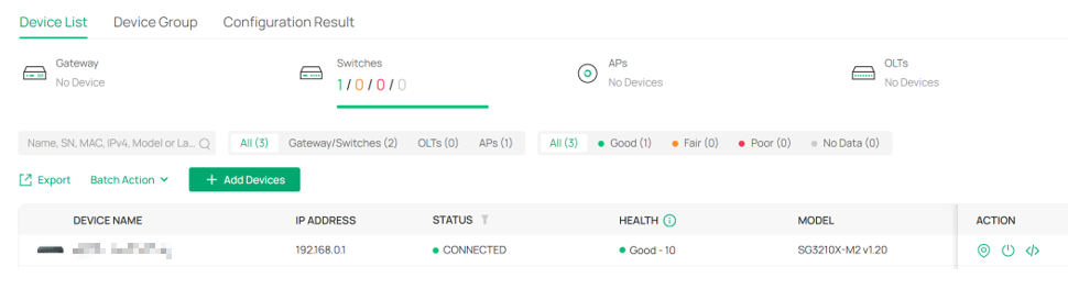
Step 1. Adopt the switch on Omada Controller.
First, adopt the switches which are directly connected to the IP phones.
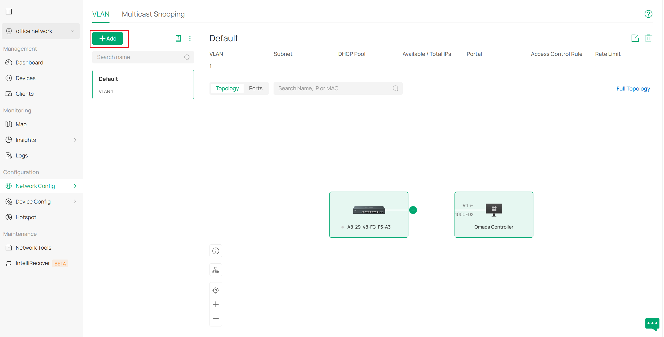
Step 2. Create 802.1Q VLAN for the use of voice VLAN.
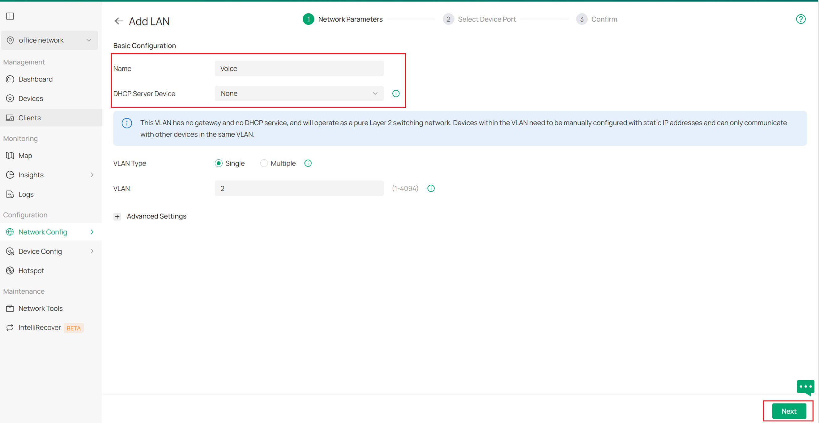
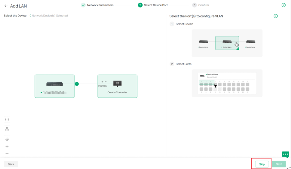
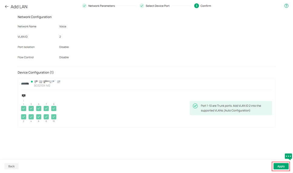
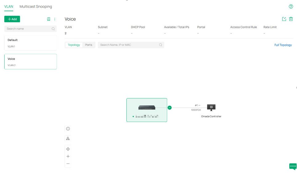
To assign a VLAN as voice VLAN, we need to create an 802.1Q VLAN first. Go to Network Config > Network Settings > LAN > VLAN, click Add, create a new VLAN, you can choose DHCP Server Device according to the actual stage. Here we only adopted a switch to show the configuration, DHCP service is not needed in later chapter, so we will set it as None. For other parameters just keep default or configure as you need. Then we follow the hint and tip to go through the VLAN creation step.
Step 3. Set the Voice VLAN untagged for the designated port
Now we are going to set VLAN 2, as is to be the Voice VLAN, untagged on the designated port to keep voice VLAN running as expected.
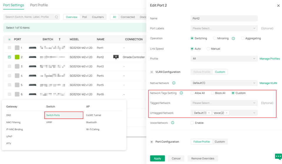
Go to Device Config > Switch > Switch Port, and select port 1, which is assumed to be the port for voice traffic. Then changing its Network Tags Setting to be custom so that we can move Voice(2) from the tagged network to the untagged network, as the picture shows.
Step 4. Configure OUI Profile Group
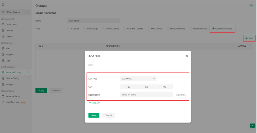
OUI Profile Group is a group containing OUI information for voice transmission. To set up an OUI Profile Group. Go to Network Config > Profile > Groups, then click Create New Group to keep up.
Next, name the group and select its type to be OUI Profile group. Then click +Add to add OUI you are getting on. Description is free for editing.
OUI profile is well done then.
Step 5. Configure OUI-based VLAN to raise the priority of voice traffic.
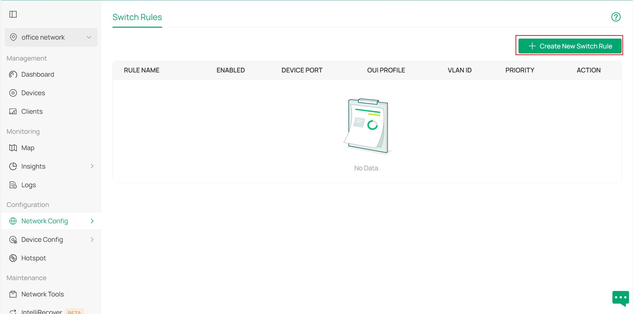
After created the voice VLAN 2, we are ready to go to configure OUI Based VLAN to optimize the transmission of voice traffic. It’s under Network Config > Transmission > OUI Based VLAN. After entering, we click the Create New Switch Rule button to continue.
Then we configure the parameters in our new rule configuration page according to needs. As an example, here we set the rule name, enable the rule and set port 1 of our switch where an IP phone is connected and where the rule will take effect.
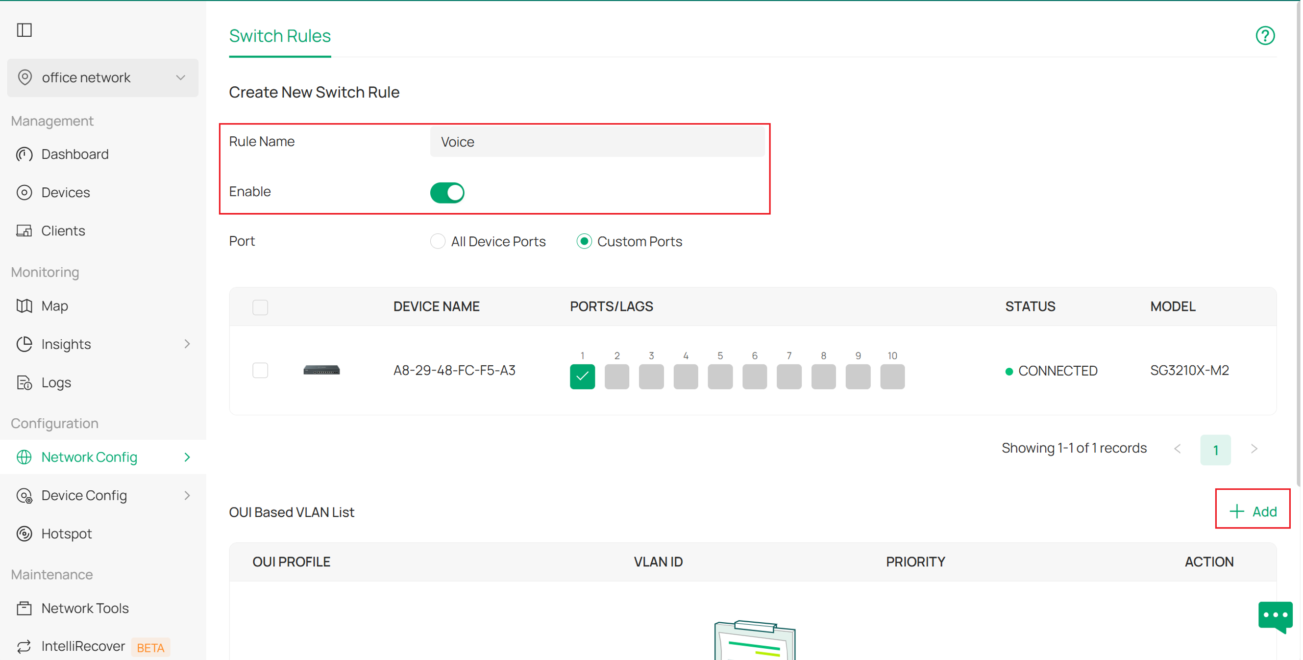
Next, click +Add at the right side of the screen to add an OUI-Based VLAN. This is where we bind the VLAN and OUI profile, which was created in the previous steps.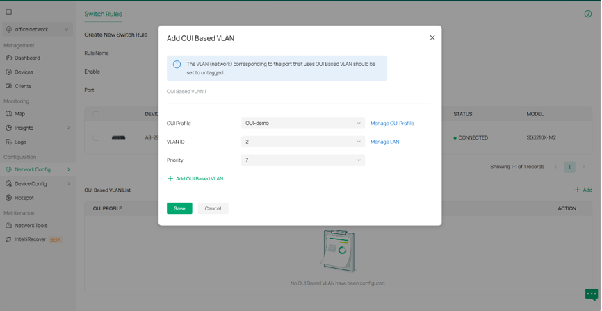
With proper Switch QoS configured How to Configure Switch QoS in Controller Mode | Omada Network Support. We select our OUI profile that was just created and VLAN 2, as it is going to be the Voice VLAN, and raise its priority to 7, which means the highest priority, so that traffic on this VLAN on the designated ports will be carried first.
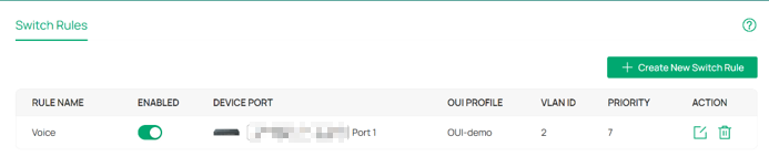
After applying and confirming, we are all set and done.
Managed under standalone mode
This section describes how to realize Voice VLAN configuration with GUI of standalone mode.
Step 1. Create a 802.1Q VLAN for the use of voice VLAN.
When managing under standalone mode, adoption is not needed so we start from creating VLAN.
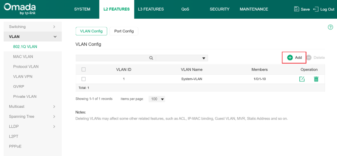
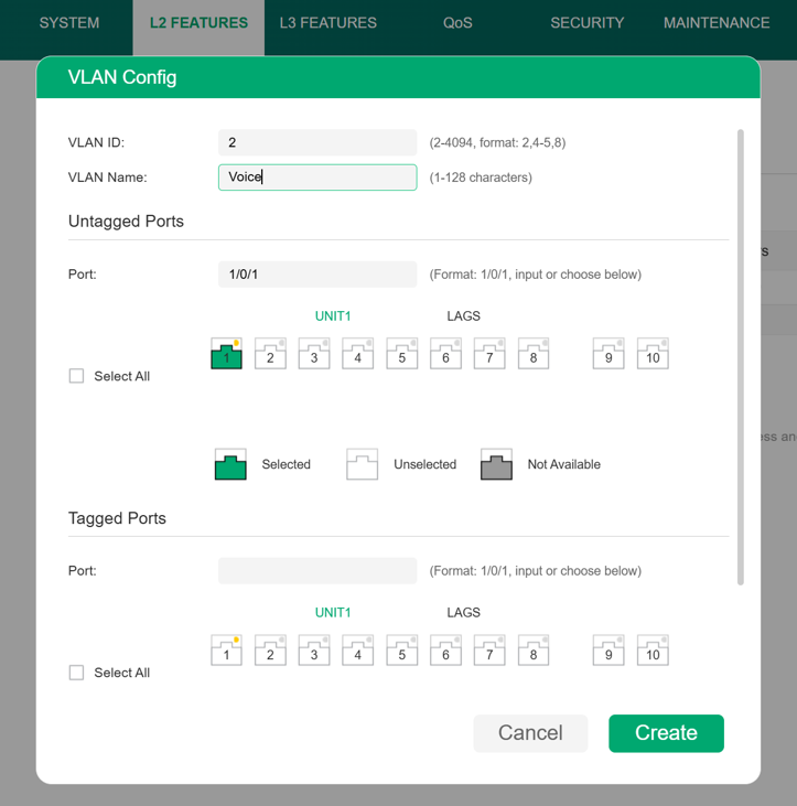
Go to L2 FEATURE > VLAN >802.1Q VLAN > VLAN Config. Then click +Add to establish a new VLAN. We will use port 1 as an example later, so we include it in VLAN 2.
Step 2. Configure OUI information.
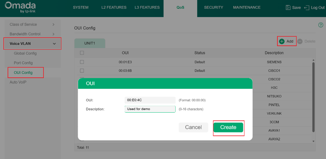
Go to QoS > Voice VLAN > OUI Config to specify the OUI information for your voice device. Click +Add on the right side to generate a new OUI profile. Click Create when you have it done.
Step 3. Enable Voice VLAN.
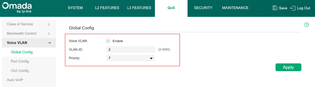
Go to the Global configuration of the voice VLAN column, it’s under QoS > Voice VLAN > Global Config. Enable this feature globally. Specify which 802.1Q VLAN is going to be the voice VLAN and its priority.
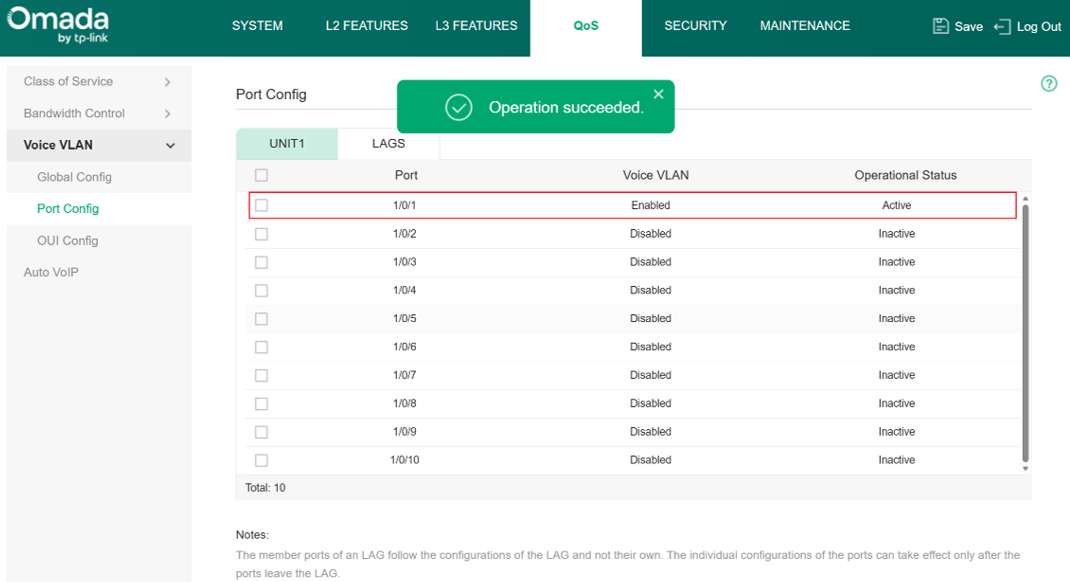
Finally, move to the Port config section under Voice VLAN to specify the ports where this feature will take effect. Change their status to enable. When the hint “Operation succeeded” pops up, you are good to go.
Verification
The configuration of Voice VLAN has finished and it should be working normally now. If you are interested, you can follow the steps below to validate:
We have added the OUI 00:E0:4C to the OUI table, so now we use the device with this OUI to send packets and validate if Voice VLAN is taking effect.
Currently, all the ports’ native VLANs are VLAN1, which means the packets should be captured without VLAN tags, but if the Voice VLAN is taking effect, the packets from this device will be tagged with VLAN 2 and 802.1p priority 7.
Voice VLAN is now enabled on port 1, so connect the device to port 1 and send normal IPv4 unicast packets, then use port mirroring to capture.
Results like below, from the screenshot, you can see that this packet’s source MAC address matches the OUI we have just set, and it has a VLAN tag with 802.1p priority 7 and VLAN ID 2, same as the parameters we have configured for Voice VLAN, which means the Voice VLAN is working.
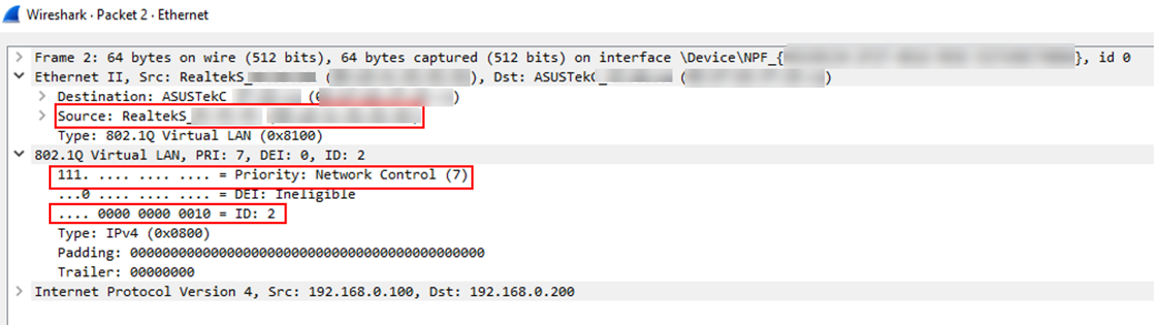
Please note that network adapters on Windows may discard the 802.1Q VLAN header, so if you find that the packets you captured are untagged, please check if your network adapter captures the VLAN tags normally by sending some tagged packets or monitor the traffic in other VLANs.
Conclusion
Till now we have finished introducing the configuration of Voice VLAN on Omada switches through Omada Controller and provided simple verification. If there’s still a problem, please contact TP-Link Technical Support.
To learn more about each function and configuration, please visit Support Home to download or check the manual for your product.
