


Contents
Support for Offline Device Display
Device Information Display on Hover
Additional Features in the Topology Display
Introduction
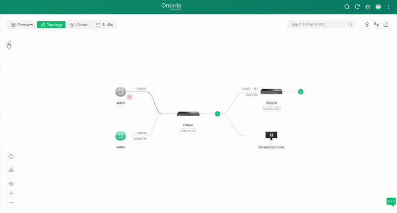
The topology display is a visual feature that provides users with a clear, real-time overview of how devices in the network are connected. It illustrates the topological relationships between routers, switches, access points, and clients, helping administrators quickly understand the structure of their network. By presenting these connections in an intuitive diagram, the topology display makes it easier to monitor device status, identify potential issues, and manage the overall network more effectively.
Requirements
- Omada Controller Version 6.0 or Higher
- Devices Adopted to Omada Controller
The new features in Omada Network V6.0’s Topology Display are roughly as follows:
Support for Offline Device Display
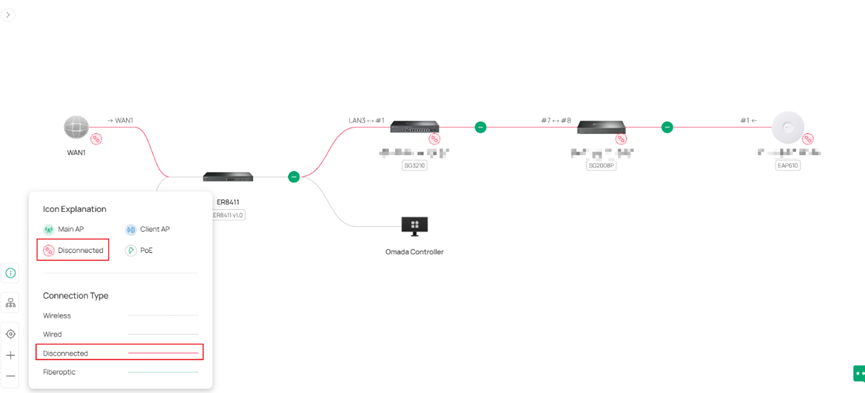
Navigate to: Site View>Dashboard>Topology to view the connected and disconnected devices in the topology map.
Note: When a device or WAN link is disconnected from the controller, it will reflect on the Topology Map with a red connection line and a broken chain link icon.
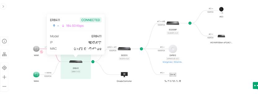
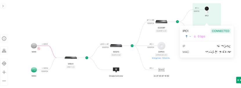
Device Information Display on Hover
When hovering over a device, key details such as its name, IP address, model, and status are displayed for quick reference. For third-party devices, the hover panel shows LLDP information like system name, IP Address info, and MAC address to help visualize network links.
To get device information in the hover view, you would navigate to: Site View>Dashboard>Topology>Hover over your desired device to view its information.
Right Panel
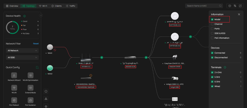
The right panel now lets you easily filter which devices and device information appear in the topology view. You can choose to show or hide certain device information and quickly toggle between viewing connected or disconnected devices, making it simpler to focus on the parts of the network that matter most.
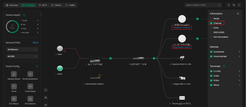
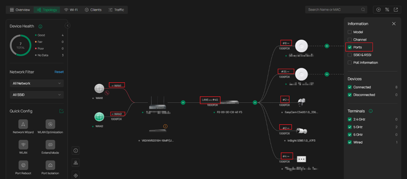
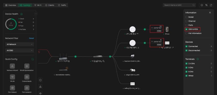
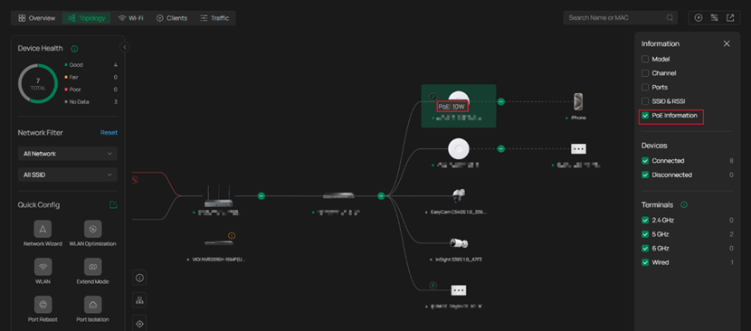
To access the right panel display, you would navigate to the Site View>Dashboard>Topology>Filter Icon. The Omada Network v6 Topology Map includes several filter options that help you quickly narrow down what you are looking at within your network. The Model filter lets you display only devices of a specific hardware type so you can focus on certain gateways, switches, or access points without visual clutter. The Channel filter highlights access points based on their operating channels, making it easier to spot channel overlap or RF congestion when reviewing wireless performance. The Ports filter allows you to view switch port status and activity so you can trace uplinks, downlinks, and active connections at a glance. The SSID&RSSI filter isolates client connections per SSID and displays signal strength information to help you check client distribution and identify weak-signal or roaming issues. Lastly, the PoE Information filter shows which ports are providing power and how much PoE budget is being consumed, allowing you to quickly verify powered devices and detect any power-related issues across your switches. Here are some examples.
Filter by Model:
Filter by Channel:
Filter by Ports:
Filter by SSID&RSSI:
Filter by PoE Information:
Left Panel
The new left panel (Quick Config panel) provides a clear overview of your entire network topology, helping you quickly understand how all devices are connected. It also lets you filter devices by VLAN or SSID and highlight specific ones within the topology for easier analysis and troubleshooting.
In addition, the Quick Config panel enables you to adjust network settings without leaving the topology view. You can use the Edit option to modify configuration items displayed in the panel, or launch the Network Wizard to perform a fast setup and initial configuration of your network. The panel also includes helpful tools such as WLAN Optimization and other quick configuration features, allowing you to make real-time adjustments, streamline deployments, and optimize performance directly within the topology page.
To access the left panel in the topology view, you would need to navigate to: Site View>Topology> Then click the “>” button under Overview.
Addtional Feature in the Topology Display
The topology view offers a range of additional tools and interactive elements designed to help you visualize, manage, and analyze your network more efficiently.
Isolated/Preconfigured Device Cards
When devices are in the Isolated or Preconfigured state, they appear in a dedicated card on the right side of the left panel. These cards show all devices in those states and can be expanded or collapsed as needed.
Top-Left Device Statistics Card
The Device Statistics Card in the upper-left corner provides an overview of the total number of devices within the current site, as well as how many are connected or disconnected.
Search Function
The search box in the top-right corner allows both precise and fuzzy searches across all nodes in the topology, making it easy to locate specific devices.
Traffic Function
Clicking the Traffic button in the top-right corner displays the real-time traffic rate of each node. Clicking it again will remove the traffic overlay from the topology map.
Export Function
You can export the topology map for recordkeeping, reporting, or sharing purposes.
Vertical/Horizontal View and Zoom Controls
Buttons next to the Quick Config panel in the lower-left corner allow you to switch the topology layout between vertical and horizontal orientations. You can also zoom in, zoom out, or fit the topology to your current screen view.
Change Root Node
If a gateway has not been adopted in the site, you can manually set a switch (SW), OLT, or third-party device as the topology’s root node. If only access points (APs) are adopted, an AP can also be specified as the root node.
Conclusion
In summary, while the topology display remains a visualization tool without configuration capabilities, the enhancements introduced in version 6.0 significantly improve its utility. Administrators can now view offline devices and their connection relationships, access key device and LLDP information through hover interactions, and filter devices displayed by status, VLAN, or SSID. These improvements provide a more comprehensive and flexible view of the network, enabling faster identification of issues and more effective oversight of the entire infrastructure.
Get to know more details of each function and configuration please go to Download Center to download the manual of your product.
QA
Q1: What is the purpose of the Topology Display in Omada Controller V6.0?
A1: The topology display provides a real-time visual overview of how all network devices are connected — including routers, switches, access points, and clients. It helps administrators quickly identify relationships, monitor device status, and manage the network more effectively.
Q2: What version of the Omada Controller is required for the new topology features?
A2: You’ll need Omada Controller Version 6.0 or higher, and all devices must be adopted to the controller to display properly in the topology view.
Q3: What does the new “Offline Device Display” feature do?
A3: If a device unexpectedly disconnects, the topology display shows its previous connection path so you can still visualize where it was linked before going offline. You can find this under Site View > Dashboard > Topology. Disconnected devices appear with red connection lines and a broken chain link icon.
Q4: How can I identify disconnected devices in the topology?
A4: Disconnected or offline devices are represented by red lines and a broken chain link icon on the topology map. This allows you to quickly see which devices have lost connection to the controller.
Q5: What information is displayed when hovering over a device?
A5: When you hover over an Omada device, the display shows its model, IP address, MAC address, connection status, and data transmission speeds. For third-party devices, hover details display LLDP information such as system name, IP address, and MAC address.
Q6: How do I view device information using the hover feature?
A6: Navigate to Site View > Dashboard > Topology, then hover over any device in the topology map to view its key details.
Q7: What is the purpose of the new right panel in Topology View?
A7: The right panel lets users filter displayed devices and information types. You can show or hide details such as Model, Channel, Ports, SSID & RSSI, PoE Information, and filter between Connected and Disconnected devices. Access it via Site View > Dashboard > Topology > Filter Icon.
Q8: What does the “Filter” button on the right side do?
A8: Clicking the “Filter” icon opens a panel where you can choose which devices and details to display on the topology map. For instance, you can toggle SSID and RSSI information for all wireless devices or use the Network Filter panel on the left to highlight devices associated with a specific SSID, helping you focus on particular parts of your network.
Q9: What new functionality does the left panel introduce?
A9: The new left panel gives you a full network overview and allows you to filter or highlight devices by VLAN or SSID. It also includes a Quick Configuration page, where you can make instant adjustments — such as WLAN optimization — without leaving the topology view.
Q10: How do I open the new left panel?
A10: Go to Site View > Topology, then click the “>” button under Overview to expand the left panel.
Q11: Can I make configuration changes directly in the topology display?
A11: No, the topology display is primarily a visualization tool. However, Version 6.0’s Quick Configuration feature in the left panel allows limited changes like WLAN optimization without leaving the view.
Q12: How can I access more detailed instructions or manuals?
A12: For detailed information about configuration and advanced features, visit the TP-Link Download Center and download the manual for your product model.
Q13: What should I do if I fail to connect to the internet?
A13: Check if the network cable is properly connected. If the issue persists, verify that the device is adopted and online in the Omada Controller topology view, and ensure that all uplink devices are powered and connected.
