Contents
Typical BGP Application Scenarios
Introduction
BGP Overview
BGP (Border Gateway Protocol), is a routing protocol used for exchanging routing information between autonomous systems. It is a routing protocol that runs on top of TCP.
BGP can be divided into IBGP (Internal Border Gateway Protocol) and EBGP (External Border Gateway Protocol). IBGP is used for peers within an AS to pass routes learned from outside the AS, ensuring that all routers within the AS share all external BGP routes. EBGP is used for peers between different ASs to pass routes, enabling network interconnection with the internet. There are two important roles in BGP: Speaker and Peer. BGP Speaker is the routing device that sends BGP messages, and the two Speakers exchanging BGP messages are called Peers.
There are five core message interactions between BGP peers: Open, Update, Notification, Keepalive, and Route-refresh.
Open message: The first BGP message sent after a TCP connection is established. It is used to establish a BGP peer.
Update message: The routing information exchanged between peers. It consists of advertising reachable routes and revoking unreachable routes.
Notification message: When a peer detects an error, it will send a Notification message to its remote peer and terminate the BGP connection.
Keepalive message: After establishing a connection, the peer immediately sends a keepalive message, then periodically sends additional messages to maintain the validity of the connection.
Route-refresh message: A peer sends a message to request its remote peer to resend all reachable routing information.
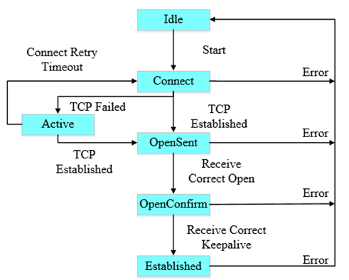
There are six states between BGP Peers: Idle, Connect, Active, OpenSent, OpenConfirm, and Established.
Typical BGP Application Scenarios
Omada L3 switches feature a complete BGP protocol stack with high port density and switching capacity. The BGP route convergence speed and data forwarding performance are typically higher than those of traditional routers. The application of L3 switches in BGP essentially offloads the core routing functions traditionally performed by routers to the aggregation layer of the data center, meeting the needs of data centers and large enterprise networks.
BGP is typically used in large-scale, complex campus networks requiring fine-grained traffic control. BGP is also suitable for campus networks when the campus networks exhibit the following characteristics:
- Multiple ISP exits
- Large-scale, modular networking
- Active-active data centers
- Dedicated lines with cloud service providers
- Routing Exchange Within and Between ISPs
In ISP networks, BGP is the core protocol for handling large-scale routing information. ISP networks typically contain multiple autonomous systems, and BGP ensures that these autonomous systems can correctly exchange routing information. Meanwhile, ISP networks also need to use BGP to exchange routes to guarantee global internet access services.
- Data Center Interconnection
Data centers typically contain a large number of servers and storage devices, requiring efficient, reliable, and stable connections. BGP enables route exchange across data centers or cloud service providers, achieving interconnection. Meanwhile, BGP's route aggregation and incremental update mechanisms help reduce the complexity and update frequency of routing tables.
- Large-Scale Enterprise Networks with Multi-Exits
Large enterprises typically use multi-exit networks (multiple ISPs). With the BGP protocol, enterprises can connect their branch networks into a unified network architecture. At the same time, with BGP routing policies, enterprise networks can achieve traffic load balancing, optimization, and redundancy, and select the best exit path.
Requirement
- Omada Pro L3 Switch
Configuration
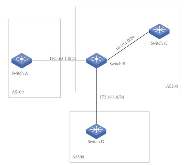
Currently, only Omada Pro L3 switches support BGP, and only CLI configuration is supported. Taking the following topology as an example: AS100, AS200, and AS300 are three autonomous systems, configured with EBGP+IBGP+IGP.
Switch A establishes an EBGP neighbor relationship with Switch B, and Switch B establishes an EBGP neighbor relationship with Switch D. Because Switch A and Switch D are not directly connected, even if their interfaces are on the same network segment, the default EBGP hop limit of 1 prevents them from forming a direct EBGP neighbor relationship. The BGP hop count can be modified using CLI commands.
Switch B establishes OSPF and IBGP neighbor relationships with Switch C. After Switch B and Switch C establish an IBGP neighbor relationship, Switch B can advertise routes learned from external sources to Switch C. Routes learned by Switch C from Switch B will not be advertised to IBGP neighbors. This is an important BGP loop-prevention mechanism that effectively prevents black-hole routing in complex topologies, especially when there are three or more IBGP neighbors.
Configuration Steps:
Configure the interface for each switch as follows:
|
Switch A |
192.168.1.1/24 |
|
192.168.20.1/24 |
|
|
Switch B |
192.168.1.2/24 |
|
172.16.1.1/24 |
|
|
10.10.1.1/24 |
|
|
Switch C |
10.10.1.2/24 |
|
10.10.30.1/24 |
|
|
Switch D |
172.16.1.2/24 |
|
172.16.40.1/24 |
Configuration for IGP
Within AS200, configure IGP (e.g., OSPF). Configure OSPF between Switch B and Switch C to advertise routing information within the autonomous system.
Create an OSPF area 0.0.0.0 on Switch B with network 10.10.1.0/24.
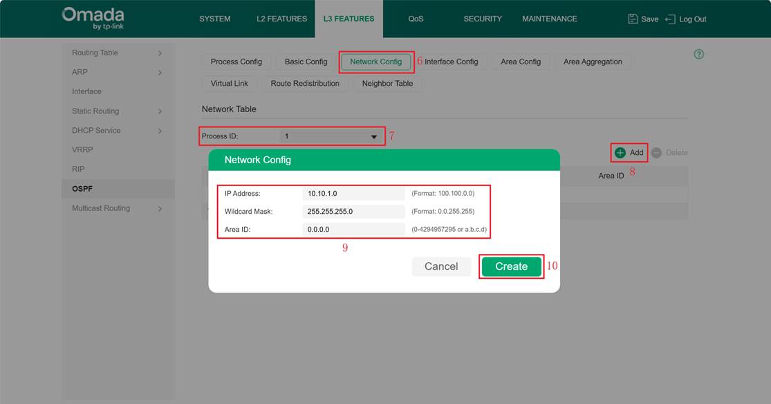
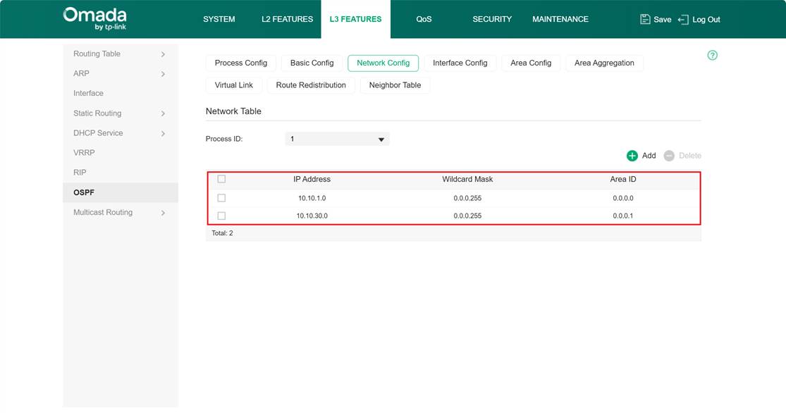
Create OSPF areas 0.0.0.0 and 0.0.0.1 on Switch C, with network 10.10.1.0/24 and 10.10.30.0/24.
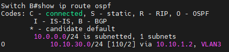
Check the routing table of Switch B. You can see it has correctly learned the route 10.10.30.0/24 via OSPF.
Configuration for BGP
Configure BGP on Switch A:
Step 1. Enter config mode and set the local AS number.
Switch A#config
Switch A(config)#router bgp 100
Step 2. It is recommended to configure BGP router-id. By default, the largest IP will be used as the router-id.
Switch A(config-router)#bgp router-id 192.168.1.1
Switch A(config-router)#clear ip bgp all
Step 3. Configure the neighbor’s IP and the remote peer’s AS number (Switch B)
Switch A(config-router)#neighbor 192.168.1.2 remote-as 200
Step 4. Configure advertise routes, such as advertising local routes over the network or redirecting the routes of other protocols (e.g., static routes/directly connected routes/OSPF/RIP/IS-IS). The following configuration advertises the local route 192.168.20.0/24.
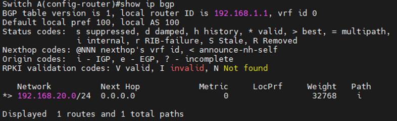
Switch A(config-router)#network 192.168.20.0 mask 255.255.255.0
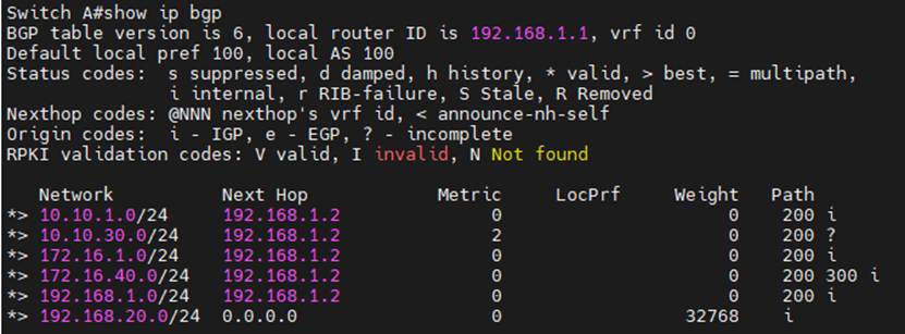
Check Switch A’s BGP advertise routes.
Configure BGP on Switch D.
Switch D#config
Switch D(config)#router bgp 300
Switch D(config-router)#bgp router-id 172.16.1.2
Switch D(config-router)#clear ip bgp all
Switch D(config-router)#neighbor 192.172.16.1 remote-as 200
Switch D(config-router)#network 172.16.40.0 mask 255.255.255.0
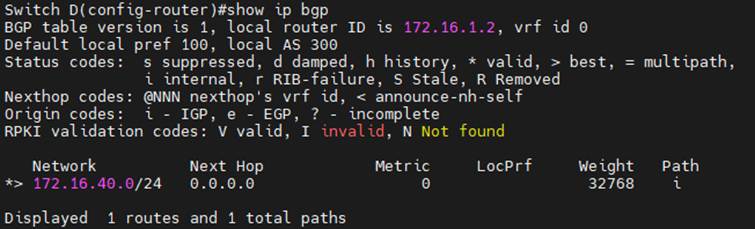
Check Switch D’s BGP advertise routes.
Configure BGP on Switch B. Establish EBGP connections with both Switch A and Switch C, and establish an IBGP connection only with Switch C. Routing information learned from external sources is advertised to IBGP neighbors within the autonomous system via IBGP. Switch B advertises routes for OSPF instance 1 by redirecting OSPF protocol routes.
Switch B#config
Switch B(config)#router bgp 200
Switch B(config-router)#bgp router-id 192.168.1.2
Switch B(config-router)#neighbor 192.168.1.1 remote-as 100
Switch B(config-router)#neighbor 172.16.1.2 remote-as 300
Switch B(config-router)#neighbor 10.10.1.2 remote-as 200
Switch B(config-router)#redistribute ospf 1
Switch B(config-router)#network 192.168.1.0 mask 255.255.255.0
Switch B(config-router)#network 172.16.1.0 mask 255.255.255.0
Switch B(config-router)#network 10.10.1.0 mask 255.255.255.0
Configure BGP on Switch C and establish an IBGP connection with Switch B
Switch C#config
Switch C(config)#router bgp 200
Switch C(config-router)#bgp router-id 10.10.1.2
Switch C(config-router)#neighbor 10.10.1.2 remote-as 200
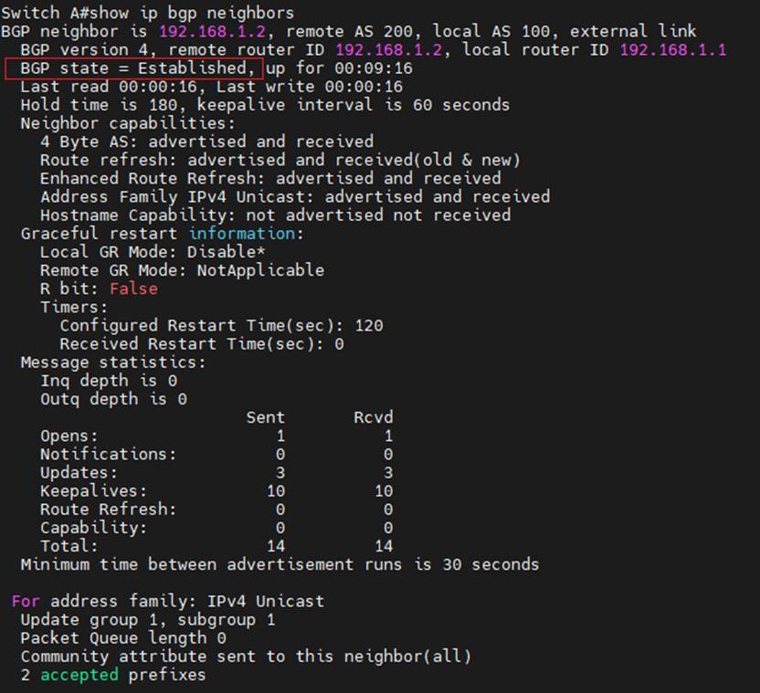
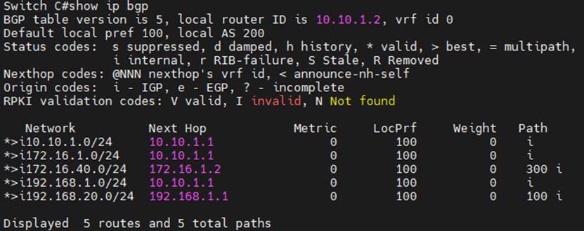
Check the BGP connections, local router-id, remote router-id, and advertise routes.
Switch A:
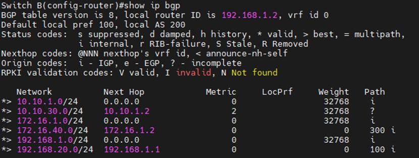
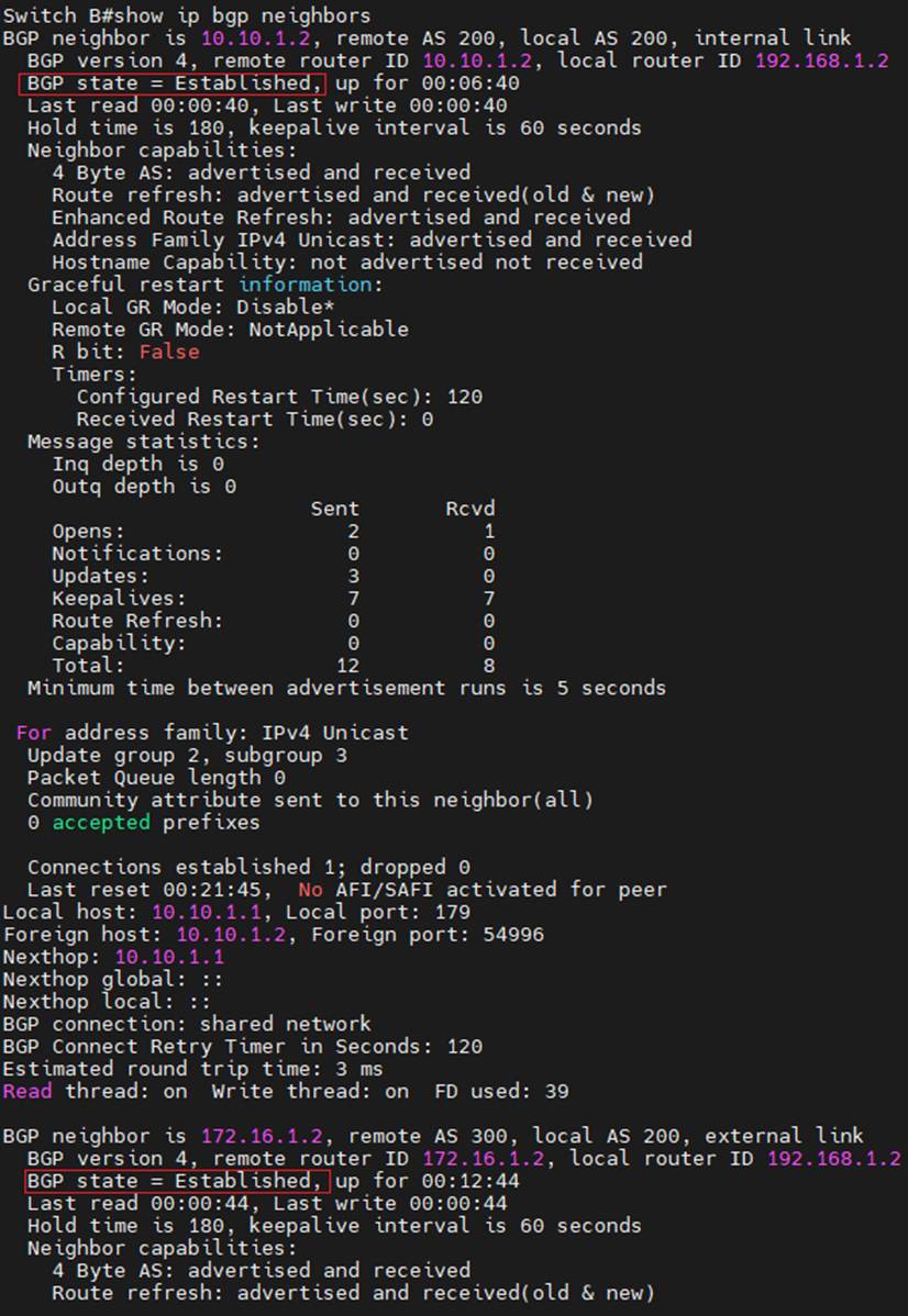
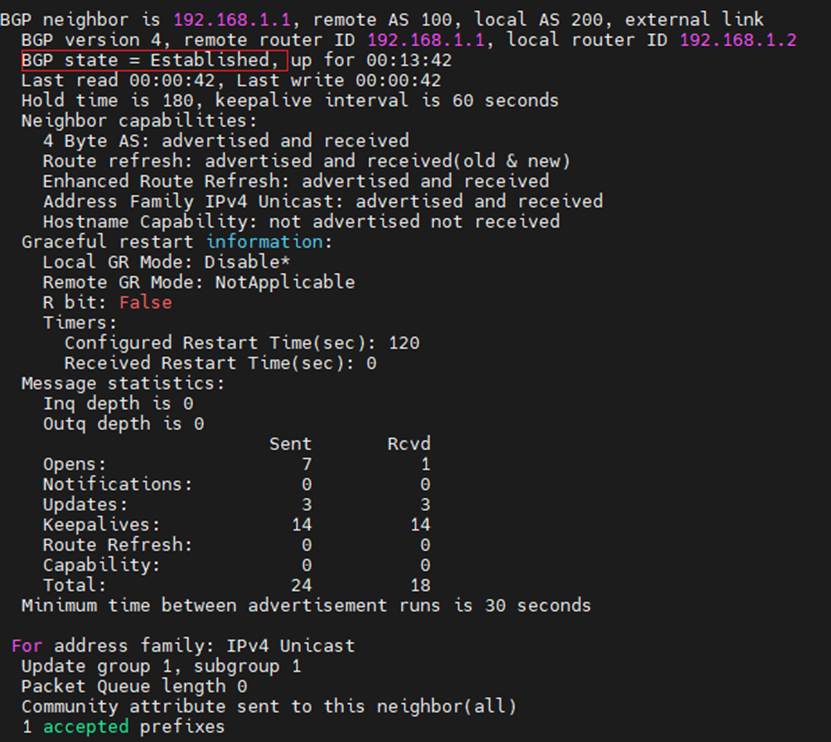
Switch B:
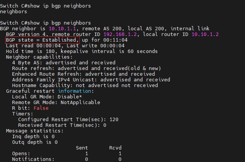
Switch C:
Switch D:
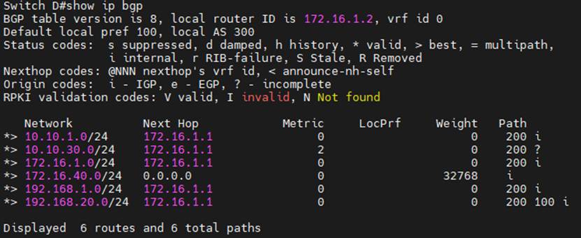
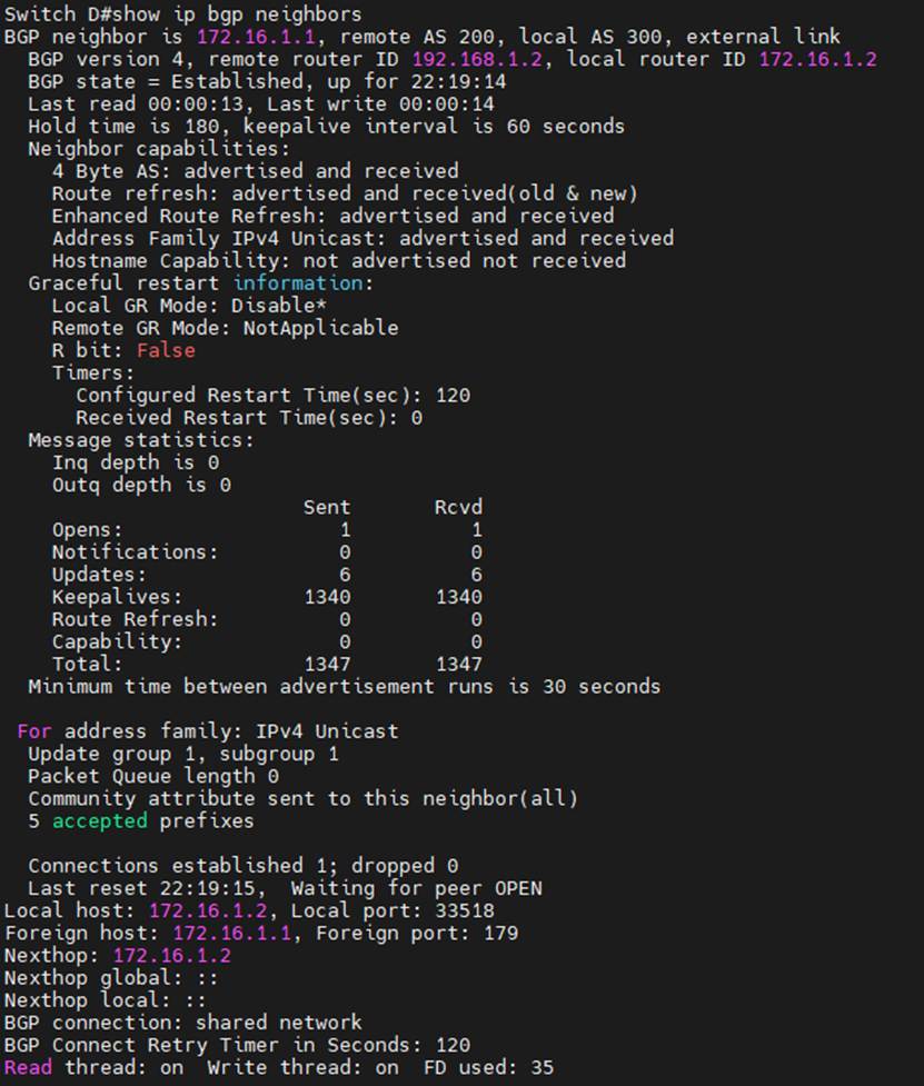
Conclusion
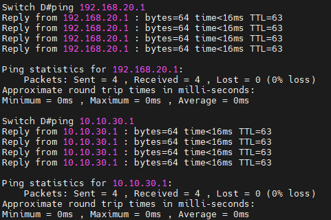
As shown in the diagram above, EBGP connections have been successfully established between Switch A and Switch B and between Switch B and Switch D. An IBGP connection has been successfully established between Switch B and Switch C. Pinging the interface IP addresses of Switch A (192.168.20.1/24) and Switch C (10.10.30.1/24) from Switch D is successful.