


How to Design and Deploy Your Network with Omada Design Hub


Contents
Objective
This article will guide you step by step through the process of designing and deploying your network using Omada Design Hub.
Requirements
The following requirements must be met to access and use Omada Design Hub:
- Internet Access – Required to visit and use the Omada Design Hub at https://design.tplinkcloud.com/
- TP-Link ID Account – You must have a TP-Link ID to sign in to the Omada Design Hub. If you don’t have one, you need to create it first.
Introduction
Omada Design Hub provides a visual, AI-powered platform that helps you plan, design, and deploy your network with ease. Whether you’re setting up a small office or a multi-floor enterprise, Omada Design Hub allows you to create accurate floor plans, simulate wireless coverage, organize cabling, and generate detailed deployment reports—all in one intuitive interface.
This step-by-step guide will take a two-story office for example to help you design and deploy your network using Omada Design Hub.
Configuration
Access Omada Design Hub
To access Omada Design Hub, visit https://design.tplinkcloud.com/. You will need a TP-Link ID to sign in. If you do not have an account, create one first.
Note: To create a TP-Link ID: Visit https://community.tp-link.com/en/register and enter all the required information. After clicking “Register,” you will receive an activation email. Click the link in the email to activate your TP-Link ID. Once activated, you will be able to login to Omada Design Hub.
Create a New Project
After logging in, follow these steps to create a new project:
Step 1: On the first page (Project List), click +Add to create a new project..
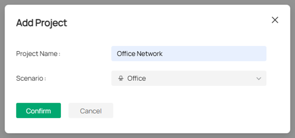
Step 2: Specify a project name and select an appropriate scenario, such as “Office Network” as the project name and “Office” as the scenario. Then Click Confirm.
Note: If the predefined scenarios do not fit your need, click + Add New Scenario to customize your own scenario.
Create a New Floor
After creating your project, you will be automatically redirected to the Floor Plan page. To create a new floor, follow the steps below:
Step 1: Click Upload Floor Plan. Multiple file formats are supported; however, only one file can be uploaded at a time.
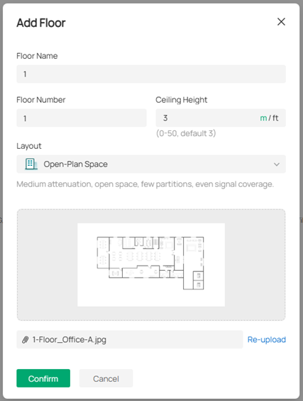
Step 2: Specify the floor name, floor number, and ceiling height. Select the layout that best matches your environment to ensure a more accurate simulation. Click Confirm to proceed.
Note:
- You can switch the unit for the ceiling height between meter and feet.
- You can click the image to preview it and re-upload another file if you want to change it.
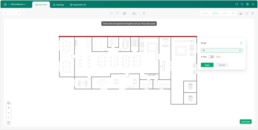
Step 3: Set the scale for your map. Left-click on the starting point to draw a line, then left-click again to mark the endpoint. Enter the actual length of the line, and click Apply to confirm.
Note:
- Make sure the floor plan scale reflect the actual environment, as it impacts wall simulation, cable length, and wireless coverage.
- To reset the scale, click the scale icon in the bottom right.
Draw Walls
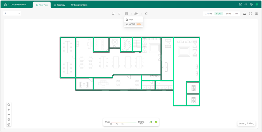
Before deploying devices, draw the walls on the floor plan to indicate obstructions.
Step 1: Click AI Wall to draw walls. This smart tool helps significantly reduce the time required for the drawing process.
Step 2: Modify the walls manually. You can further add new walls, move, split, or delete the existing walls, and change the wall types.
Deploy Devices
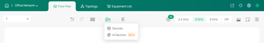
With your layout prepared, you can now begin deploying devices. Similarly, start with the AI tool to simplify the process.
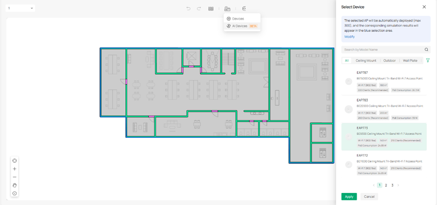
Step 1: Click AI Devices and select an AP model. Click Apply.
Note: Only EAPs are currently available for AI Devices.
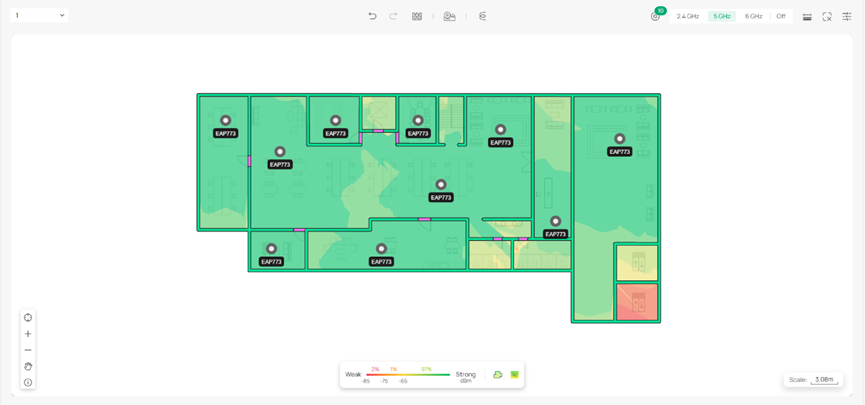
Step 2: Click a specific band to view the Wi-Fi coverage and adjust the AP deployment.
Note: Hover your mouse over an AP to visualize its Wi-Fi coverage on the heat map.
Step 3: Add gateways, switches or extra APs manually based on your actual need. Click Devices and select a model. Place the device to a desired location.
Deploy Cables
- In a single floor
After properly placing the devices, deploy cables to connect them on the current floor.
Step1: Click Cable and Cable Tray to design a structured cabling system that routes and organizes cables efficiently according to your actual environment.
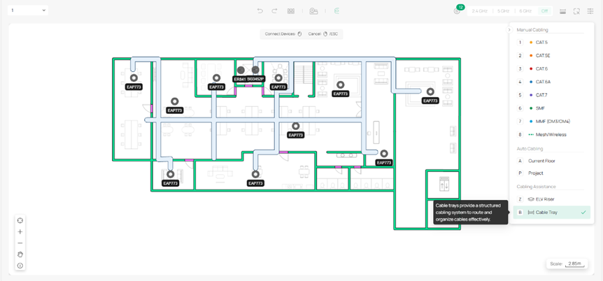
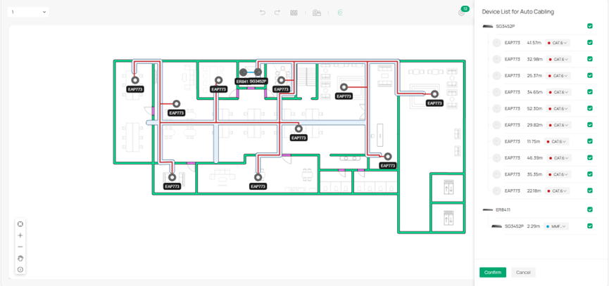
Step 2: Use Auto Cabling to quickly deploy connections. Adjust the cabling results as needed, then click Confirm.
Step 3: Adjust the cabling manually.
- Across multiple floors
Auto Cabling also supports multi-floor cabling within a project.
Step 1: Follow the same procedure described above to create the second floor.
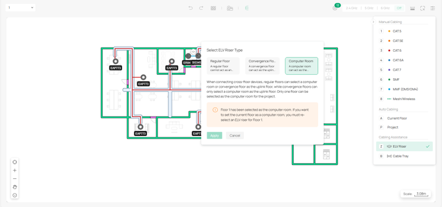
Step 2: Deploy an ELV riser on each floor and select the ELV riser type for the floor.
Note: Cross-floor devices need to be connected through ELV risers.
Step 3: Use Auto Cabling for the project and adjust the cables.
View Topology
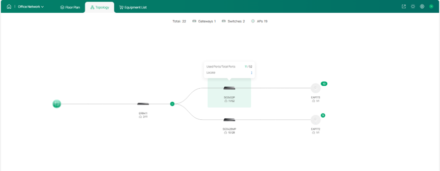
Click Topology at the top to view the network topology for the entire project. Hover over a specific device to check its port usage and locate the device.
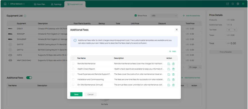
Check Equipment List and Fees
Step 1: Go to the Equipment List to view the deployed devices and their accessories. You can specify the quantity and unit price to calculate the total deployment cost.
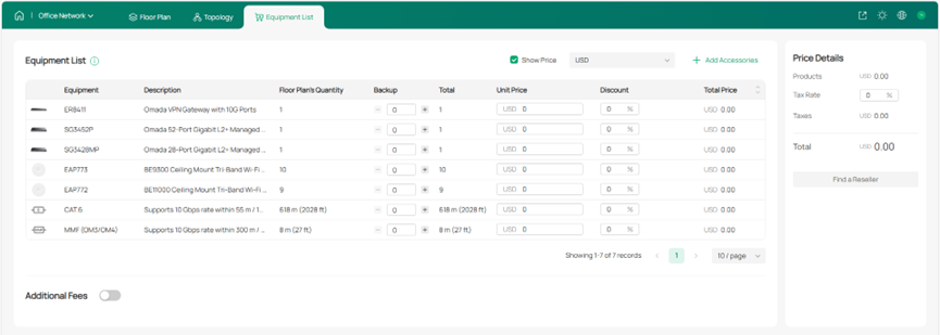
Step 2: You can also include additional fees as needed.
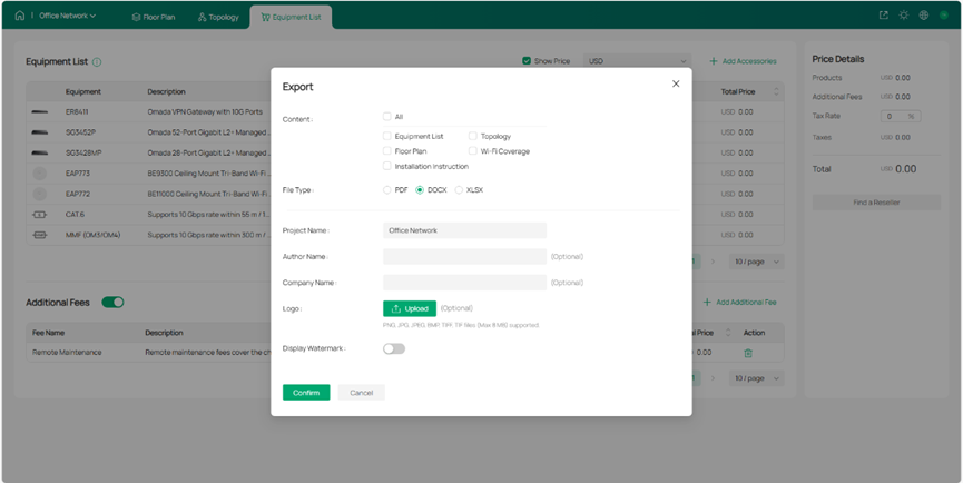
Export Network Design Report
Once you are satisfied with your network plan, you can export a report for reference during actual network deployment.
For detailed guidance and more information, refer to the user guide of Omada Design Hub.
Conclusion
Omada Design Hub makes network planning and deployment fast and intuitive. With AI-assisted device placement, multi-floor support, and structured cabling tools, you can visualize your network, optimize layout, and manage costs efficiently. The exported design report provides a practical reference for smooth and reliable network deployment.
Get to know more details of each function and configuration please go to Download Center to download the manual of your product.
FAQ
Question 1: Do I need a TP-Link ID to use Omada Design Hub?
Answer: Yes, a TP-Link ID is required to access Omada Design Hub. If you don’t have one, you can create an account for free.
Question 2: Can I design a multi-floor network in Omada Design Hub?
Answer: Yes, Omada Design Hub supports multi-floor projects. You can create multiple floors, deploy devices on each floor, and connect them through ELV risers using Auto Cabling for efficient vertical cabling.
Question 3: How can I calculate the cost of my network deployment?
Answer: Use the Equipment List to specify device quantities and unit prices. You can also add additional fees as needed. The system will automatically calculate the total deployment cost.
Question 4: Is Omada Design Hub a free tool?
Answer: Yes, Omada Design Hub is a free tool.
Question 5: What is included in the exported network design report?
Answer: The exported report includes the floor plan, device deployment, cabling layout, ELV riser connections, topology, and a detailed equipment list with quantities and costs. It serves as a comprehensive reference for actual network deployment and future maintenance.
