


Contents
Single-Floor Cable Drawing (Current Floor)
Multi-Floor Cable Drawing (Project)
Introduction
The Cable function in Omada Design Hub enables you to visualize and plan cable layouts within a building or across multiple floors. Proper cabling design is essential for ensuring a stable, efficient, and scalable network—affecting performance, reliability, PoE delivery, and future expansion. Clear cable paths also help teams coordinate on-site deployment and avoid installation issues.
To streamline this process, Omada Design Hub supports Auto Cabling, which automatically generates device-to-device cable connections based on recommended topology rules. This reduces manual workload while still allowing full customization and fine-tuning to match real-world building structures such as walls, cable trays, and ELV risers.
Requirements
- Omada Design Hub
- Floor plan(s)
Configuration
Single-Floor Cable Drawing (Current Floor)
We will start with a floor plan where walls and Omada devices (Omada Controller, Omada Gateway, Omada Switch, and Omada EAP) have already been placed.
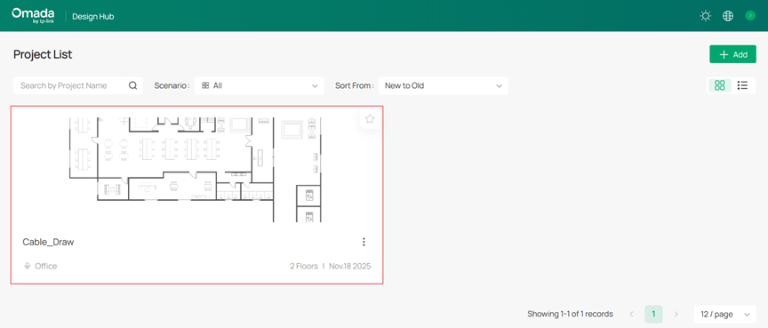
Step 1. Log in to Omada Design Hub and open your project.
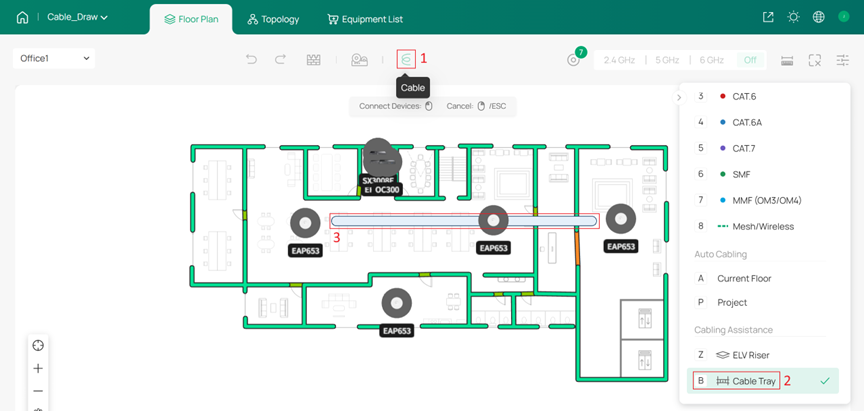
Step 2. On Floor Plan, using Cable icon > Cable Tray to draw cable trays.
Cable trays represent centralized cable routing channels and can also serve as guidance for Auto Cabling. It is recommended to configure them based on your actual building layout and wiring needs.
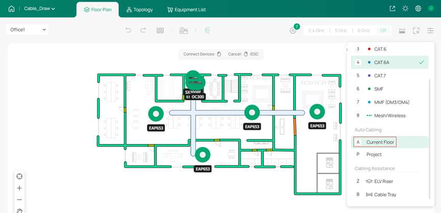
Step 3. (Optional) Use Auto Cabling, selecting Current Floor to automatically generate cable connections on this floor.
Note:
- Auto Cabling requires at least two types of devices in the topology.
- Auto Cabling will target the connection sequence: gateway > core switch > aggregation switch > access switch > EAP.
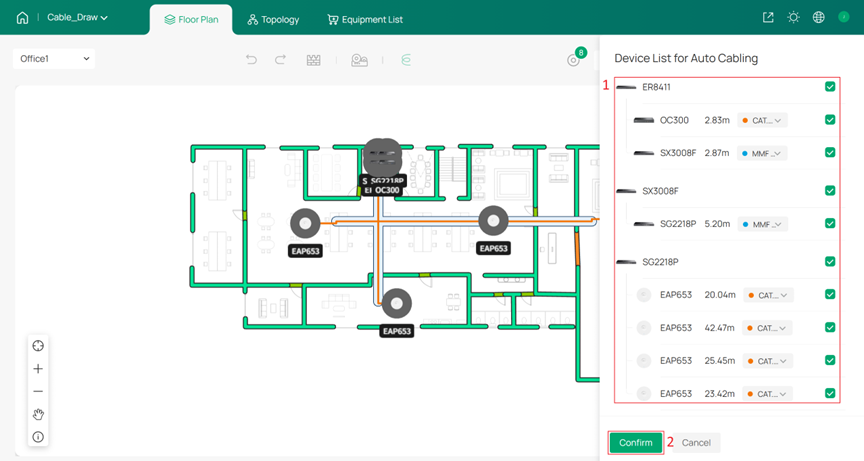
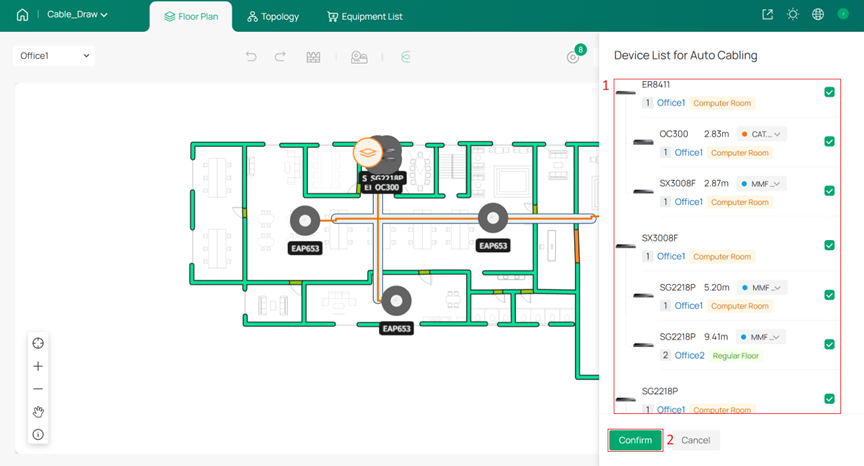
You can choose whether to enable Auto Cabling and specify the cable type used for each connection segment. Click Confirm to complete Auto Cabling.
Note: After clicking Confirm, all previously drawn cables will be overwritten.
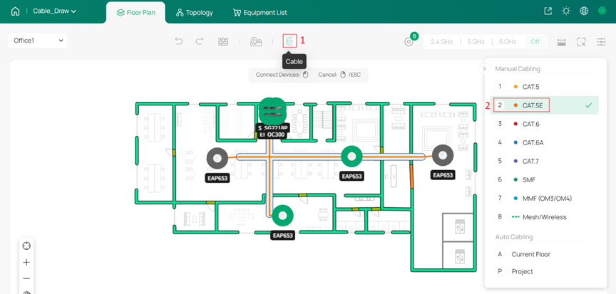
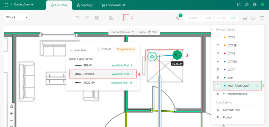
Step 4. Manually draw or fine-tune cable paths to better match your specific layout or design requirements.
Select a cable type and manually connect devices. Click any device to start drawing a cable, then click on a blank space to add a node, and finally click the target device to complete the connection.
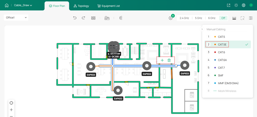
You can also use Add Node on existing cables to add turns, helping the cable paths better match your layout or design requirements. Or use Delete Cable to delete and redraw it.
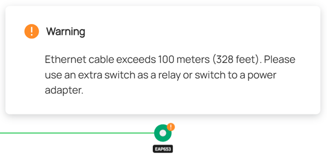
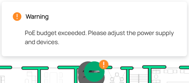
Common topology issues will be highlighted on devices.
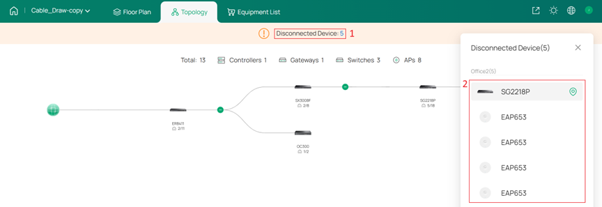
Step 5. On Topology, you can check that all devices are correctly connected and that the overall network structure.
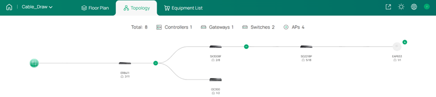
If there are any unconnected devices, you can quickly locate them.
Multi-Floor Cable Drawing (Project)
We will start with a project where walls, cable trays, and Omada devices (Omada Controller, Omada Gateway, Omada Switch, and Omada EAP) have already been placed.
You can refer Step 2. of Single-Floor Cable Drawing (Current Floor) to draw cable trays.
Step 1. Log in to Omada Design Hub and open your project.

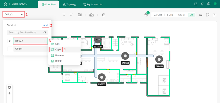
Step 2. Create a project containing multiple floors. You can add new floors using Add or Copy existing ones.
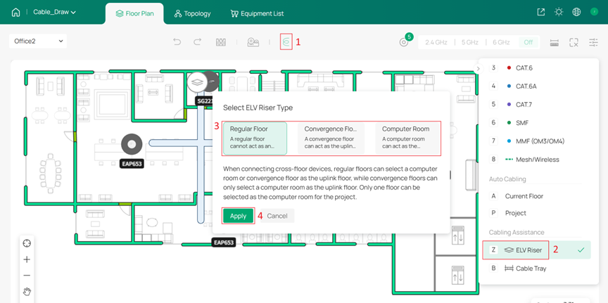
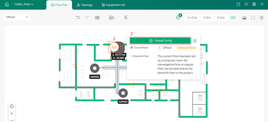
Step 3. On the Floor Plan, use the Cable icon > ELV Riser to configure the ELV risers for each floor.
ELV riser represents the pathways that connect different floors vertically. It is divided into three types:
- Computer Room: Acts as the top-level node (e.g., server room) and serves as the upstream for all floors. Only one floor can be designated as the Computer Room.
- Convergence Floor: An intermediate floor between the Computer Room and Regular Floors, used to aggregate connections from multiple Regular Floors.
- Regular Floor: The standard floor containing devices; can only act as a downstream floor to the Computer Room or Convergence Floor.
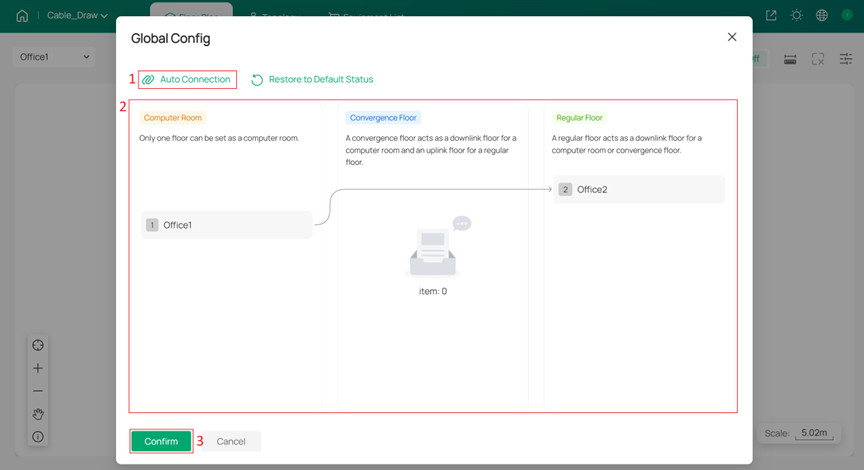
Step 4. Click any ELV Riser to enter Global Config and configure connections between floors.
You can use Auto Connection for automatic configuration or set the connections manually.
When manually adjusting cross-floor connections, it is recommended to maintain a reasonable number of network hierarchy levels.
- For small to medium-sized networks, such as a project with 4 Regular Floors, it is advisable to connect all floors directly to the Computer Room.
- For large-scale networks, such as a project with 20 Regular Floors, it is recommended to plan for 2 to 4 Convergence Floors and organize the structure following the order of Computer Room > Convergence Floor > Regular Floor.
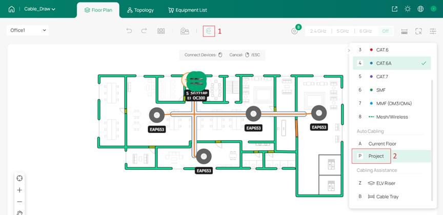
Step 5. (Optional) Use Auto Cabling, selecting Project to automatically generate cable connections.
Note:
- Auto Cabling requires at least two types of devices in the topology.
- Auto Cabling will target the connection sequence: gateway > core switch > aggregation switch > access switch > EAP.
- Cross-floor connections will refer to Global Config, automatically select the upstream floor and connect through ELV risers.
Note: After clicking Confirm, all previously drawn cables will be overwritten.
Step 6. Fine-tune cable paths and verify the topology according to Step 4. and Step 5. of Single-Floor Cable Drawing (Current Floor).
For cross-floor connections, you need to start from the downstream device, connect to the ELV Riser on its floor, and then select the upstream device.
Conclusion
This article introduced how to draw cables in the Omada Design Hub, both for a single floor and across multiple floors. By combining Auto Cabling with manual refinement, you can efficiently produce realistic cable layouts and confirm complete network topologies within the design environment.
Get to know more details of each function and configuration please go to Download Center to download the manual of your product.

