


How to configure WireGuard VPN in Controller mode using Omada APP


Contents
Introduction
This article demonstrates how to configure a WireGuard VPN between Site HQ and Site STA, where each site is equipped with its own Omada Gateway.
By following the configuration steps in Controller mode using the Omada App, administrators can quickly establish a secure and reliable VPN tunnel to connect distributed networks.
Requirements
- Omada Software Controller/Hardware Controller/Cloud Based Controller
- Omada Gateways managed by Controller
- Omada APP
Configuration
Step 1. Configure the HQ Site WireGuard Interface:
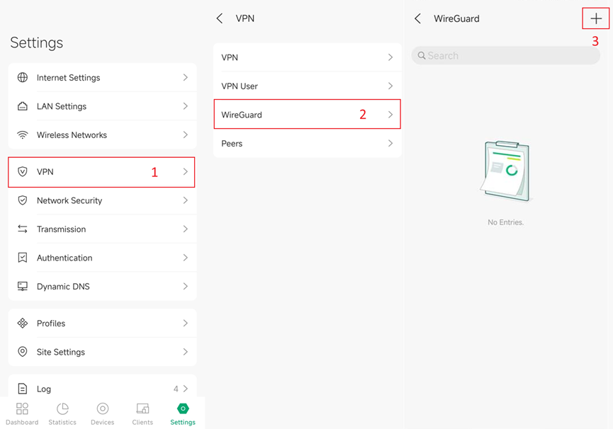
1. In site Settings > VPN > WireGuard, click “+” to create a WireGuard Interface, or editing existing entries.
2. Configure parameters accordingly.
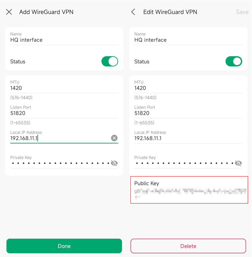
- Name: Specify the name that identifies the WireGuard interface. (This does not affect the VPN tunnel or behavior.)
- Status: Specify whether to enable the WireGuard interface. (Enable or disable your VPN tunnel.)
- MTU: Specify the MTU value of the WireGuard interface. The default value of 1420 is recommended. (Usually, it does not need to be set; it is generally determined automatically by the system.)
- Listen Port: Specify the port number that the WireGuard interface listens to. The default value is 51820. (Usually, the client does not need this to be configured. In this example, our router is the server. You can change this if you need it, and you know what you are doing.)
- Local IP Address: Specify the IP address of the WireGuard interface. (Define the IP address of the WireGuard interface, which should be a non-occupied IP address. It is okay to configure outside your existing LAN range.)
- Private Key: Specify the private key of the WireGuard interface. The value will be automatically generated on the device, and you can also modify it manually (Defines the private key of this specific VPN tunnel. It has to be set and cannot be shared with other tunnels.)
- Public Key: Automatically generated after clicking “Done” to create the Interface.
3. Click “Done” to create the interface.
4. In a created Interface entry, you could click the Public Key to copy it. The Key is needed in step 3 where we would configure peer HQ information in the remote site STA.
Note: Please make sure any IP range configured in VPN local IP address doesn’t overlap with IP range in other sites, to avoid routing issues.
Step 2. Configure the Site STA WireGuard Interface:
Go to Site STA to configure its WireGuard Interface similarly.
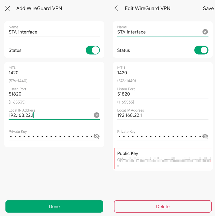
- Name: Specify the name that identifies the WireGuard interface. (This does not affect the VPN tunnel or behavior.)
- Status: Specify whether to enable the WireGuard interface. (Enable or disable your VPN tunnel.)
- MTU: Specify the MTU value of the WireGuard interface. The default value of 1420 is recommended. (Usually, it does not need to be set, and is generally determined automatically by the system.)
- Listen Port: Specify the port number that the WireGuard interface listens to. The default value is 51820. (Usually, the client does not need this to be configured. In this example, our router is the server. You can change this if you need it, and you know what you are doing.)
- Local IP Address: Specify the IP address of the WireGuard interface. (Define the IP address of the WireGuard interface, which should be a non-occupied IP address. It is okay to configure outside your existing LAN range.)
- Private Key: Specify the private key of the WireGuard interface. The value will be automatically generated on the device, and you can also modify it manually (Defines the private key of this specific VPN tunnel. It has to be set and cannot be shared with other tunnels.)
- Public Key: Automatically generated after clicking “Done” to create the Interface.
In a created Interface entry, you could click the Public Key to copy it. The Key is needed in step 4 where we would configure peer STA information in site HQ.
Note: Please make sure any IP range configured in VPN local IP address doesn’t overlap with IP range in other sites, to avoid routing issues.
Step 3. Configure Peer HQ Information in Site STA:
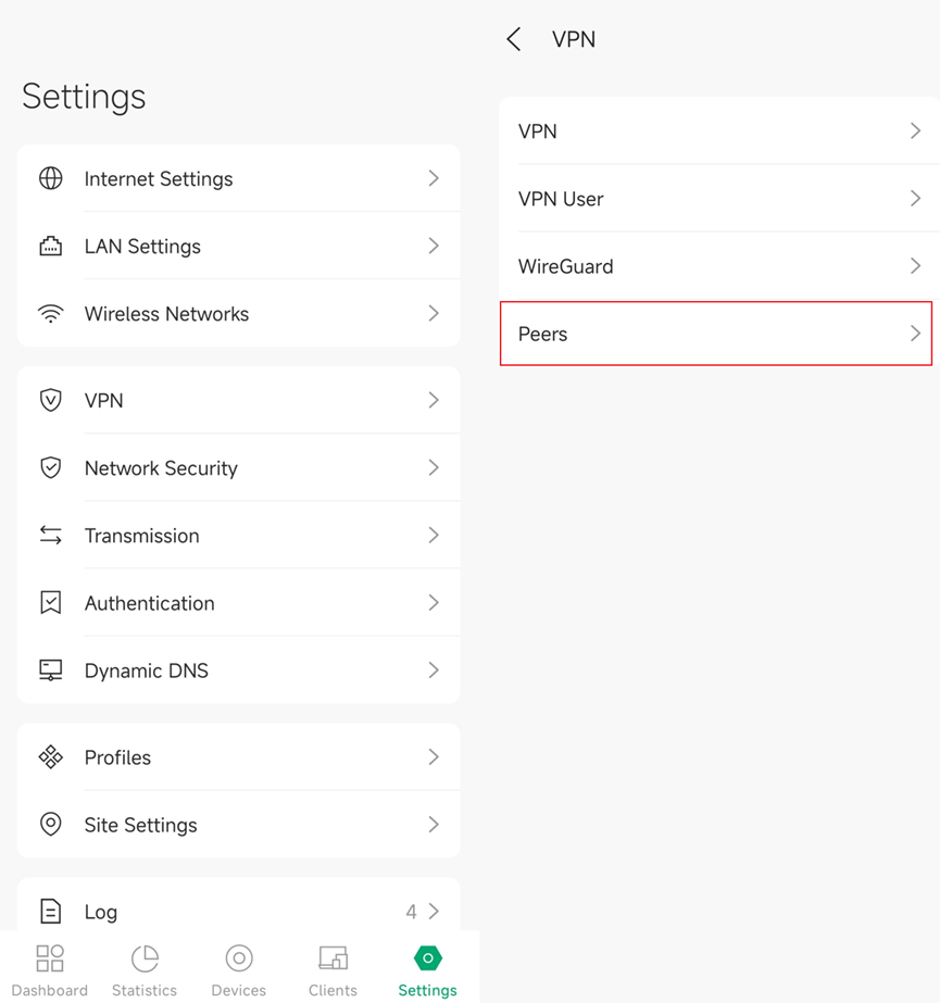
1. In site Settings > VPN > Peers, click “+” to create a WireGuard peer, or edit existing entries.
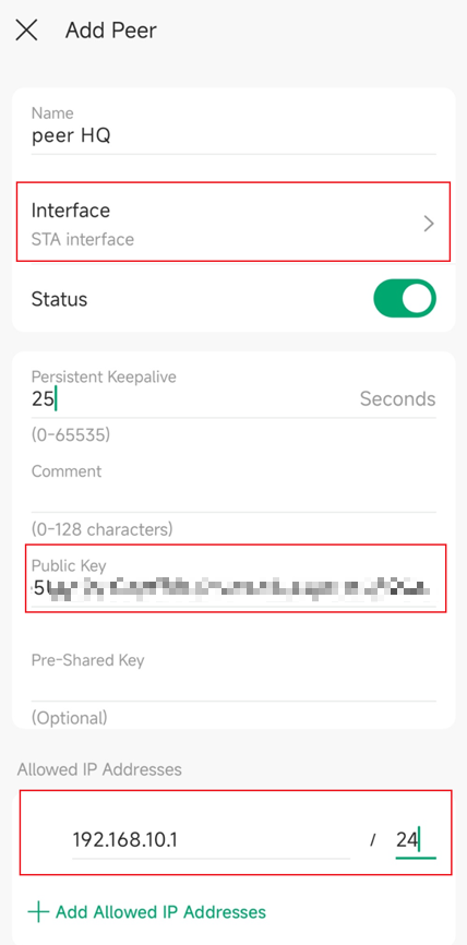
- Name: Specify the name that identifies the WireGuard tunnel.
- Interface: Choose the WireGuard interface to which the peer belongs.
- Status: Specify whether to enable the peer setting.
- Persistent Keepalive: Specify the tunnel keepalive packet interval. (This defines the interval of the keepalive packet sent to the Allowed Address.)
- Comment: Enter the description of the peer.
- Public Key: Fill in the public key of the peer HQ site.
- Pre-Shared Key: Specify a shared key if needed.
- Allowed Address: Specify the address segment that allows traffic to pass through. (Here you should specify the subnet of the peer LAN. This defines what you are allowed to access on the peer site. If you do not include the subnet, then you don't have access to it.)
Step 4. Configure Peer STA Information in HQ site:
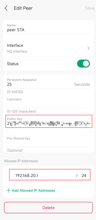
- Name: Specify the name that identifies the WireGuard tunnel.
- Interface: Choose the WireGuard interface to which the peer belongs.
- Status: Specify whether to enable the peer setting.
- Persistent Keepalive: Specify the tunnel keepalive packet interval. (This defines the interval of the keepalive packet sent to the Allowed Address.)
- Comment: Enter the description of the peer.
- Public Key: Fill in the public key of the peer STA site.
- Pre-Shared Key: Specify a shared key if needed.
- Allowed Address: Specify the address segment that allows traffic to pass through. (Here you should specify the subnet of the peer LAN. This defines what you are allowed to access on the peer site. If you do not include the subnet, then you don't have access to it.)
Verification
Use a computer in a Site with allowed IP address to ping another device in the remote site with allowed IP address.
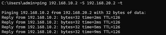
Conclusion
After the configuration is complete, traffic between the allowed IPs on both sides will be securely routed through the WireGuard VPN.
Get to know more details of each function and configuration please go to Download Center to download the manual of your product.
