How to manage EAPs in different subnets using Omada controller (via EAP Discovery Utility) (New UI)
Note: If the management pages of your switch and router are different from this FAQ, refer to How to manage EAPs in different subnets using EAP/Omada controller (via EAP Discover Utility)? (Old UI).
EAP Discovery Utility is a useful assistant for the Omada controller to manage EAPs in different subnets. Take the following topology as an example. Three VLANs (VLAN1, VLAN2, and VLAN3) divide the network into 3 subnets (192.168.0.0/24, 192.168.1.0/24, 172.30.30.0/24). The controller in VLAN1 cannot discover the EAP in VLAN2 by itself because they cannot communicate with each other.
Figure 1 Network Topology

Demonstrated with T2600G-28TS as the switch and TL-ER6120 as the router, this article introduces how to help the controller discover the EAPs in different subnets using EAP Discovery Utility.
Note: DHCP Option 138 can achieve the same effect. For detailed configurations, refer to How to manage EAPs in different subnets using Omada Controller (via DHCP option 138)? (Old UI).
Follow the steps below to configure the switch, the router and the PC running EAP Discovery Utility.
On the switch, create the VLANs and Layer 3 interfaces to set the subnets. Enable DHCP Server and add DHCP Server pools to configure IP addresses and other network parameters that devices obtain from the switch. Add a static routing entry that leads to the gateway router.
1. Go to L2 FEATURES > VLAN > 802.1Q VLAN > VLAN Config. Add port 1/0/4–5 to VLAN2 and add port 1/0/7 to VLAN3 as untagged ports. Remove these ports from the default System-VLAN, so the EAP and PC running the utility can be in the different VLAN with the controller host.
Figure 2 Overview of VLAN Configurations

Figure 3 Configuring VLAN2

Figure 4 Configuring VLAN3

2. Go to L2 FEATURES > VLAN > 802.1Q VLAN > Port Config. Select port 1/0/4 and 1/0/5 and set the PVID as 2. Select port 1/0/7 and set its PVID as 3. Keep other parameters as the default settings. Click Apply.
Figure 5 Configuring VLAN Parameters on Ports

3. Go to L3 FEATURES > Interface. Enable IPv4 Routing and configure Interface entries for each VLAN as shown in Figure 7 and Figure 8.
Figure 6 Overview of Interface Configuration

Figure 7 Configuring Interface for VLAN2

Figure 8 Configuring Interface for VLAN3

4. Go to L3 FEATURES > DHCP Service > DHCP Server > DHCP Server and enable DHCP Server. Click Apply.
Figure 9 Configuring DHCP Server

5. Go to L3 FEATURES > DHCP Service > DHCP Server > Port Settings and click Add to create an IP address pool, respectively, for VLAN1 and VLAN2. Fill in the required field, Default Gateway, and DNS Server. Click Create.
Figure 10 Configuring DHCP Server Pool for VLAN1

Figure 11 Configuring DHCP Server Pool for VLAN2

6. Go to L3 FEATURES > Static Routing > IPv4 Static Routing and add the static default routing entry that leads to the gateway router.
Figure 12 Configuring IPv4 Static Routing

7. Click Save on the top right corner to save all the configuration.
1. Go to Network > LAN to configure the IP address of LAN as 172.30.30.1/24. After configuration, the web browser will be redirected to the new management page automatically.
Figure 13 Configuring LAN

2. Go to Transmission > NAT > Multi-Nets NAT to add Multi-Nets NAT entries for 192.168.0.0/24 and 192.168.1.0/24, so the devices in VLAN1 and VLAN2 can access the internet via the gateway router.
Figure 14 Configuring Muti-Nets NAT for VLAN1

Figure 15 Configuring Muti-Nets NAT for VLAN2

3. Go to Transmission > Routing > Static Route and add static routing entries for VLAN1 and VLAN2, so the router will forward packets with the destination IP address in VLAN1 and VLAN2 to the switch.
Figure 16 Configuring Static Route for VLAN1

Figure 17 Configuring Static Route for VLAN2

For another configuration example of Multi-Nets NAT on TP-LINK SMB router, refer to How to build up a multi-nets network using the Multi-nets NAT feature on TP-Link router with a L3 switch?
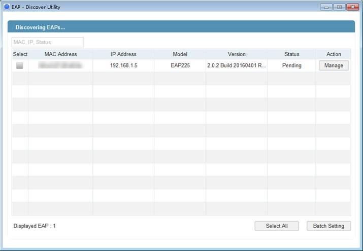
1. Connect the computer running EAP Discovery Utility to switch’s port 1/0/5, and connect EAP to switch’s port 1/0/4, so that EAP Discovery Utility and the EAP are in the same subnet (192.168.1.0/24). Open EAP Discovery Utility and wait for it to discover the EAP.
Figure 18 EAP Discovery Utility discovers the EAP

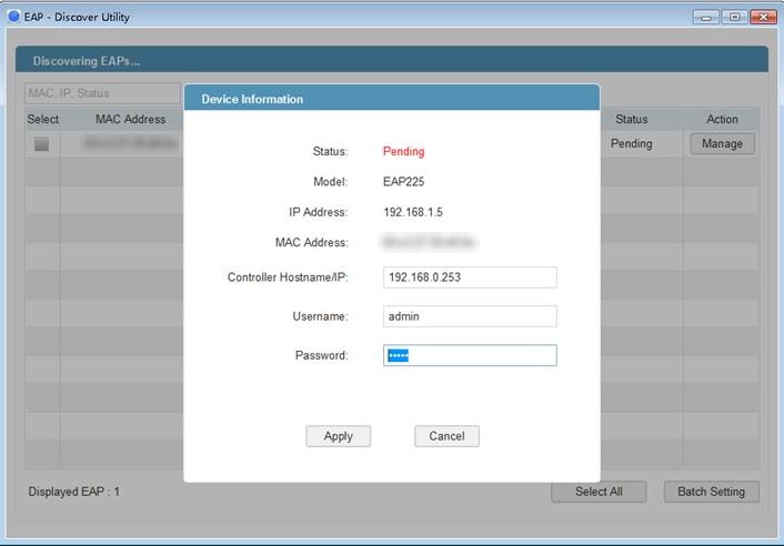
2. After EAP Discovery Utility finds the EAP, click Manage, and then fill in the IP address of the controller host and the username and password of the EAP (both are admin by default) to help the Omada controller find this EAP. Click Apply.
Figure 19 Configuring the Device Information

Note: After the controller successfully adopts the EAP, you can remove the computer running EAP Discovery Utility from the network.
Now you can launch the Omada Controller and manage the EAP. The EAP which has been configured by EAP Discovery Utility just now will appear in the Pending list.
Figure 20 Configuring the Device Information

If the controller still cannot discover the EAP, refer to What should I do when the controller fails to discover the EAP? to find the problem and solve it.
Get to know more details of each function and configuration please go to Download Center to download the manual of your product.


