


Giới thiệu
ERPSv2 (Ethernet Ring Protection Switching) là giao thức bảo vệ mạng vòng Layer 2, giúp ngăn chặn vòng lặp mạng và cung cấp khả năng khôi phục nhanh trong các mạng Ethernet dạng vòng. Bằng cách chặn một Ring Protection Link (RPL) được chỉ định trong điều kiện hoạt động bình thường và tự động khôi phục đường truyền lưu lượng khi xảy ra sự cố liên kết, ERPSv2 giúp duy trì khả năng dự phòng của mạng và tính liên tục của dịch vụ. Hướng dẫn này trình bày cách cấu hình ERPSv2 trên các Switch dòng công nghiệp Omada, bao gồm triển khai Major Ring và Sub-Ring, nhằm xây dựng mạng Ethernet công nghiệp không xảy ra vòng lặp và có tính sẵn sàng cao.
Yêu cầu
- Omada Industrial Switch (Firmware phiên bản 6.3.0 trở lên)
Cấu hình
Trong mạng ERPS, mỗi Switch tham gia vào mạng vòng được gọi là một node. Nhóm các Switch được kết nối với nhau và sử dụng cùng một Control VLAN sẽ tạo thành một ERPS Ring. Control VLAN chỉ được sử dụng để truyền các gói tin giao thức ERPS và không nên được sử dụng cho lưu lượng người dùng thông thường. Các VLAN mang lưu lượng người dùng được bảo vệ bởi Protection Instance, xác định những VLAN nào sẽ được ERPS kiểm soát trong quá trình chuyển tiếp thông thường và khi thực hiện chuyển mạch bảo vệ. Thiết kế này cho phép giao thức ERPS quyết định thời điểm lưu lượng được chuyển tiếp hoặc bị chặn, giúp tránh vòng lặp mạng và gián đoạn dịch vụ.
Mô hình triển khai
Mỗi ERPS Ring sử dụng các vai trò cổng khác nhau để kiểm soát việc chuyển tiếp lưu lượng. Cổng RPL Owner là cổng chính chịu trách nhiệm chặn RPL trong điều kiện hoạt động bình thường và mỗi ERPS Ring chỉ có một RPL Owner. Cổng RPL Neighbor được kết nối trực tiếp với cổng RPL Owner và được hỗ trợ trong ERPSv2.
Các cổng còn lại trong Ring là Normal ports, có nhiệm vụ giám sát các liên kết ERPS được kết nối trực tiếp và báo cáo các thay đổi về topology. Các cổng trong ERPS Ring có thể ở một trong hai trạng thái: Forwarding, trong đó cổng chuyển tiếp cả lưu lượng người dùng và các gói tin ERPS; hoặc Discarding, trong đó cổng chỉ gửi và nhận các gói tin ERPS.
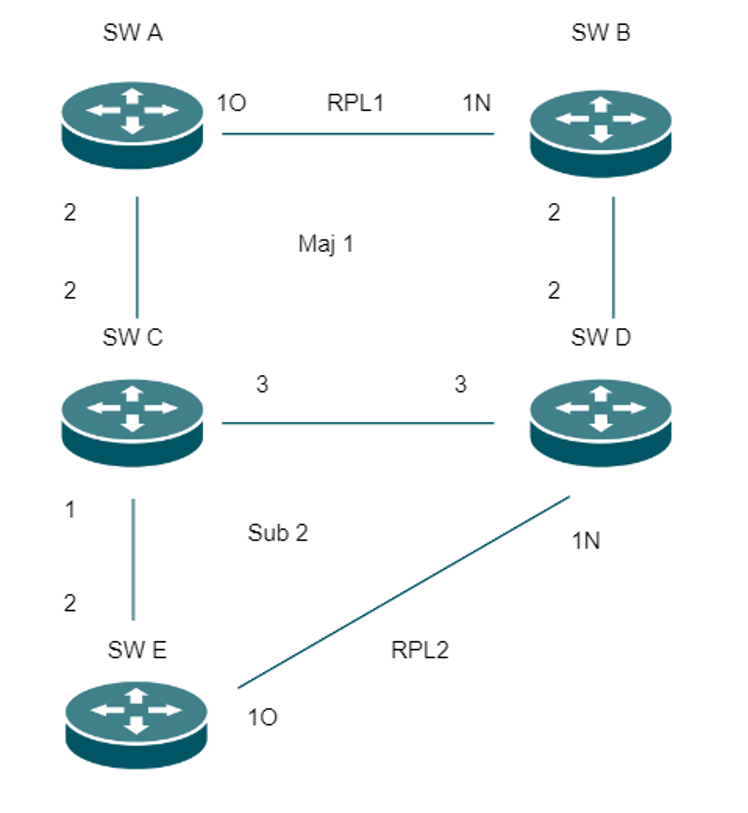
Topology dưới đây minh họa một mô hình triển khai ERPSv2 điển hình gồm một Major Ring (maj1) và một Sub-Ring (sub2). Các Switch A, B, C và D tạo thành Major Ring, trong khi các Switch C, D và E tạo thành Sub-Ring. Hai Ring được kết nối với nhau thông qua Switch C và D, đóng vai trò là các interconnection node giữa Major Ring và Sub-Ring.
Hai Ring Protection Link (RPL) được xác định trong topology này:
- RPL1 được thiết lập giữa Switch A và Switch B, trong đó Switch A được cấu hình làm RPL Owner (1O) và Switch B làm RPL Neighbor (1N).
- RPL2 được thiết lập giữa Switch E và Switch D, trong đó Switch E được cấu hình làm RPL Owner (2O) và Switch D làm RPL Neighbor (2N).
Tất cả các cổng Ring còn lại được cấu hình làm Normal ports và tham gia vào quá trình chuyển mạch bảo vệ của ERPS.
Lưu ý:
- Hiện tại, cấu hình ERPS trên các Switch dòng công nghiệp Omada chỉ được hỗ trợ trong Standalone Mode.
- Tính khả dụng của tính năng và các tùy chọn cấu hình có thể khác nhau tùy theo model Switch. Vui lòng tham khảo Web UI để kiểm tra các tham số thực tế được thiết bị của bạn hỗ trợ.
- Hiện tại, các Switch dòng công nghiệp Omada chỉ hỗ trợ ERPSv2. ERPSv2 hoàn toàn tương thích với ERPSv1 và có thể hoạt động tương tác với các thiết bị ERPSv1 của bên thứ ba. Tuy nhiên, để đạt hiệu suất hội tụ tối ưu và tránh các vấn đề tương thích không mong muốn, khuyến nghị sử dụng các Switch dòng công nghiệp Omada trên toàn bộ mạng ERPS bất cứ khi nào có thể.
- Khi Sub-Ring được cấu hình ở Virtual Channel (VC) Mode, hãy thêm thủ công các interconnection port liên quan trên Major Ring làm thành viên tagged của Sub-Ring Control VLAN để các thông báo thay đổi topology có thể được truyền chính xác.
- Control VLAN được sử dụng bởi một ERPS Ring phải sử dụng VLAN ID chưa được tạo trong 802.1Q VLAN. Cấu hình ERPS chỉ có thể được áp dụng khi một VLAN ID chưa được sử dụng được chọn làm Control VLAN.
- Khuyến nghị dành riêng Control VLAN cho hoạt động ERPS. Hạn chế thêm các cổng không thuộc ERPS vào Control VLAN bất cứ khi nào có thể.
Các tham số cấu hình ERPS
Trong toàn bộ bài viết này, topology được trình bày ở trên sẽ được sử dụng làm ví dụ triển khai. Các phần tiếp theo giải thích cách cấu hình những tham số ERPS chính cần thiết cho cơ chế bảo vệ Ring, bao gồm Ring ID, Control VLAN, Protection Instance, Ring Type (Major Ring hoặc Sub-Ring), Member Ports, Port Roles (RPL Owner, RPL Neighbor và Normal), ERPS Version và các Protection Timer. Các tham số này xác định topology của ERPS Ring và quyết định cách mạng phát hiện sự cố cũng như thực hiện chuyển mạch bảo vệ.
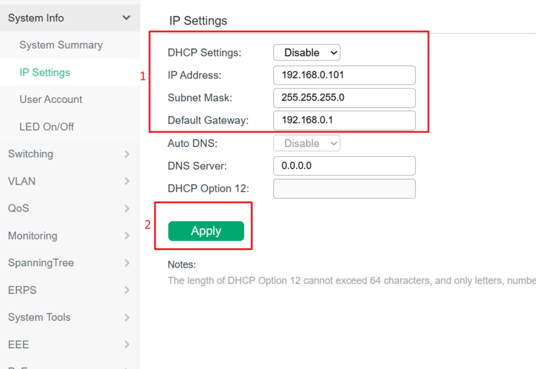
Bảng dưới đây tóm tắt các thiết lập ERPS được sử dụng trong ví dụ triển khai này. Trước khi cấu hình ERPS, hãy kết nối từng Switch với mạng quản lý và đảm bảo có thể truy cập Switch thông qua Web UI. Bạn có thể để Switch tự động nhận địa chỉ IP thông qua DHCP hoặc gán địa chỉ IP tĩnh theo yêu cầu của mạng. Trong ví dụ này, địa chỉ IP tĩnh chỉ được sử dụng cho mục đích quản lý và kiểm tra nhằm tránh xung đột địa chỉ trong quá trình cấu hình.
|
Switch |
IP Address |
Ring ID |
Control VLAN |
Ring Type |
Member Port 1 |
Member Port 2 |
MEL |
Virtual Channel |
TC Notify |
|
A |
192.168.0.101 |
1 |
10 |
Major |
Port 1 (RPL Owner) |
Port 2 (Normal) |
6 |
— |
— |
|
B |
192.168.0.102 |
1 |
10 |
Major |
Port 1 (RPL Neighbor) |
Port 2 (Normal) |
6 |
— |
— |
|
C |
192.168.0.103 |
1 |
10 |
Major |
Port 2 (Normal) |
Port 3 (Normal) |
6 |
— |
— |
|
C |
192.168.0.103 |
2 |
20 |
Sub |
Port 1 (Normal) |
— |
7 |
Disable |
Ring 1 |
|
D |
192.168.0.104 |
1 |
10 |
Major |
Port 2 (Normal) |
Port 3 (Normal) |
6 |
— |
— |
|
D |
192.168.0.104 |
2 |
20 |
Sub |
Port 1 (RPL Neighbor) |
— |
7 |
Disable |
Ring 1 |
|
E |
192.168.0.105 |
2 |
20 |
Sub |
Port 1 (RPL Owner) |
Port 2 (Normal) |
7 |
Disable |
— |
Các tham số sau đây được cấu hình giống nhau trên tất cả các Switch, trừ khi có chỉ định khác:
Protection Instance: 1
WTR Timer: 5
Guard Timer: 200
Hold-off Timer: 0
Revertive Mode: Enable
Quy trình cấu hình
Bước 1 (Tùy chọn). Truy cập giao diện Web của Switch
Kết nối từng Switch với mạng quản lý và truy cập giao diện quản lý Web của Switch trong Standalone Mode. Có thể truy cập Switch bằng địa chỉ IP được cấp tự động qua DHCP hoặc địa chỉ IP quản lý được cấu hình thủ công. Đảm bảo bạn có thể đăng nhập thành công vào Web UI trước khi tiến hành cấu hình ERPS.
Bước 2. Bật 802.1Q VLAN
Đi tới VLAN > 802.1Q VLAN và bật chức năng 802.1Q VLAN trên tất cả các Switch.

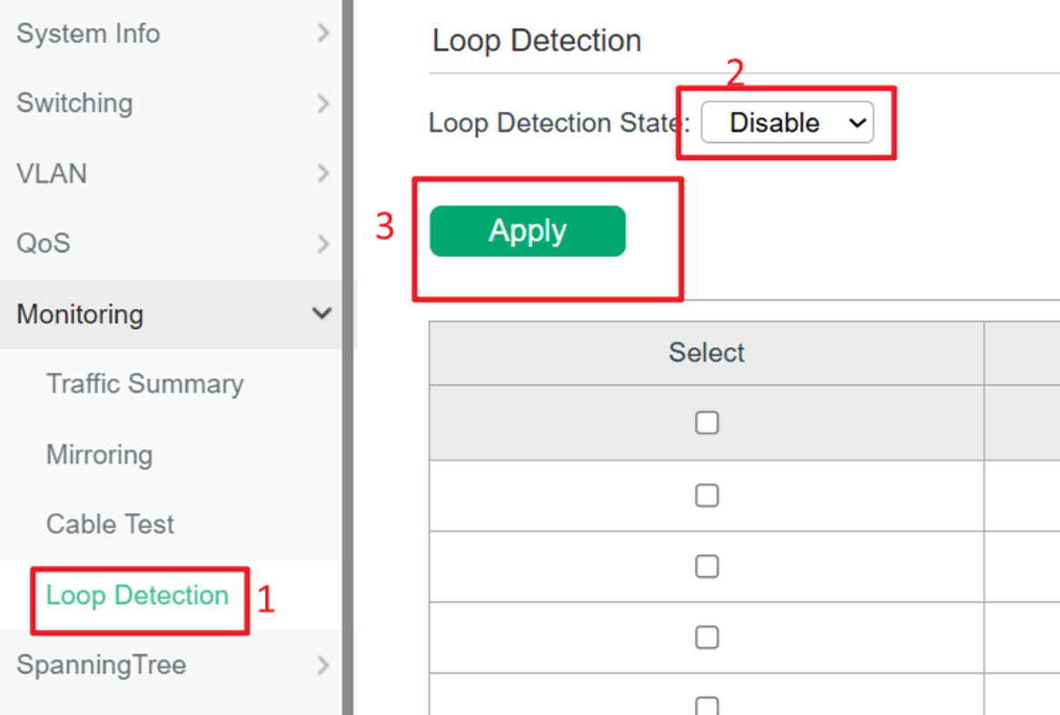
Bước 3. Tắt STP và kiểm tra trạng thái Loop Detection
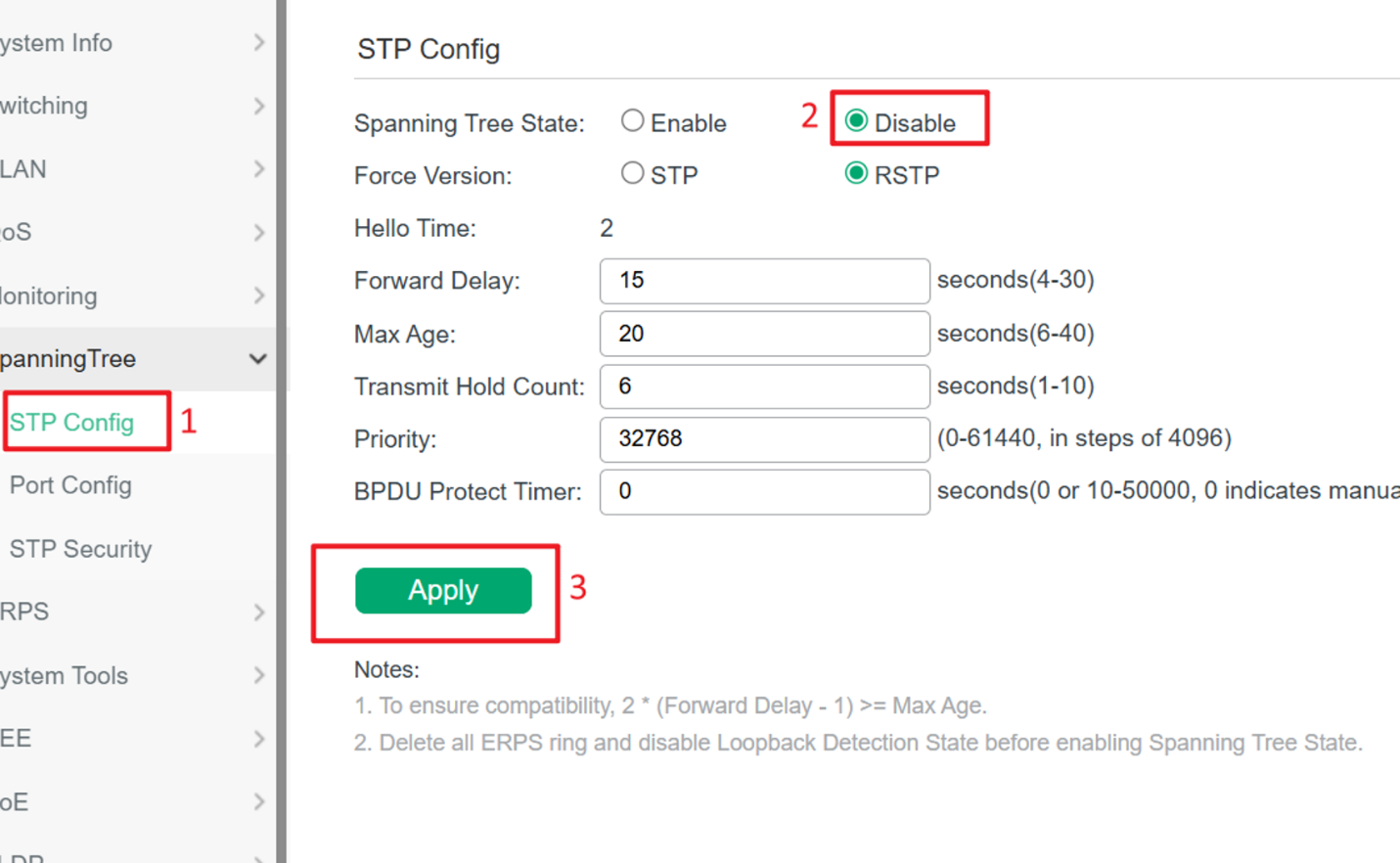
Đi tới Spanning Tree > STP Config trên từng Switch. Tắt STP trước khi cấu hình ERPS để tránh xung đột với cơ chế bảo vệ Ring.
Bước 4. Tạo ERPS Instance cho Major Ring
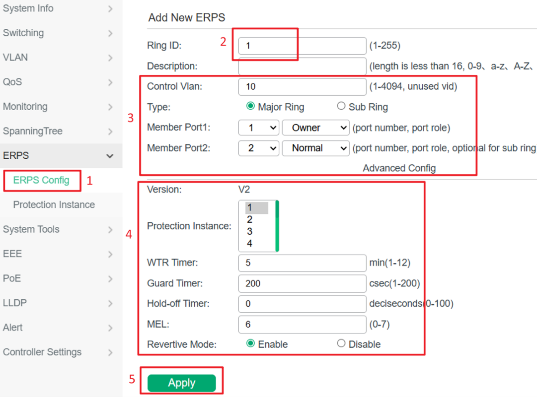
Đi tới ERPS > ERPS Config. Trang ERPS hiển thị các Ring đã được cấu hình và trạng thái hoạt động hiện tại của chúng.
Trong mục Add New ERPS, tạo một ERPS Ring mới. Lấy cấu hình Major Ring trên Switch A làm ví dụ, cấu hình các tham số như sau: Ring ID là 1, Control VLAN là 10, Ring Type là Major Ring, Member Port 1 là RPL Owner, Member Port 2 là Normal, Protection Instance là 1, WTR Timer là 5, Guard Timer là 200, Hold-off Timer là 0, MEL là 6 và Revertive Mode là Enable. Sau khi hoàn tất cấu hình, nhấp vào Apply để lưu các thiết lập và tạo ERPS Ring.
Bước 5. Cấu hình Sub-Ring (Ví dụ trên Switch C)
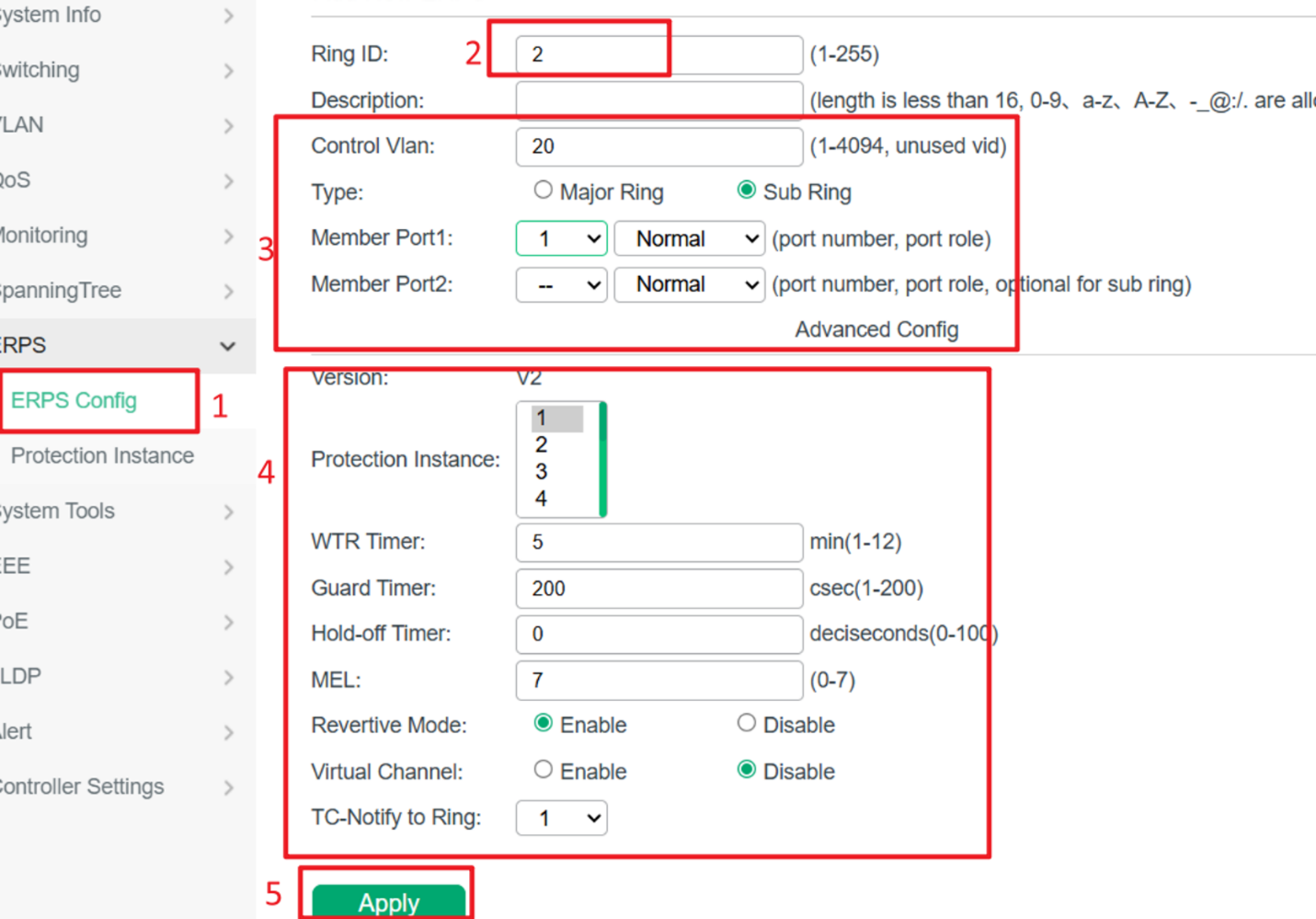
Sau khi hoàn tất cấu hình Major Ring, tiếp tục cấu hình Sub-Ring trên Switch C. Cấu hình các tham số như sau: Ring ID = 2, Control VLAN = 20, Member Port 1 = Normal và Virtual Channel = Enable hoặc Disable tùy theo yêu cầu triển khai. Notify Ring ID phải trùng với Ring ID của Major Ring để các thông báo thay đổi topology có thể được truyền chính xác giữa hai Ring.
Do Switch C là một interconnection node giữa Major Ring và Sub-Ring, chỉ cần cấu hình một Member Port cho Sub-Ring Instance. Cổng này được sử dụng để kết nối với Sub-Ring và tham gia vào quá trình chuyển mạch bảo vệ ERPS.
Bước 6. Xác minh cấu hình Protection Instance
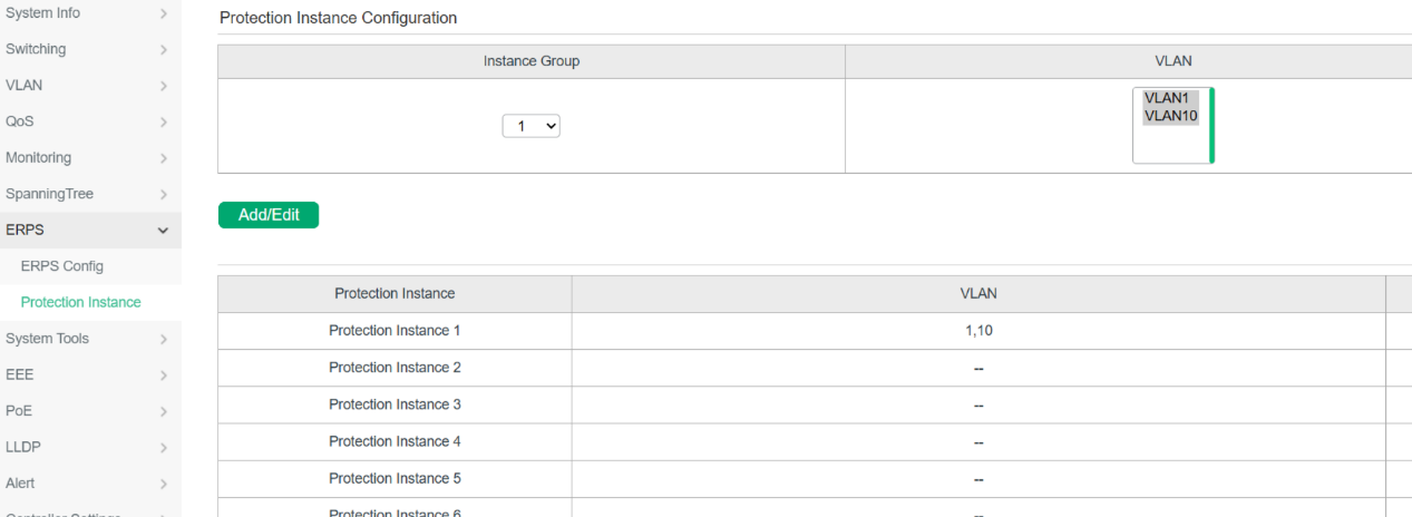
Protection Instance đã tạo sẽ được hiển thị trong bảng Protection Instance như hình bên dưới, cho phép bạn xác minh rằng việc ánh xạ VLAN-to-Instance đã được cấu hình thành công.
Bước 7. Cấu hình các Switch còn lại
Lặp lại các bước cấu hình ở trên cho các Switch còn lại theo bảng Configuration Parameters. Sau khi hoàn tất cấu hình trên tất cả các Switch, kết nối các Switch theo topology được minh họa. Khi tất cả các liên kết đã được thiết lập, tiến hành kiểm tra trạng thái của ERPS Ring.
Bước 8. Xác minh trạng thái ERPS Ring
Sau khi tất cả các liên kết đã được thiết lập, đi tới ERPS và kiểm tra trạng thái Ring trên từng Switch. Khi cấu hình thành công và ERPS Ring đã hội tụ, State của ERPS Instance tương ứng sẽ chuyển sang Idle, cho biết Ring đang hoạt động bình thường và cơ chế bảo vệ ERPS đang hoạt động.

Bước 9. Thực hiện các thao tác Protection Switching (Tùy chọn)
Sau khi ERPS Ring hoạt động bình thường và State hiển thị là Idle, người dùng có thể thực hiện các thao tác Protection Switching ở phía trên trang ERPS. Các thao tác được hỗ trợ bao gồm Force Switch (FS), Manual Switch (MS) và Clear. Các chức năng này chủ yếu được sử dụng cho mục đích bảo trì, khắc phục sự cố, kiểm tra failover hoặc thay đổi thủ công đường chuyển tiếp lưu lượng.
- Force Switch (FS): Chặn ngay lập tức cổng được chọn, bất kể trạng thái hiện tại của Ring.
- Manual Switch (MS): Thay đổi thủ công điểm chặn khi Ring đang ở trạng thái Idle hoặc Pending.
- Clear: Xóa thao tác FS hoặc MS hiện có và khôi phục hoạt động ERPS bình thường.

Kết luận
Bài viết này hướng dẫn cách cấu hình một topology ERPSv2 điển hình gồm Major Ring và Sub-Ring trên các Switch dòng công nghiệp Omada, bao gồm tạo Protection Instance, cấu hình ERPS Ring, gán vai trò cho các cổng và xác minh trạng thái hoạt động.
Sau khi hoàn tất cấu hình và tất cả các Switch được kết nối theo đúng topology, trong điều kiện hoạt động bình thường, ERPS Instance sẽ chuyển sang trạng thái Idle. Trong khi đó, trạng thái Protection cho biết ERPS đã phát hiện sự cố liên kết và thực hiện chuyển mạch bảo vệ nhằm duy trì tính sẵn sàng của dịch vụ.
